Desktop IE11 Helps Debug Windows Phone 8.1 Browser but Also Going Away Soon

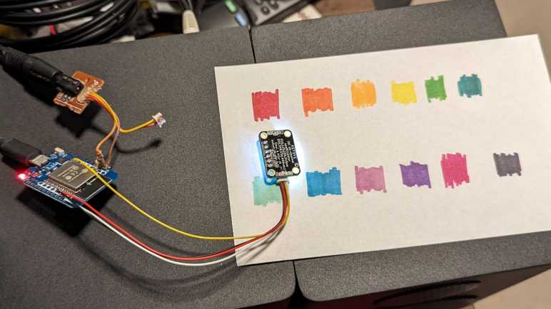
I’m playing with the AS7341 spectral color sensor and decided to use it as an exercise in browser app development. I’ve learned a lot as I went. Serving the HTML file from my ESP32 was more annoying than I think it ought to be under Arduino IDE, certainly more complex than creating the HTTP API endpoint to begin with, but I’m setting that aside for now. I wanted to revisit another idea: browser apps on Windows Phone 8.1. Since Microsoft has long since shut down the app development platform for Windows Phone, its browser is the only remaining entry point to utilize those old phones rather than dump them in electronics recycle.

I booted up my old Lumia 920 (a decade old at this point) and pointed it at my ESP32. I saw my static HTML input controls render on screen, but none of the interactive features worked. Something is wrong with my JavaScript, but what? I ran into this challenge earlier, trying to get ESP32 Micro Sawppy control working on the same Lumia 920. Debugging the issue was an exercise in frustration because Microsoft had removed all development resources including debugger support. Which meant I was staring at a blank screen with no error message to point me in the right direction. Just tedious trial and error. I knew I must find a better way.

Since then, I had an idea I wanted to try: according to Wikipedia, the Windows Phone 8 browser was built out of Internet Explorer 11 code base. And I still have IE11 on my Windows 10 machines. I had hoped it would give me error messages to guide my debugging, and it did! IE11 Developer Tools console gave me an error message complaining about a backtick as an invalid character. This was because IE11 did not support template literals, and now with an error message I knew to switch to a different way to manipulate strings. The next “invalid character” error was for “=>” and that was because IE11 didn’t do arrow function expressions, again easily addressed.

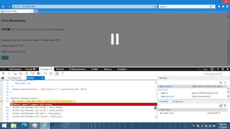
Then I ran into “Object doesn’t support this action” error pointing at the URL class constructor. Double-checking caniuse.com confirmed IE11 lacked URL class. This would take more effort to address, so I aborted my IE11-friendliness experiment at this point. Before my web app would work on IE11 (and hopefully Windows Phone 8.1 browser) I would have to convert the URL class. I probably also have to switch my input control event listeners from “input” event (which never fired under IE11) to “change“.

But even as I found this solution to debug under IE11, the solution may soon be taken away from me. IE11 reached end of life on 2022/6/15. In a few weeks (2023/2/14 as of this writing) Microsoft plan to forcibly remove IE11 from Windows machines. The official alternative is running Microsoft’s Edge browser to run in Internet Explore mode, but its own developer tools are not available while running in that mode. I have to kick off something called “IEChooser” (%systemroot%\system32\f12\IEChooser.exe) in order to get a debugger experience, and only a partial one at that.

I knew Windows Phone 8.1 itself has long gone off into the sunset, and soon IE11 will follow. Web platforms have been dropping IE11 support for years. For example, Angular stopped supporting IE11 in November 2021 with their version 13. If I am to make use of my old Windows Phone 8.1 devices via a browser app, I could use desktop IE11 to help me debug compatibility issues for now, but probably not for long. With all of its limitations, it might as well be an entirely different platform.


Code changes for this experiment is publicly visible on GitHub

ESP32 Arduino Web Server: No File Upload?

In the interest of data integrity and security, modern web browsers impose constraints on JavaScript code running within that browser’s environment. I ran into two of them very early on: CORS and Mixed Content. They restrict how content from different web servers are allowed to interact with each other, which was a situation I stumbled into by hosting a HTTP endpoint on my ESP32 and hosting my browser UI files on my desktop computer: these are different servers!

The easiest way to avoid tripping over constraints like CORS or Mixed Content is to serve everything from the same server. In my case, that meant I should serve my browser UI HTML/JavaScript alongside AS7341 HTTP endpoint on the same ESP32. Sadly, this isn’t as easy as I had hoped because Arduino doesn’t really have the concept of uploading files to a board. When we choose “Upload Sketch” it will compile and upload executable code, but there’s no way to also send my index.html and script.js files for serving over HTTP. Probably because such support varies wildly across different Arduino-compatible microcontrollers.

For ESP32 specifically, a section of flash memory can be allocated for use like a disk drive via a mechanism called SPIFFS. It is possible to put HTML and JavaScript files in SPIFFS to be served via HTTP. (Example: ESPAsyncWebServer can serve files from SPIFFS.) I implemented this concept for an ESP32-based Micro Sawppy controller, but that was using Espressif’s ESP-IDF framework inside the PlatformIO environment. There’s no direct counterpart for Arduino framework and Arduino IDE. Somebody has written an Arduino IDE extension to upload files to ESP32 SPIFFS, but that was last released in 2019 and as of writing is not yet compatible with latest version of Arduino IDE.

I could embed those files as strings directly in source code, but that means I have to review my HTML and JavaScript to make sure I’m not using any special characters. The most obvious requirement is exclusive use of single quotes and no double quotes. Any backslash would also have special meaning in Arduino source code. This can get annoying very quickly.

An alternative is to treat those files as binary files and embed them in source code as hexadecimal values. I’ve done this for embedding animated GIF data inside an Arduino sketch, and there’s a handy command to do so: “xxd -i index.html index.html.h” This uses xxd, a hex dump command-line utility included in Ubuntu distributions by default. I still have to modify the output file, though:

  1. Add “const” keyword to make sure it goes into flash storage instead of RAM.
  2. Remove “unsigned” keyword to fit with signature for WebServer server.send().
  3. Add a 0x00 to the end of the hex dump to null-terminate the string. (Technically it means I should add 1 to the “length” value as well, but I’m not using that value.)

This works, but still quite cumbersome. I’m not sure it’s better than the hassle of writing HTML and JavaScript in a C string compatible way. There has to be something better than either of these options, but until I find it, I’ll jump through these hoops. Fortunately, I only have to do this when updating files served by my ESP32. Most of the time I’m updating code and seeing how they work served from my development desktop, a much simpler process that made debugging challenges less of a headache than they already are.


Code for this project is publicly available on GitHub

HTML Location Matters for CORS and Mixed Content

I have written a basic browser-based UI to interact with an AS7341 spectral color sensor. I wanted an educational learning project and that’s exactly what I got. My first lesson happened before I could even get anything onscreen! I had my ESP32 translating a formatted HTTP GET request into a call into Arduino AS7341 library readAllChannels() and return the results as JSON. This basic browser-based UI was supposed to query that ESP32 and display results onscreen. In the interest of rapid development, I hosted the browser HTML and JavaScript files on my desktop, and that was my mistake. The HTTP GET action failed with this error message in the browser developer console:

Access to fetch at 'http://esp32-as7341.local/as7341?atime=29&astep=599&gain=8&led_ma=0' from origin 'http://localhost:8080' has been blocked by CORS policy: No 'Access-Control-Allow-Origin' header is present on the requested resource. If an opaque response serves your needs, set the request's mode to 'no-cors' to fetch the resource with CORS disabled.

As a beginner web developer, I had no idea what this error message meant. My journey of enlightenment started by searching for this error message, which led me to this page that unfortunately assumed more knowledge than I had. But this error message did suggest a solution of setting ‘no-cors’ which I tried without understanding what it meant. I no longer got the error message, but I didn’t get any data results, either. I read up on “What is an opaque response?” and confirmed data results were intended to be inaccessible. Well, that’s not going to work for me! So I went to MDN page on CORS. “Cross-Origin Resource Sharing” is something a web server has to explicitly choose to participate in, something my ESP32 Arduino sketch has not done. I decided it’s OK for arbitrary web pages to query my ESP32 and I could declare that with a single additional line added to my Arduino sketch (wildcard for Access-Control-Allow-Origin).

server.sendHeader("Access-Control-Allow-Origin", "*");

Once my ESP32 started sending that in its server headers, I could host browser HTML and JS from my desktop development server and enjoy the rapid code/test/fix/repeat loop of browser JavaScript code. But what about later? It would be a big hassle to require everyone to set up their own web server to play with this code. I thought I had a solution for that: host the browser UI on GitHub pages, but that idea was also a failure. When I tested the idea, I got this error:

Mixed Content: The page at 'https://roger-random.github.io/as7341_webui/' was loaded over HTTPS, but requested an insecure resource 'http://esp32-as7341.local/as7341?atime=29&astep=599&gain=8&led_ma=0'. This request has been blocked; the content must be served over HTTPS.

So much for that! I remember early days of the web when it was common to mix HTTP and HTTPS. My banking site was in HTTPS but used icons and images served over HTTP. This approach meant the server didn’t have to encrypt those images, saving CPU time and its follow-on effects. (Lower electricity consumption, less datacenter cooling, etc.) But it didn’t take long before nefarious geniuses figured out how to cause problems, so mixing HTTP and HTTPS went from commonplace, to triggering a notification, to triggering obnoxious dialogs, and now to complete ban. GitHub Pages would not serve over HTTP, and I’m not going to make everyone jump though the hoops of adding HTTPS to an ESP32 Arduino sketch.

To avoid problems with CORS and with Mixed Content, the best solution is to have my ESP32 Arduino sketch serve the HTML and JavaScript in addition to the AS7341 HTTP API endpoint. This turned out to be more complicated than I thought it would be.


Code for this project is publicly available on GitHub

Basic Browser UI for AS7341

I wrote an ESP32 Arduino sketch that exposes Adafruit AS7341 library readAllChannels() to be accessible via HTTP GET. Now I need to write browser-side code to use it. My first version will be bare bones: plain HTML and as little JavaScript as I can get away with. No consideration will be given for page layout aesthetics, so no CSS will be involved.

Input controls are direct translation of AS7341 parameters: atime, astep, and gain. Output will be JSON returned by my ESP32 sketch, direct with no processing. Making the AS7341 parameters more user-friendly is out of scope for this first version, as is any of the processing and visualization of AS7341 data. I want to do both in the future, but not at first. I wanted to start with this level of direct input/output because I intend to keep this first version around for debugging purposes: when my future fancy version goes awry, I want to be able to bring up this basic version to verify the sensor itself and the network API is still working correctly.

But I deviated from that bare-bones intent pretty quickly, because as soon as I started moving those setting sliders around, I wanted more. I added some JavaScript code to calculate the integration time (in milliseconds) described by atime and astep parameters, and I also added a slider to control milliamps of current to illuminate onboard LED during measurement. (Zero milliamps to turn LED off.) After a few measurements of LED flashing in my face, I added another parameter: whether or not to leave LED illuminated after taking a measurement. A steady-on LED is less annoying than a rapidly blinking one.

Another reason for keeping the user interface bare-bones is to verify all behind-the-scenes infrastructure are working as I expected. They did not! Debugging those failures led me to realize my ignorance with some security-related web development concepts. This is great: I wanted a learning project, and now I’m learning about “CORS” and “Mixed Content”.


Code for this project is publicly available on GitHub

ESP32 WebServer Made AS7341 Accessible via HTTP GET

I’ve decided to build an interactive AS7341 explorer application using web-based technologies, shifting most of the interactive input and visual output to a web browser. But web-based technologies are not able to communicate directly to an AS7341 via I2C, so I still need something to bridge the hardware to the browser. The answer is a small ESP32 Arduino Core sketch using Adafruit’s AS7341 library on one side and a web server library on the other.

In the interest of starting simple, I used the WebServer library included as part of ESP32 Arduino Core. This is a simple implementation of HTTP server that can only handle a single connection at a time, but its limited features also meant simple code. I started with the HelloServer example which does everything I need: parse arguments and send a response. The most informative section is the handler for “HTTP 404 Not Found”, as this is where it prints out all the arguments parsed out of the URI and serves as a handy reference to do the same in my implementation. I wanted to be able to pass in AS7341 parameters “atime” and “astep” to control sensor exposure time, “gain” for sensitivity, and “led_ma” to control brightness of illumination LED. These parameters are passed directly into Adafruit AS7341 API.

My first iteration would turn on LED just for the duration of sensor integration then turn it off. But when I read the sensor continuously in a loop, this would result in an annoying flash between reads. To address this problem, I added a “led_stay_on” parameter to control whether the illumination LED would stay on between reads.

Once sensor integration is complete, I packaged readings for sensors F1-F8, Clear, and NIR into a JSON formatted string and returned it to caller as mime type application/json.

{
  "415nm" : 7,
  "445nm" : 22,
  "480nm" : 31,
  "515nm" : 65,
  "555nm" : 113,
  "590nm" : 175,
  "630nm" : 243,
  "680nm" : 125,
  "clear" : 408,
  "nir" : 28,
  "settings" : {
    "atime" : 10,
    "astep" : 599,
    "gain" : 64,
    "led_ma" : 0
  }
}

In hindsight, using an ESP32 was overkill: an ESP8266 would have been perfectly capable of serving as a HTTP to I2C bridge. But I already had this ESP32 ready to go, so I stayed with it.

If I want capabilities beyond what that simple WebServer library could do, in the future I could swap it out for something more powerful like the ESPAsyncWebServer library. It includes a templating feature so I wouldn’t have to do as much direct string manipulation. It also includes the ArduinoJson library for simpler and more robust JSON formatting instead of the string operations I used. And finally, it includes WebSocket capability which would be very useful if I want to migrate the messy ESP-IDF code I wrote for my ESP32 Sawppy controller.

But for today, simple WebServer should be enough to let get me started on browser side code.


Code for this project is publicly available on GitHub

New Project: AS7341 Interactive Web UI

I’ve modified my ESP32 development board to help me better understand the AS7341 spectral color sensor. I’ve removed provision for Mozzi audio output, added heat-shrink tubing to reduce damage from handling, and covered a worryingly bright power LED on Adafruit’s AS7341 board. That takes care of the hardware, but what about the software?

Here are my goals:

  • Allow interactive adjustments to AS7341 parameters. Right now, I have to edit parameters in code, compile the Arduino sketch, and upload to my ESP32 before I can see how changes in parameters affect output. I want to streamline this process.
  • Better visualize AS7341 sensor data. Right now, I just receive a list of numbers. While sufficient for some fun experiments like Emily’s color organ, they are not the most intuitive presentation of vision-based data.
  • Rapid experimentation for sensor normalization. Every light source has a different spectrum, and every individual filter on the AS7341 has a different response curve. How do I compensate for those variations in a “good enough” way? AMS has an Application Note on precisely calibrating AS7341 results, but that requires domain specific expertise such as CIE color spaces. I want to be able to play with ideas and hope to find something that’s 80% as good for 10% of the effort.

For an ESP32, adding interactive adjustments should be easy. I can solder in a few potentiometers, and an ESP32 has plenty of ADC channels to let me pipe that through. I also have a lot of options for ESP32 display. My most recent Adafruit order (which included my AS7341 breakout board) included a small 1.8″ color LCD which would work well. Where this idea might fall apart is my wish for rapid experimentation. It only takes about thirty seconds for me to compile an ESP32 Arduino Core sketch and upload it to my ESP32 board, but that time adds up if I’m trying a lot of small changes in rapid succession. Wouldn’t it be nice if I could iterate as quickly as web development? In that world, I can make a small change and hit F5 to refresh my browser and see immediate results.

Then I realized: hey, I could totally do that! In fact, it would line up with my desire to practice working with web related technologies. Using HTML controls, I could quickly add points of interactivity. There would be no shortage of display options to visualize AS7341 data on screen, and I get that rapid edit/F5/result loop I wish for. Would this be the best way to interactively visualize AS7341 data? Probably not! But it’s a way for me to build my hardware and software skills simultaneously, making it a great learning project for my purposes. I will start by writing a thin stub running on my ESP32 to interact with AS7341, then I can get my feet wet with browser-side development.


Code for this project is publicly available on GitHub

Modifying ESP32 Mini to Focus on AS7341

In order to eliminate Mozzi audio glitches while reading AS7341 spectral color sensor, I was prepared to dive down to learn ESP-IDF I2C API. Fortunately, it turned out Adafruit AS7341 library’s provision for asynchronous read (sensor integration occurs while Arduino code continues running) was good enough to eliminate those popping noises. This brought one project to a rapid conclusion so I can contemplate my next one.

I’ve barely scratched the surface of this AS7341’s capabilities, and I still haven’t quite grasped the meaning of all those numbers that it generated. I don’t have an intuitive grasp of how the set of numbers generated by this sensor relates to how human eyes perceive color. I want to further explore the AS7341 and take it around the house to measure different things, but the contraption I have on hand is quite cumbersome with its STEMMA QT compatible wiring for the AS7341 and a salvaged 3.5mm jack for connecting an audio cable.

To focus on AS7341, I will leave the audio subsystem behind for my next set of experiments. After I unsoldered the 3.5mm jack for audio output, I am much less likely to catch an inconvenient wire and risk damaging my test circuit. I then wrapped the ESP32 mini and wires to the AS7341 sensor inside a bit of clear heat-shrink tube (*) so I am no longer handling bare circuit board. The micro-USB connector would serve as the best metal contact point for grounding purposes, so it was left outside of the shrink-wrapped area as was the reset button that should remain accessible.

(If this is all I wanted to do, and I knew this to begin with, I would have used something like an Adafruit QT Py ESP32 Pico. But I’m sure I will want to do more down the line, and I’m making it up as I go along.)

In addition to a large white LED intended to provide illumination for the color sensor, Adafruit’s AS7341 board also has a bright green LED to indicate power. I’m worried this LED’s green light might distort color sensor results. I like the idea of a power LED indicator, but I would have much rather preferred a dim green glow over this bright beacon. [In contrast, DFRobot’s AS7341 board does not have a bright LED close to the sensor.]

I thought about unsoldering either the LED itself or its adjacent current-limiting resistor, but they are right next to a STEMMA QT connector and I think my hot-air gun would melt and damage its plastic. Then I had a better idea: I put on a small piece of double-sided foam tape. (“Servo tape” from the world of remote-control hobby.) It is an easily reversible modification that blocked majority of green light, good enough to let me contemplate the software side of my next project.

[UPDATE: As of April 26, 2023 Adafruit has updated this product with a cuttable jumper to disable power LED.]


(*) Disclosure: As an Amazon Associate I earn from qualifying purchases.

Performing AS7341 Sensor Integration in Parallel Resolved Mozzi Glitches

I’ve set up an ESP32 development board for interfacing with both an AS7341 spectral color sensor as well as Mozzi audio generation libraries. This is a follow-up to my project doing the same with an AVR ATmega328-based Arduino Nano. On those AVR boards, trying to compile Mozzi with Adafruit’s AS7341 library would fail due to conflict between Mozzi’s twi_nonblock I2C library and Arduino’s Wire I2C library.

[...]\libraries\Mozzi-master\twi_nonblock.cpp.o (symbol from plugin): In function `initialize_twi_nonblock()':
(.text+0x0): multiple definition of `__vector_24'
[...]\libraries\Wire\utility\twi.c.o (symbol from plugin):(.text+0x0): first defined here
collect2.exe: error: ld returned 1 exit status

exit status 1

Compilation error: exit status 1

My earlier project solved that problem by avoiding Arduino Wire library, writing AS7341 interface code with twi_nonblock while using Adafruit’s library as a guide. (But unable to copy code straight from it.) However, twi_nonblock is excluded from non-AVR platforms like ESP32. The good news is that we avoid above compiler error, the bad news is that we’re on our own to find a non-blocking I2C API. For an ESP32, that meant dropping down to Espressif’s ESP-IDF I2C API. I believe that’s within my coding capabilities, but there was an easier way.

Why does as7341.readAllChannels() consume so much time that it causes Mozzi audio glitches? Arduino Wire’s blocking I2C operations are certainly a part of that process, but most of that time is spent in AS7341 sensor integration. as7341.readAllChannels() starts an integration and waits for it to complete before returning results, blocking our Arduino sketch the entire time. But Adafruit foresaw this problem and included a provision in their AS7341 library: we can start an integration without blocking on it. Our sketch resumes code execution, allowing Mozzi to update audio while integration occurs in parallel. Once integration is complete, we can retrieve the values and do all the same things we would do for results of as7341.readAllChannels().

This concept was illustrated in the Adafruit example sketch reading_while_looping, which I thought was promising when I reviewed all example sketches earlier. I couldn’t try it on an AVR due to Wire/twi_nonblock compiler conflict, but I could give it a shot on this ESP32. I started with the reading_while_looping example sketch and converted it over to a Mozzi sketch. First by moving existing code in loop() into updateControl(), leaving just a call to audioHook() inside loop(). For my first test I didn’t need anything fancy, so I just had Mozzi play a steady 440Hz sine wave in updateAudio(). (A440 is the note used by western classical music orchestra to verify all instruments are in tune with each other.)

The first run was a disaster! Audio glitches all over the place, but I knew there was room for improvement. There was an entirely unnecessary delay(500), which I deleted. Interleaved with the parallel integration is a blocking integration to our old friend as7341.readAllChannels(). I don’t understand why the blocking code is in the middle of a non-blocking example, but I deleted that, too. This removed most of the problems and left a little recurring audible click. Looking over what’s left, I noticed this sketch made quite a number of calls to Serial.println(). After their removal I no longer heard glitches in Mozzi audio.

I2C communication is still performed with Arduino Wire library. But this experiment empirically showed the communication is fast enough on an ESP32 that Mozzi does not audibly glitch despite Wire’s blocking nature. This is much easier than dropping down to ESP-IDF I2C API. Also, this approach portable to other non-AVR Mozzi platforms like Teensy.

After this successful experiment, I modified one of Emily’s color organ sketches and the resulting pull request shows the changes I had to make. They were quite minimal compared to rewriting everything with twi_nonblock.

Playing with Mozzi was a fun challenge catering to its timing requirements. But as I proceed to play with AS7341, I’d prefer to shed Mozzi timing constraint and focus on other capabilities of this sensor.


Code for this exploration is publicly available on GitHub

JST-SH (STEMMA QT) and 3.5mm (Headphone Audio) Jack for ESP32 Mini

It was an interesting challenge to write code which talked to an AS7341 spectral color sensor using Mozzi’s twi_nonblock API for I2C communication. I referenced Adafruit’s AS7341 library heavily, but I couldn’t copy much (any?) code directly on account of the differences between Arduino Wire I2C and twi_nonblock. But twi_nonblock is only supported for AVR chips, and Mozzi runs on additional architectures such as ESP32. Can I get AS7341 to play nice with Mozzi on those platforms?

For my earlier AVR adventures, I laid out my hardware components on a breadboard. This time, with a bit more confidence, I’m going to wire the components point-to-point without a breadboard. Which means I am free to use my breadboard unfriendly ESP32 Mini board and equip it for integrating Mozzi with AS7341.

For Mozzi audio output on AVR ATmega328 Arduino Nano, I wired an earbud headphone directly to pin D9. I was comfortable doing this as the ATmega328 is a fairly robust chip tolerant of simple direct designs like this. However, the ESP32 is not designed for similar scenarios, and I should take a bit of effort to make sure I don’t kill my chip. Thankfully Mozzi has a guide on how to connect audio with an RC (resistor+capacitor) filter which should be better than nothing to protect the ESP32 pin used for audio output. According to Mozzi documentation, both GPIO25 and GPIO26 are used. I soldered my resistor to GPIO26.

For audio hardware interface, I used a 3.5mm jack salvaged from a cheap digital photo frame I tore down long ago. (Before I started documenting my teardowns on this blog.) This was technically the video output port with four conductors inside the 3.5mm TRRS jack for composite video, audio left, audio right, and ground. But I only need two of the wires: ground plus one audio signal. The other two wires were left unused here.

For AS7341 interface, I dug up my pack of JST-SH connectors (*) originally bought for a BeagleBone Blue but went unused. This is mechanically compatible with Adafruit’s STEMMA QT connectors on their AS7341 breakout board #4698. However, the wire colors in my pack of pre-crimped connectors do not match convention for how they are used in a STEMMA QT. Testing for continuity, I found the following:

  • White = Ground (GND) should be black
  • Yellow = Power (VIN) should be red
  • Black = Data (SDA)
  • Red = Clock (SCL)

I briefly contemplated popping individual pre-crimped wires out of the connector and rearranging them, then I decided this was a quick hack prototype and I didn’t care enough to spend time fiddling with tiny fussy connectors. (This is why I bought them pre-crimped!) Hopefully this decision wouldn’t come back to bite me later. I soldered I2C data wire (black) to GPIO21 and I2C clock wire (red) to GPIO22. Power and ground went to their respective pins on the ESP32 Mini.

This should be enough hardware for me to start investigating the software side.


(*) Disclosure: As an Amazon Associate I earn from qualifying purchases.

Extracted Magnets from Broken iPad Case

This was an aftermarket protective cover case designed to fit 6th generation Apple iPad tablets. Purchased from the lowest bidder on Amazon that day (*) it did its job for several years absorbing abuse until a corner broke off and the case could no longer latch in place. It turned out a case that wouldn’t stay attached was worse than no case at all, as the iPad fell out causing a dent on the back.

While remaining three corners of this case were still attached, they all showed cracks in the plastic. Thus it was retired and replaced with a new case. Before this broken case is sent to landfill, though, I wanted to salvage its embedded magnets. This cover has the option to fold into a stand, held in shape by magnets. Closing the cover is also something detectable by the iPad, so there’s a Hall sensor inside the tablet picking up a precisely located magnet.

Using a screwdriver for its steel shaft, I could feel tugs at several locations indicating a magnet. Given how thin they must be, I expected to find a few tiny slivers of rare-earth magnets. And given the thin fabric construction, I decided to start by cutting an edge with scissors.

First magnet was quickly uncovered.

Pulling on the glued-on fabric, I uncovered the remaining magnets embedded within the first panel. Four small rectangular magnets near the middle of the edge. Surrounded by two larger rectangular magnets on either side. There’s a circular magnet as well, away from the rest. I had only expected one or two magnets, so this is an unexpected bounty.

The magnets weren’t attached to the yellow plastic backing at all, merely held in place by adhesive on either side. They could be peeled off with minimal residue. This is working out really well.

Continued peeling discovered another circular magnet in the middle panel, and another set of rectangular magnets on the third panel that matched the arrangement of magnets in the first panel. Those two arrays of rectangular magnets on outermost edges would implement the fold-into-a-stand function. The two circular magnets don’t line up to each other, I guess they are there for iPad “cover is closed” detection.

I cut into this cover expecting just a magnet or two, so I’m very happy I came out with a stack of 18 little magnets. They are very thin so it should be easy to fit them into places in future projects. In fact, they are so thin I need to worry about protecting them. This material is brittle: I broke that topmost magnet in half when peeling it off the adhesive layer, a lesson warning me to be careful with the rest.


(*) Disclosure: As an Amazon Associate I earn from qualifying purchases.

AS7341 Spectral Color Sensor with Mozzi on AVR Arduino

Looks like I will never learn how to build custom configurations for AS7341 SMUX, but at least I have presets I could copy/paste and that’s good enough for my hobbyist level project. The goal is to convert I2C communication from Arduino’s standard Wire library to the twi_nonblock library bundled as part of Mozzi library. Arduino Wire library would block execution while I2C communication is ongoing, which causes audible glitches with Mozzi sketches. Converting to twi_nonblock avoids that issue.

Using Adafruit’s AS7341 Arduino library and sample sketches as my guide, it was relatively straightforward to converting initialization routines. Partly because most of them were single-register writes, but mostly because non-blocking isn’t a big concern for setup. I could get away with some blocking operations which also verified I2C hardware was working before adding the variable of nonblocking behavior into the mix.

To replicate Adafruit’s readAllChannels() behavior in a nonblocking manner, I split the task into three levels of state machines to track asynchronous actions:

  • Lowest level state machine tracks a single I2C read operation. Write the address, start a read, and copy the results.
  • Mid level state machine pulls data from all 6 AS7341 ADC. This means setting up SMUX to one of two presets then waiting for that to complete. Start sensor integration, then wait for that to complete. And finally copy sensor results. Each read operation is delegated to the lower level state machine.
  • High level state machine runs the mid-level state machine twice, once for each SMUX preset configuration.

Once that high level state machine runs through both SMUX preset configurations, we have data from 10 spectral sensors. The flicker detector is the 11th sensor and not used here. This replicates the results of Adafruit’s readAllChannels() without its blocking behavior. Getting there required an implementation which is significantly different. (I don’t think I copied any Adafruit code.)

While putting this project together, my test just printed all ten sensor values out to serial console. In order to make things a little more interesting, I brought this back full circle and emulated the behavior of Emily Velasco’s color organ experiment. Or at least, an earlier version of it that played a single note depending on which sensor had returned highest count. (Emily has since experimented with vibrato and chords.) I added a lot of comments my version of the experiment hopefully making it suitable as a learning example. As a “Thank You” to Emily for introducing me to the AS7341, I packaged this project into a pull request on her color organ repository, which she accepted and merged.

This is not the end of the story. twi_nonblock supports only AVR-based Arduino boards like the ATmega328P-based Arduino Nano I used for this project. What about processors at the heart of other Arduino-compatible boards like the ESP32? They can’t use twi_nonblock and would have to do something else for glitch-free Mozzi audio. That’ll be a separate challenge to tackle.


Code for this project is publicly available on GitHub.

Sample Code Gave Incomplete Picture of AS7341 SMUX Configuration

Reading through Adafruit AS7341 Arduino library implementation of readAllChannels(), I was happy to see it mostly confirmed information I understood from datasheet reading. It also had something else: how to configure AS7341 sensor multiplexor (SMUX). Details of which were critical information completely missing from the datasheet, mere a note that AMS provides sample code. [Update: Details were in an Application Note.] I say sample code is a poor substitute for proper documentation and my position remains unchanged.

I thought I might have a good shot at figuring out SMUX configuration registers, given that I have found three sample points. DFRobot has an Arduino AS7341 library. Adafruit has their own implementation of an Arduino AS7341 library. And hidden in the examples folder of Adafruit’s library is an Arduino sketch that doesn’t use Adafruit’s library at all, written by an AMS application support engineer. Comparing and contrasting between them should tell me a lot!

Unfortunately, as soon as I took a closer look my expectation went down in flames. These three examples are writing the exact same bytes to the exact same registers. There’s nothing to compare and contrast at all. This feels like someone at AMS wrote a SMUX configuration at one point and it’s just been copied and pasted ever since. All we really have to work with are the skimpy comments in these configuration routines.

Based on these comments, each register corresponds to a single sensor, except when it controls two sensors. Bits in the register control which ADC is connected. It was easy to infer that zero representing no connection to any ADC at all, but other than that the bits are inconsistent. Setting register 0x0F to 0x30 supposedly connected to ADC2, but for register 0x0A it was 0x03 that connected to ADC2. Some of the sensors have a “left” and “right” but it’s not clear what that means. My best guess is from the datasheet figure showing sensor array layout:

Maybe “F3 left set to ADC2” means connecting only the left side F3 sensor, leaving the right side F3 sensor unused? That would mean we’re using half the available sensor area to gather light, which seems sub-optimal.

And most critically, the comments weren’t enough for me to figure out how I’d create a different SMUX configuration. There’s nothing about any of these in the datasheet, which remains my biggest complaint to AMS. The only description I found in the datasheet is that flicker detection sensor must be connected to ADC5.

One odd thing I noticed about this copied-and-pasted code snippet is the fact it sends twenty bytes of SMUX configuration as twenty write operations of single bytes to sequential registers 0x00 through 0x13 inclusive. Why do it in such an efficient way? For my project I converted that to a faster and more efficient single write operation of twenty bytes and it seems to work.

The good news is that these sample code snippets help us configure SMUX to do something useful in line with functionality demonstrated by these samples. The bad news is that we don’t have enough information to design and build our own SMUX configurations to suit specific needs. I guess if someone wants to use AS7341 professionally they can ask AMS application support team to build a custom SMUX configuration for them. For an electronics hobbyist like myself, these fixed configurations are sufficient for me to complete my project, but I am still grumpy with AMS about it.


Code for this project is publicly available on GitHub.

Unrolling Adafruit AS7341 readAllChannels()

After successfully reading an AS7341’s product ID via a non-blocking I2C API, I have gained confidence I can replicate any existing AS7341 library’s actions with the non-blocking I2C API. This way it will play nice with Mozzi library. I decided to focus on Adafruit_AS7341::readAllChanels() because it seemed like the most useful one to convert to non-blocking operation. It was used in multiple examples as well as Emily’s color organ project.

bool Adafruit_AS7341::readAllChannels(uint16_t *readings_buffer) {

  setSMUXLowChannels(true);        // Configure SMUX to read low channels
  enableSpectralMeasurement(true); // Start integration
  delayForData(0);                 // I'll wait for you for all time

  Adafruit_BusIO_Register channel_data_reg =
      Adafruit_BusIO_Register(i2c_dev, AS7341_CH0_DATA_L, 2);

  bool low_success = channel_data_reg.read((uint8_t *)readings_buffer, 12);

  setSMUXLowChannels(false);       // Configure SMUX to read high channels
  enableSpectralMeasurement(true); // Start integration
  delayForData(0);                 // I'll wait for you for all time

  return low_success &&
         channel_data_reg.read((uint8_t *)&readings_buffer[6], 12);
}

Examining this code, we can see it does the same thing twice, differing only in a single boolean parameter to setSMUXLowChannels. This reflects AS7341 architecture where we have more sensors than ADCs so we have to configure SMUX to read a subset then reconfigure SMUX to read remaining sensors.

void Adafruit_AS7341::setSMUXLowChannels(bool f1_f4) {
  enableSpectralMeasurement(false);
  setSMUXCommand(AS7341_SMUX_CMD_WRITE);
  if (f1_f4) {
    setup_F1F4_Clear_NIR();
  } else {
    setup_F5F8_Clear_NIR();
  }
  enableSMUX();
}

Digging into setSMUXLowChannels we see the following actions:

  1. enableSpectralMeasurement disables a register bit to turn off spectral measurement, necessary preparation for SMUX reconfiguration.
  2. setSMUXCommand flips a different register bit to notify AS7341 that a new SMUX configuration is about to be uploaded.
  3. Upload one of two SMUX configurations, depending on boolean parameter.
  4. enableSMUX repeatedly reads a register bit until it flips to 0, which is how AS7341 signifies that SMUX reconfiguration is complete.

Steps 1-3 above are I2C writes and can be done quickly. Step 4 will add complication: not only is it an I2C read, but we might also need to read it several times before the bit flips to zero.

Backing out to readAllChannels, we see spectral measurement bit is flipped back on after SMUX reconfiguration. According to the datasheet, flipping this bit back on is a signal to start a new reading. How do we know when sensor integration is complete? That’s indicated by yet another register bit. delayForData repeatedly reads that until it flips to 1, clearing the way for us to read 12 bytes of sensor data. Representing data from all six ADCs channels, each of which gives us 16 bits (2 bytes) of data.

Unrolling all of the above code in terms of I2C operations, readAllChannels breaks down to:

  1. I2C register write to turn OFF spectral measurement.
  2. I2C register write to notify incoming SMUX configuration data.
  3. I2C write to upload SMUX configuration for ADC to read sensors F1 through F4, plus Clear and NIR channels.
  4. Repeated I2C read for “SMUX reconfiguration” flag until that bit flips to 0.
  5. I2C register write to turn ON spectral measurement. (Starts new sensor integration.)
  6. Repeated I2C read for “Sensor integration complete” flag until that bit flips to 1.
  7. I2C read to download sensor data
  8. Repeat 1-7, except step #3 uploads SMUX configuration for sensors F5 through F8 instead of F1 through F4.

I like this plan but before I roll up my sleeves, I wanted to take a closer look at SMUX configuration.


Code for this project is publicly available on GitHub.

Hello AS7341 ID via Non-Blocking I2C

I’ve refreshed my memory of Mozzi and its twi_nonblock API for non-blocking I2C operations, the next step is to write a relatively simple Hello World to verify I can communicate with an AS7341 with that API. While reading AS7341 datasheet I noted a great candidate for this operation: product ID and revision ID registers.

In order to use twi_nonblock we need to break a blocking read() up to at least three non-blocking steps in order to avoid glitching Mozzi sound:

  1. We start with an I2C write to tell the chip which register we want to start from. Once we set parameters, I2C hardware peripheral can do the rest. In the meantime, we return control to the rest of the sketch so Mozzi can do things like updateAudio(). During each execution of updateControl() we check I2C hardware status to see if the write had completed. If it’s still running, we resume doing other work in our sketch and will check again later.
  2. If step 1 is complete and address had been sent, we configure I2C hardware peripheral to receive data from A7341. Once that has been kicked off, we return control to the rest of the sketch for updateAudio() and such. During each execution of updateControl() we check I2C hardware status to see if data transfer had completed. If it’s not done yet, we resume running other code and will check again later.
  3. If data transfer from AS7341 is complete, we copy the transferred data into our sketch and our application logic can take it from there.

My MMA_7660 sketch tracked above states #1-3 within updateControl(), following precedence set by Mozzi’s ADXL354 example. But that was a simple sensor to use, we just had to read three registers in a single operation. AS7341 is a lot more complex with multiple different read operations, so I pulled that state machine out of updateControl() and into its own method async_read(). The caller can keep calling async_read() on every updateControl() until the state reaches ASYNC_COMPLETE, at which point the process stops waiting for data to be copied and processed. Whenever the caller is ready to make another asynchronous read, they can set the state to ASYNC_IDLE and the next async_read() will start the process again.

As a test of this revamped system, I used it to read two bytes from AS7341 starting at register 0x91. 0x91 is for revision ID and the following byte 0x92 is the product ID. I wasn’t sure what to expect for revision ID, I got zero. But according to the datasheet product ID is supposed to be 0x09, and that matches what I retrieved. A great start! Now I can dig deeper and figure out how to read its sensors with nonblocking I2C.


Code for this project is publicly available on GitHub.

Refresher on Mozzi Timing Before Tackling AS7341

I’ve decided to tackle the challenge of writing a Mozzi-friendly way to use an AS7341 sensor, using nonblocking I2C library twi_nonblock. At a high level, this is a follow-up to my MMA7660 accelerometer Mozzi project several years ago. Due to lack of practice in the meantime I have forgotten much about Mozzi and need a quick refresher. Fortunately, Anatomy of a Mozzi sketch brought most of those memories back.

I connected a salvaged audio jack to the breadboard where I already had an Arduino Nano and my Adafruit AS7341 breakout board. (The AS7341 will sit idle while I refamiliarize myself with Mozzi before I try to integrate them.) After I confirmed the simple sine wave sketch generated an audible tone on my test earbuds, I started my first experiment.

I wanted to verify that I understood my timing constraints. I added three counters: the first is incremented whenever loop() is called. The second when Mozzi calls the updateControl() callback, and the third for updateAudio() callback. Inside loop(), I check millis() to see if at least one second has passed. If it had, I print values of all three counters before resetting them back to zero. This test dumps out the number of times each of these callbacks occur every second.

loop 165027 updateControl 64 updateAudio 16401
loop 164860 updateControl 63 updateAudio 16384
loop 165027 updateControl 64 updateAudio 16401
loop 164859 updateControl 64 updateAudio 16384
loop 165027 updateControl 64 updateAudio 16401
loop 164860 updateControl 63 updateAudio 16384
loop 165028 updateControl 64 updateAudio 16400
loop 164859 updateControl 64 updateAudio 16385
loop 165027 updateControl 64 updateAudio 16400
loop 164858 updateControl 64 updateAudio 16384
loop 165029 updateControl 63 updateAudio 16401
loop 164858 updateControl 64 updateAudio 16384
loop 165027 updateControl 64 updateAudio 16401
loop 164858 updateControl 64 updateAudio 16384
loop 165029 updateControl 64 updateAudio 16400
loop 164860 updateControl 63 updateAudio 16384

Arduino framework calls back into loop() as fast as it possibly can. In the case of this Mozzi Hello World, it is called roughly 165,000 times a second. This represents a maximum on loop() frequency: as a sketch grows in complexity, this number can only drop lower.

In a Mozzi sketch, loop() calls into Mozzi’s audioHook(), which will call the remaining two methods. From this experiment I see updateControl() is called 63 or 64 times a second, which lines up with the default value of Mozzi’s CONTROL_RATE parameter. If a sketch needs to react more quickly to input, a Mozzi sketch can #define CONTROL_RATE to a higher number. Mozzi documentation says it is optimal to use powers of two, so if the default 64 is too slow we can up it to 128, 256, 512, etc.

We can’t dial it up too high, though, before we risk interfering with updateAudio(). We need to ensure updateAudio() is called whenever the state of audio output needs to be recalculated. Mozzi’s default STANDARD mode runs at 16384Hz, which lines up with the number seen in this counter output. If we spend too much time in updateControl(), or call it too often with a high CONTROL_RATE, we’d miss regular update of updateAudio() and those misses will cause audible glitches. While 16 times every millisecond is a very high rate of speed by human brain standards, a microcontroller can still do quite a lot of work in between calls as long as we plan our code correctly.

Part of a proper plan is to make sure we don’t block execution waiting on something that takes too long. Unfortunately, Arduino’s Wire library for I2C blocks code execution waiting for read operations to complete. This wait is typically on the order of single-digit number of milliseconds, which is fast enough for most purposes. But even a single millisecond of delay in updateControl() means missing more than 16 calls to updateAudio(). This is why we need to break up operations into a series of nonblocking calls: we need to get back to updateAudio() between those steps during execution. Fortunately, during setup we can get away with blocking calls.

New Project: Mozzi + AS7341

After looking at Adafruit’s AS7341 library and its collection of example sketches, I will now embark on a new project: make Mozzi play nice with AMS AS7341 sensor. If successful, it would solve a problem for my friend Emily Velasco who got me interested in the AS7341 to begin with. Her project uses Mozzi library to generate sounds but calls into AS7341 API would cause audible pops.

The problem is that AS7341 libraries from Adafruit and DFRobot both use Arduino’s Wire library for I2C communication. (Adafruit actually goes to their BusIO library which then calls into Wire.) These are blocking calls meaning the microcontroller can’t do anything else until the operation completes. This is especially problematic for I2C reads: We have to perform a write to send the register address we want to read from, then start a read operation, and wait for the data to come in. This operation is usually faster than an eyeblink, but that’s still long enough to cause a pop in Mozzi audio.

To help solve this problem, Mozzi includes a library called twi_nonblock. It allows us to perform I2C operations in a non-blocking manner so Mozzi audio can continue without interruption. Unfortunately, it is a lot more complicated to write code in this way, and it only supports AVR-based Arduino boards, so people usually don’t bother with it. Mozzi includes an example sketch, altering sounds based on orientation of an ADXL345 accelerometer. A few years ago, I took that example and converted it to run with a MMA7660 accelerometer instead.

If I could interface with an AS7341 using Mozzi’s twi_nonblock, it would allow color-reactive Mozzi sketches like Emily’s to run on AVR-based Arduino boards without audio glitches. But the AS7341 is far more complex than a MMA7660 accelerometer. I’ve got my work cut out for me but if it works, I will gain a great deal of confidence and experience on the AS7341 as well as a refresher on working with Mozzi.


Code for this project is publicly available on GitHub.

Notes on Adafruit AS7341 Arduino Library Example Code

I’ve purchased an AS7341 breakout board from Adafruit (#4698) and read through their guide (single-page view) on the board. It’s nice to see their library takes care of the complexity of this chip’s internals such as SMUX configuration. Examples that come bundled with a library is always a good overview of capabilities, and this is what I see from its examples directory:

  • basic_counts: “Basic Counts” is a concept described in the AS7341 calibration application note. A bit of math that takes raw sensor counts and compensates for gain and integration time. AMS recommends application logic work with “Basic Counts”. This lets us change gain and integration based on environment and still keep the rest of the application logic unchanged.
  • flicker_detection: Prime concern of flicker detection is with household AC power frequencies of 50Hz or 60Hz however this sensor is not limited to those rates. The datasheet says it can detect flicker frequencies up to 2kHz. This capability feels like a potential project all by itself, I’ll have to think more about it.
  • get_channel: Performs a read of all channels then iterates through 10 spectral sensing channels of 8 visible spectrum + clear + infrared to print their raw counts. (Flicker detection channel is ignored.)
  • gpio_example: Using the “GPIO” pin as a digital output. High for 3 seconds and low for half a second and repeat. Important note: according to board schematic published by Adafruit, the GPIO pin is brought out directly to the headers. There is no voltage level shifting or protection on this pin so be sure to consult datasheet and be nice to this 1.8V part.
  • gpio_input_example: Using the “GPIO” pin as digital input. Samples every half second and prints either “high” or “low” to serial console.
  • led_test: The canonical “blink a LED” test implemented with the LED Adafruit installed on the breakout board connected to AS7341’s LDR pin. Lights up at 4mA for 1/10th of a second, dark for half a second, light up to 100mA for 1/10th of a second, dark for another half a second, and repeat. Note while the AS7341 constant current control register goes up to 258mA, we shouldn’t go that far. According to board schematic published by Adafruit, the onboard LED is an EAHC2835WD6 with recommended ceiling of 150mA and absolute maximum of 180mA.
  • plotter_example: A clever variation on get_channel designed to work with Arduino IDE’s Serial Plotter feature. Five comma-separated sensor values are printed on a line so that when we turn on Serial Plotter, the plotter line drawing colors are close to the color wavelength of that sensor.
  • read_all_channels: This is almost identical to get_channel. The only difference is this sketch passes an array into the call to readAllChannels() and prints from sketch’s own array. get_channel does the exact same thing using the array stored in Adafruit library object.
  • reading_while_looping: Most of these examples call readAllChannels(), which is a blocking call that waits for sensor integration to complete before returning with results. Depending on integration time configuration, delay caused by waiting can be problematic. This sketch illustrates a way to initiate AS7341 integration and yield control so other things can happen until integration is complete. Note: the I2C operations involved are still blocking calls via Arduino’s Wire library.
  • smux_test: I didn’t understand this sketch. It has an empty loop() and I don’t see how setup() tests SMUX in any way.
  • spectral_interrupts: By its name I hoped to see a demonstration of using AS7341 INT pin to generate a hardware interrupt signal for Arduino microcontroller, triggering an ISR (interrupt service routine) for sensor read. I was wrong, the “interrupt” for this sketch is merely a register flag that we read from within loop().
  • synd_mode: By its name I hoped to see a demonstration of using GPIO pin to trigger start of AS7341 sensor integration. This time I think I got my wish! Unlike all of the other examples, this sketch doesn’t use Adafruit’s AS7341 library and was not written by anyone at Adafruit. It uses the Wire library directly and was written by an AMS application support engineer.

Despite mysteries like smux_test, I see a good set of examples here to help me become familiar with AS7341 capabilities. A sensible person would start their exploration with simple modifications to one of these sample sketches. I did not go down that path of sensibility.

Adafruit AS7341 Board (4698)

I wanted to play with the AMS AS7341 11-channel spectral color sensor and the easiest way is to buy a breakout board making it easier to work with that tiny little 1.8V surface-mount chip. DFRobot has reasonable looking products but I ended up going with Adafruit’s AS7341 board, item #4698.

Compared with DFRobot’s offering, the Adafruit board has only a single LED instead of two. Neither of them brought out LDR pin for controlling external illumination. They both include all the voltage level handling necessary to allow 3.3V and 5V microcontrollers to talk to this 1.8V chip. DFRobot offered two products: one with their solderless Gravity connector system and a different offering compatible with 0.1″ pitch headers. Physically, Adafruit’s #4698 is slightly larger, but it has both 0.1″ pitch headers and their STEMMA QT connector. These are also known as JST-SH connectors, and I’ve already purchased a set (*) originally intended for use with BeagleBone Blue. Having both options for connectivity down the line is appealing to me, and I’ve been a longtime Adafruit customer. Which meant there were other things I wanted to buy from Adafruit anyway. It was minimal additional effort and cost to add AS7341 to an order and wait for it to show up.

Once the sensor arrived (UPS required a few extra days beyond original estimated delivery) I connected it to an ATmega328P Arduino Nano on a breadboard. As is typical of Adafruit, they have developed an Arduino library to communicate with this sensor, and I could load up the led_test example sketch as a quick test to see if it worked.

Yes, it works! I will now look over Adafruit’s full set of examples.


(*) Disclosure: As an Amazon Associate I earn from qualifying purchases.

Window Shopping DFRobot AS7341 Board

I’m intrigued by the AMS AS7341 11-channel spectral color sensor, and I’ve reached the limits of what I can learn from its (somewhat disappointing) datasheet and application note documentation. It’s time to get some hands-on experience with the device, which hopefully would help me understand more of the documentation in a positive feedback cycle. Plus I just want to start playing with it.

I could buy the sensor chip itself from Digi-Key, which has published a product page highlighting AS7341. Cost is reasonable for single quantities ($11.42 at time of writing) but at 3.1mm x 2mm x 1mm it is far too small for me to handle directly. I need a breakout board. The most obvious choice is AMS’ own evaluation kit, but that is priced far too high ($189.38) for me to stomach. Thankfully there are other companies providing AS7341 breakout boards for electronics hobbyists like myself.

DFRobot is one of these companies, and it has not one but two AS7341 offerings that differ by physical interface. Product SEN0364 has connectivity via DFRobot’s “Gravity” connector. Its sibling product SEN0365 has generic 0.1″ pitch breadboard-compatible headers. They both have mounting holes and voltage level shifters/converters for both signal and power interface with 3.3V and 5V parts. (AS7341 itself is a 1.8V part.) The Gravity port only has I2C communication, but the 0.1″ header version also break out INT (optional signal for “reading complete”) and GPIO (optional signal for “start reading”). Both include a pair of white LEDs for illumination controlled by AS7341 LDR pin, but that also meant LDR was not brought out so we can’t use it to control external lights.

On the software front, DFRobot provides an Arduino library and several example projects. I thought their household lights comparison test was very interesting, using an AS7341 to show difference in emission spectra of various household lights. I understood the spectral plots, but they lost me when the math started going into CIE color spaces like the AMS calibration data sheet did. The biggest problem with this example project is that its online listing is incomplete: the Arduino sketch for interfacing with AS7341 is listed, but the Processing sketch was missing. It plots results on a desktop computer screen and screenshots were included in the project writeup. Without it we’d just have a bunch of numbers in a serial terminal. It shouldn’t be too hard to recreate using Processing’s Serial library if one felt motivated to do so. Still, its absence was annoying.

Interesting but incomplete example projects won’t change the fact DFRobot SEN0364 and SEN0365 seem like reasonable options for AS7341 breakout boards. Another option for AS7341 breakout board is Adafruit product #4698, which is what I eventually bought for myself.

AMS AS7341 Calibration Application Note

I’m learning the ropes of using an AMS AS7341 11-channel spectral color sensor, figuring out what I absolutely need and what I will wait to explore later. So far, I have found AMS product datasheet to be lacking. The topmost irritation was missing information on configuring the sensor multiplexor, a critical component inside the chip. It was also missing information on higher-level concepts for a color sensor and how the AS7341 implements them. I found some of this information in the document titled Spectral Sensor Calibration Methods which is listed as an Application Note Calibration Methods AS7341 EVKs.

This document taught me how an ideal spectral detector would activate on a specific wavelength, but real-world implementation is sensitive to a range of wavelengths near that target. This is why its documented response curve is a series of bell curves and not a set of spikes. Furthermore, there may be responses far from the target wavelength due to a variety of other factors.

This foundation led to an explanation of why, in addition to 8 different wavelengths within the visible spectrum, the sensor also had three additional sensors: A “Clear” sensor with no color filter, a near-infrared sensor, and a flicker detection system. Originally I had thought they were just thrown in for the sake of more features, but this application note explains they support the 8 color sensors by detecting problems that throw off readings.

I have to admit I did not understand much of the discussion about plotting sensor readings into CIE color space. Color science is a field with a long history and reading Wikipedia pages only taught me that there is a lot I don’t know. Clearly this application note is aimed at an audience who is already familiar with the topic.

But even if I was familiar with CIE color spaces, this document left a lot of gaps in information. This application note referenced a piece of software called “AS7341 Software GUI, running on a Windows personal computer” but that software is nowhere to be found on AMS website. It appears to be something I can obtain by contacting my AMS account representative, which I don’t have. There are also snippets of a large Excel spreadsheet, with the disclaimer “Tables were interrupted. See the full tables in the original MS Excel File.” And is this MS Excel file on the website? Apparently not: “Ask the ams support team for the original XLS file” And there was a section that ended with “For more details, please refer to the Sensor ECGs manual.” What is ECG? That was not explained. And so on.

I learned a lot from AMS documentation for AS7341 but I felt there were significant room for improvement. Nevertheless, I am confident enough in my understanding to get hands-on with AS7341 sensor.