Programming Mr Robot Badge Mk. 2 with Arduino

This particular Mr. Robot Badge Mk. 2 was deemed a defective unit with several dark LEDs. I used it as a practice subject for working with surface-mounted electronic devices, bringing two LEDs back into running order though one of them is the wrong color. Is the badge fully repaired? I couldn’t quite tell. The default firmware is big on blinking and flashing patterns, making it difficult to determine if a specific LED is functioning or not. What I needed was a test pattern, something as simple as illuminate all of the LEDs to see if they come up. Fortunately, there was a URL right on the badge that took me to a GitHub repository with sample code and instructions. It used Arduino framework to generate code for this ESP8266, and that’s something I’ve worked with. I think we’re in business.

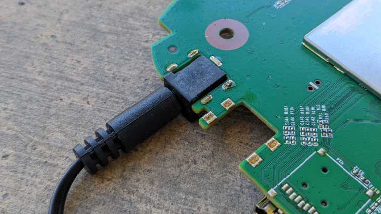
On the hardware side, I soldered sockets to the unpopulated programmer header and then created a programming cable to connect to my FTDI serial adapter (*). For the software, I cloned the “Starter Pack” repository, followed installation directions, and encountered a build failure:

Arduino\libraries\Brzo_I2C\src\brzo_i2c.c: In function 'brzo_i2c_write':
Arduino\libraries\Brzo_I2C\src\brzo_i2c.c:72:2: error: cannot find a register in class 'RL_REGS' while reloading 'asm'
   72 |  asm volatile (
      |  ^~~
Arduino\libraries\Brzo_I2C\src\brzo_i2c.c:72:2: error: 'asm' operand has impossible constraints
exit status 1
Error compiling for board Generic ESP8266 Module.

This looks like issue #44 in the Brzo library, unfixed at time of this writing. Hmm, this is a problem. Reading the code some more, I learned Brzo is used to create I2C communication routines with the IS31FL3741 driver chip controlling the LED array. Aha, there’s a relatively easy solution. Since the time the badge was created, Adafruit has released a product using the same LED driver chip and corresponding software libraries to go with it. I could remove this custom I2C communication code using Brzo and replace it with Adafruit’s library.

Most of the conversion was straightforward except for the LED pixel coordinate lookup. The IS31Fl3741 chip treats the LEDs as a linear array, and something had to translate the linear index to their X,Y coordinates. The badge example code has a lookup table mapping linear index to X,Y coordinates. To use Adafruit library’s frame buffer, I needed the reverse: a table that converts X,Y coordinates to linear index. I started typing it up by hand before deciding that was stupid: this is the kind of task we use computers for. So I wrote this piece of quick-and-dirty code to cycle through the existing lookup table and print the information back out organized by X,Y coordinates.


      for(uint8_t x = 0; x < 18; x++)
      {
        for(uint8_t y = 0; y < 18; y++)
        {
          reverseLookup[x][y]=-1;
        }
      }
      for(uint8_t i = 0; i < PAGE_0_SZ; i++)
      {
        reverseLookup[page0LUT[i].x][page0LUT[i].y] = i;
      }
      for(uint16_t i = 0; i < PAGE_1_SZ; i++)
      {
        // Unused locations were marked with (-1, -1) but x and y are
        // declared as unsigned which means -1 is actually 0xFF so
        // instead of checking for >0 we check for <18
        if(page1LUT[i].x < 18 && page1LUT[i].y < 18)
        {
          reverseLookup[page1LUT[i].x][page1LUT[i].y] = i+PAGE_0_SZ;
        }
      }
      for(uint8_t y = 0; y < 18; y++)
      {
        Serial.print("{");
        for(uint8_t x = 0; x < 18; x++)
        {
          Serial.print(reverseLookup[x][y]);
          if (x<17)
          {
            Serial.print(",");
          }
        }
        if (y<17)
        {
          Serial.println("},");
        }
        else
        {
          Serial.println("}");
        }
      }

This gave me the numbers I needed in Arduino serial monitor, and I could copy it from there. Some spacing adjustment to make things a little more readable, and we have this:

const uint16_t Lookup[ARRAY_HEIGHT][ARRAY_WIDTH] = {
  {  17,  47,  77, 107, 137, 167, 197, 227, 257,  18,  48,  78, 108, 138, 168, 198, 228, 258},
  {  16,  46,  76, 106, 136, 166, 196, 226, 256,  19,  49,  79, 109, 139, 169, 199, 229, 259},
  {  15,  45,  75, 105, 135, 165, 195, 225, 255,  20,  50,  80, 110, 140, 170, 200, 230, 260},
  {  14,  44,  74, 104, 134, 164, 194, 224, 254,  21,  51,  81, 111, 141, 171, 201, 231, 261},
  {  13,  43,  73, 103, 133, 163, 193, 223, 253,  22,  52,  82, 112, 142, 172, 202, 232, 262},
  {  12,  42,  72, 102, 132, 162, 192, 222, 252,  23,  53,  83, 113, 143, 173, 203, 233, 263},
  {  11,  41,  71, 101, 131, 161, 191, 221, 251,  24,  54,  84, 114, 144, 174, 204, 234, 264},
  {  10,  40,  70, 100, 130, 160, 190, 220, 250,  25,  55,  85, 115, 145, 175, 205, 235, 265},
  {   9,  39,  69,  99, 129, 159, 189, 219, 249,  26,  56,  86, 116, 146, 176, 206, 236, 266},
  {   8,  38,  68,  98, 128, 158, 188, 218, 248,  27,  57,  87, 117, 147, 177, 207, 237, 267},
  {   7,  37,  67,  97, 127, 157, 187, 217, 247,  28,  58,  88, 118, 148, 178, 208, 238, 268},
  {   6,  36,  66,  96, 126, 156, 186, 216, 246,  29,  59,  89, 119, 149, 179, 209, 239, 269},
  {   5,  35,  65,  95, 125, 155, 185, 215, 245, 270, 279, 288, 297, 306, 315, 324, 333, 342},
  {   4,  34,  64,  94, 124, 154, 184, 214, 244, 271, 280, 289, 298, 307, 316, 325, 334, 343},
  {   3,  33,  63,  93, 123, 153, 183, 213, 243, 272, 281, 290, 299, 308, 317, 326, 335, 344},
  {   2,  32,  62,  92, 122, 152, 182, 212, 242, 273, 282, 291, 300, 309, 318, 327, 336, 345},
  {   1,  31,  61,  91, 121, 151, 181, 211, 241, 274, 283, 292, 301, 310, 319, 328, 337, 346},
  {   0,  30,  60,  90, 120, 150, 180, 210, 240, 275, 284, 293, 302, 311, 320, 329, 338, 347}
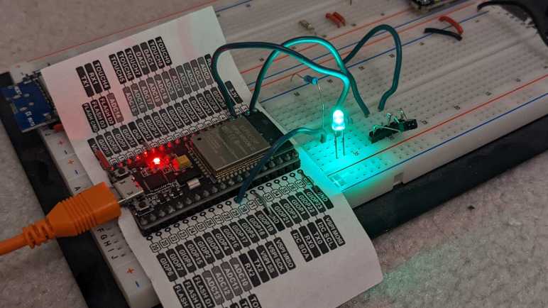
};

This lookup table got Mr. Robot Badge Mk. 2 up and running without Brzo library! I could write that simple “turn on all LED” test I wanted.

The test exposed two more problematic LEDs. One of them was intermittent: I tapped it and it illuminated for this picture. If it starts flickering again, I’ll give it a dab of solder to see if that helps. The other one is dark and stayed dark through (unscientific) tapping and (scientific) LED test equipment. It looks like I need to find two more surface-mount red LEDs to fully repair this array.

In case anybody else wants to play with Mr. Robot Badge and runs into the same problem, I have collected my changes and updated the README installation instructions in pull request #3 of the badge code sample repository. If that PR rejected, clone my fork directly.


(*) Disclosure: As an Amazon Associate I earn from qualifying purchases.

Black and Decker 5-Cup Coffee Maker

A coffee machine for the home kitchen can get very fancy, but not this one. This was the lowest-end, simplest, least expensive model DCM600B available at the store that day many years ago. I’m curious how simple a coffee maker can be inside. As the entry-level product, every expense would have been spared, and I hope to see some engineering creativity to reach that cost-optimized goal.

From the top, there is only one visible fastener. A Philips-head screw in the water reservoir.

With it removed, we can see majority of the path for boiling hot water.

  1. Hot water is pumped up through this pipe.
  2. Which then makes it through this bend in the lid.
  3. Exits here to dribble onto coffee grounds.
  4. Held inside a coffee filter sitting in this cup. Water filters through the coffee grounds, through the filter, out through the hole in the center of this cup.
  5. Which drips into the carafe.

Bottom view with model number DCM600B visible. The power cord was cut some time ago. I no longer remember the reason why, but it is quite apparent past me wanted to ensure there would be no further use.

Two fasteners are visible from the bottom. The first surprise was that nonstandard fasteners were used, I had expected generic screws in the interest of cost.

My screwdriver bit that matched this screw was labeled CR-V 6.

The second surprise was that no screws were hidden under rubber feet. Once the two visible nonstandard screws were removed, the bottom cover flipped open. There were some grates in that bottom cover to release any liquid that might enter this enclosure. There was also a dam that protected electric wire from such liquid.

Judging by residue and this corroded screw, that seepage draining provision came in handy.

I would not have been surprised if the power switch merely wired power directly to a heating element. The machine is actually slightly more sophisticated than that, but not by much.

Removing a few things allowed some untangling of the wire. One end of the power cable is connected to a black wire, presumably ground, connected to one end of the horseshoe-shaped heating element. The other end is connected to a red wire that led to the power switch, which connects it to a blue wire connected to the other end of the heating element via three components. I don’t know what these components are, but the first of these three in series is clamped to the heating tube. Functionally, I infer they sense temperature and would open the circuit when things get too hot, and close the circuit once things cooled down. Such a circuit would implement the “keep coffee warm” feature.

The item clamped to the heating tube is presumably a temperature sensor. It has the following markings:

1504
T3/33
125V10A
150

There is very low resistance across the two terminals at room temperature. I heated it up with the most convenient heat source, which was my heat shrink tube hot air gun. The measured resistance did not appreciably rise as I heated it up, nor did it go open circuit. But I doubt this hot air gun pushed the device to water boiling temperature, so the results are inconclusive. I don’t have the equipment to test electronics behavior at different temperatures, the only thermometers I have are for measuring human fevers and for kitchen baking.

While brewing coffee, water from the reservoir would keep the heating element from getting too hot. Hot water would boil and expand. How did the machine ensure that such water would be sent through coffee grounds instead of back to the reservoir? This cheap and simple ball check valve is the answer. It would not have been a perfect seal, allowing some water back into the reservoir, but it’s good enough for the job.

Disassembled components from the bottom.

I admire the simplistic efficiency of this machine’s design. Here’s a final example: this machine has capacity for five cups of water. How do we prevent the user from overfilling? I would have guessed float sensors and maybe an overflow valve. The design team didn’t need any of that complexity, they cut two holes in the water reservoir to drain excess water out to the kitchen countertop. Problem solved!

BlueAnt Q3 Bluetooth Headset

I’m making slow progress learning to work with surface mount electronics, but I still have a long way to go. This retired BlueAnt Q3 Bluetooth headset is a marvel of miniaturization and a reminder of how far behind the state of the art I am. Even more when considering that, judging by this product review I found online, this device is getting close to ten years old! Since that time BlueAnt seems to have stopped making this product category, with nothing similar currently listed on their page.

This particular unit came to me already disassembled by someone else, but I think its battery was the only notable item missing. The mechanical design is very impressively intricate, integrating several controls that had to be big enough for a human figure to manipulate. But it’s the electronics that really shine.

  1. This is a micro-USB port for charging. It also gives a scale perspective on how tiny everything is.
  2. Speaker
  3. Push button
  4. Dual LED module with a white LED and red LED sharing a single package. I would have expected such a thing to share either a common anode or a common cathode but that’s not the case here. This little yellow rectangle has four pads. One anode and one cathode for each of the two LEDs.
  5. MIC1 and MIC2 are the two microphones used for noise cancellation and other nifty features.
  6. Three-position toggle switch. It is the same size as the power switch used on Mr. Robot Badge. What’s tiny on that circuit board takes a significant percentage of real estate on this one.
  7. I think this curved piece might be an antenna?

Between 6 and 7 we see several unpopulated pads. I don’t know if there are different lines to the BlueAnt Q3 for additional features, or if they represented features that they’ve cut from the product.

Flipping over, we see the following:

  1. IC that runs the show.
  2. Debug headers.
  3. BT1 and BT2 are good candidates for battery terminals. I’m a bit annoyed they didn’t mark them BT+ and BT-. If I were trying to repair this device, I risk reversing battery polarity and damaging the device.
  4. This is a really cool control I hadn’t seen before. The nub sticking out to the right is a switch that can be moved above or below the center position, and a spring-loaded mechanism pulls it back to center once released. In addition to that, the cream-colored center circle might be a push button. It certainly gives the tactile “click” appropriate for a button when pushed. Together they are a completely self-contained unit for up/down/select menu control. I would love to play with it some more, except for the fact that it is tiny. That center circle is only 2mm in diameter, and this device has at least 13 little soldering points holding it on the circuit board. With my current skill level, I would destroy the device trying to remove it from the board. But since this is tiny, I can keep the board and try later once I have better tools. Perhaps a hot plate can simultaneously melt all the solder without damaging the plastic?

Made by Design Ultrasonic Oil Diffuser (120mL)

I’ve seen these oil diffusers from more and more vendors recently, evolving from a novelty item to a mass-produced commodity. Cheap enough that someone may buy one, try it for a while, and decided against it sometime after the store return period. Which was the case for this unit, which was given to me not because I wanted a diffuser (I didn’t) but for me to take apart.

This particular unit has the Target logo and “Made by Design” stamped on the bottom. I recently read an entertaining article about Costco’s “Kirkland Signature” brand, and motivated by that knowledge I went and researched Target’s (much longer) list of brands. Indeed, “Made By Design” was one of them. Not that it matters too much right now (unless I want to buy another) the fact it is available from a house brand just confirms the commodity status of such products.

I put a bit of water in the device, plugged it in, and turned it on without the lid. The water started bubbling (making a mess of my workbench) and some of it dispersed into fine fog.

It’s much neater with the lid on, where only the mist exited a dedicated vent in a soft breeze.

We can see all major airflow elements in this picture.

  1. The circular fan intakes air from the bottom….
  2. That air exits a rectangular chimney in the side of the base. This air circulates around the space between the base and the lid until…
  3. Air enters the fogging area, picking up some aerosolized liquids, then…
  4. Exits out to the room.

Each of the three foam feet hid a Philips-head screw.

Once removed, the base came apart easily exposing its main circuit board. Eight LED modules are visible, as is an IC that appears to run this particular show.

The power socket slid from its position easily, far easier than a recent power socket recovery.

The button board was also easily removed, sliding out from its slot without any fasteners or glue in the way.

Only two buttons are present on this device, with provision for a third. And we can see how the control board can read up to three buttons with just two wires. When pressed, each of these buttons bridge a resistor, so the control board can read the resistance and decipher which button (or combination of buttons) are pressed.

Two more screws allowed me to remove the control board, and I was pleasantly surprised by what I saw: every peripheral is connected to the control board by a JST-XH (or compatible) polarized connector. But even more than that, each peripheral has a color-coded connector. Wow! I did not expect to see that. Color coding makes sense to ease assembly and visual inspection, but stocking separate color connectors usually add cost that manufacturers skimp on.

IR1 appears to be an unused provision for infrared remote control. The heat sink is screwed onto what appears to be a power MOSFET, but the screw is inaccessible while the MOSFET is soldered in place on the board. Unsoldering the MOSFET would be a challenge, because it would be dissipating heat out of that heat sink we could not remove while MOSFET is soldered in place. A curious circular puzzle making it difficult to disassemble, I wonder how it was assembled.

In the bottom corner we see a name “asiamist” and a URL “www.fogger.cn” leading to a company that manufacturers such devices for many different house brands.

The single generic fan serves double duty: a cooling fan for that big heat sink and moving air to disperse the fog. It isn’t driven very quickly, which helps keep the noise down and probably also helps extends its service lifespan.

Finally, the star of the attraction. I know nothing of how ultrasonic devices work and I look forward to taking this apart. I might see interesting and fascinating mechanisms of mystery, or I might find something that physically looks unremarkable and give no sign to how it works.

And it is… option B. The heart of the machine is a little metal disc with the following markings

AM1911
2.45M

and otherwise completely unremarkable. If I didn’t already know it was an ultrasonic transducer I would not have guessed its purpose. I was a little disappointed, but its simplicity also implies I didn’t break anything taking it apart. Would it work if I plug everything back in again?

Yes it does! I stopped this experiment very quickly because splattering water and electronics do not make for a happy mix.

Now I have a problem: I can’t think of a reason why I’d want a fogger, but it is still working and I’d hate to just destroy it. But I also didn’t want to store the device intact as it is bulky and consumes a lot of space. As a tradeoff, I’ll cut out and keep just the “business end” of the diffuser with my new toy the Wondercutter S. It was pretty slow going through the plastic, but much neater than if I had used a Dremel and much safer than manual cutting with an X-Acto knife.

Now the heart of the machine can be stored away in a fraction of the space consumed by the full device, leaving the option to reuse this in a future project.

iRobot Roomba Virtual Wall

An old Roomba retired due to worn batteries had an accompanying virtual wall unit for the user to limit its range of motion. Today I take it apart to see what’s inside. I understand it is functionally similar to an infrared remote control, so I expected to find not much beyond a circuit board with an infrared emitter. There are two user controls: an on/off power switch and a sliding switch to select from one of three distance ranges. The push on/off power switch felt like it had two detents, like how a camera shutter button has an initial detent for focus before pushing all the way to take a picture. This particular virtual wall unit also has something rattling around inside and I’m curious to find out the cause.

Looking at the diagram at the base of the unit, I noticed the zone is drawn as a narrow cone plus a small circular area. This implies two emitters: one directional and one not. Examining the unit we can see where they would be: the directional beam would come out of the small gray “nose” and the omnidirectional beam is cast from the circular protrusion up top.

These beams are invisible to the human eye, but my cell phone camera could pick up a glow from the directional emitter. This glow is stronger when we increase the range of the device via slider up top. My camera didn’t pick up anything from the omnidirectional cylinder. The faint green glow visible in this picture is from the human-visible green LED that indicates the unit is turned on.

Most of the volume and heft came from the pair of D-cell alkaline batteries that are all but extinct in modern electronics.

Fasteners are hidden under each of the four rubber feet.

Here’s the mystery of rattling noise: plastic spacers around two of the screws have broken loose. (Intact at left, broken at right.) At a guess, they broke from the impact of this unit getting dropped on the floor sometime in its life.

At least two circuit boards are visible inside, held by screws.

The most unusual component visible here is a chip hidden under a black blob mounted on a small white circuit board, which is then connected to the large board at a right angle. It is accompanied by several through-hole components.

Flipping it over, we can see the narrow circuit board is just a carrier for the sliding switch that controls the LED power and thus range of the virtual wall. The large board has a series of unremarkable surface mount components. The green power LED and directional infrared LED are mounted directly to this board, and the omnidirectional LED assembly is attached with a pair of wires. We can also see here the ten-conductor connection point for that odd-looking vertical white board with the chip under a blob.

Here’s an explanation for why the power switch felt like it had two detents: it pushes on two separate switches each with their rubber dome. So we felt one, then the other, rubber domes make contact. Looking at the trace, these switches (Labeled SW1 and SW2) are wired in parallel. It seems like a lot of work just for the sake of redundancy, but I can’t think of another reason why it might be designed this way.

The omnidirectional LED seems to be held down by hot glue.

I was skeptical when I was told that isopropyl alcohol helps release hot glue, but I have to admit it seemed to have worked well here. But when the glue was removed, I saw the LED is also held in place by a circular piece of plastic that has been welded/glued in place. Why did they feel the hot glue was necessary? If I wanted to replace the LED, I would have to break this piece of plastic, so I’ll hold off for now. I’m going to save this little omnidirectional LED assembly. I might find a use in the future, and that use might be infrared!

Belkin Play N600 Wireless Router

When wireless routers became commodity electronics, industrial design became a differentiation factor. They used to all be uniformly boxes with antennae sticking out of them, but now they come in many shapes and sizes. There’s definitely a market catering to people who don’t like the look of antennae sticking out. This retired Belkin router was from a line of similar designs, with its antennae completely enclosed inside a slickly designed exterior.

My favorite part of this design is a subtle passive cooling system that did not call attention to itself. Between the main body and the foot is a small gap, and here’s where cooling air can be pulled in from the bottom of the unit.

Normal convection forces would send warm air up to the top of the case, where it exits this slot acting as exhaust. I love it.

Only two fasteners are accessible, one hidden under the bottom label.

Removing those two screws allowed the foot to be removed. The cooling intakes are now clearly visible.

Those two screws also help hold the enclosure together. Of course, there are plenty of plastic clips all around as well.

With the first side panel removed, we can see the main circuit board held between the central plastic frame and the other side panel.

Four more screws and many clips later, all major components have been separated.

The circuit board is not very tightly packed. Metal pieces to the top and the left are its WiFi antennae, set at ninety degrees to each other for mutually complementary reception. I’m sure their shape is an intentional design with tradeoffs versus the traditional stick, but I don’t know enough RF voodoo magic to begin to guess at what’s going on. Speaking of RF voodoo magic… I see no metal RF shields covering any part of this circuit board. I see provisions for them on this board in the form of silvery solder square outlines above and below the chip marked Broadcom, but unused.

Here we see more unused provisions. This router has a single USB port and a single rear status LED. On the circuit board we can see provisions for a second LED, just above the text labeled LED6. Plus provision for a second USB port, with unused pins labeled 5, 6, 7, and 8. Adding a second USB port would require unsoldering this USB connector and replace it with a double-deck equivalent. The LED housing is already all set up for a second LED.

J12 here is weird, it seems to be a 2-pin header being used as an antenna wire guide. If the pins were straight, I would say this was just a hilarious coincidence with the wire getting caught between pins, but the pins have been bent inward at the factory, what other purpose might that serve but to keep the wire in place?

Melnor Garden Hose Watering Nozzle

As a change of pace from electronics teardowns: I’m taking apart something with no electronics at all: my very old garden hose watering nozzle. It’s been leaking for years, which is why I’ve had to turn the faucet off when this is unused. Otherwise, it wastes water dropping out from the front and the back. But recently it started failing in a new way: there is now a horizontal curtain of water when I pull its lever, spraying water everywhere from just behind the spray pattern adjustment knob. It is finally time for this guy to go, but not before I take a look inside.

A single Philps-head self-tapping plastic screw held the spray pattern selector knob in place.

With the selector knob removed, its seal and detent mechanism falls out easily. The white spring-loaded mechanism pushes into dimples in the selection dial for that satisfying “click” when we are lined up for a spray pattern. The rubber seal has lost its flexibility and became rigid with age. It could no longer seal against water pressure, causing this nozzle’s retirement.

Two more screws were visible and promptly removed, but this plastic piece did not release easily. I broke a bit of the lip (visible in upper-right area of the rim) trying to pull it out. No other fasteners or retention mechanism were visible.

If I could not pull it, perhaps I could push it? I started working on the back end. Unthreading the adjustment nut all the way allowed its removal.

Pushing on the thread, the front face popped free along with the piston assembly. A coat of rust clearly designated regions that had years of water exposure.

Inside the handle body.

Inside the front face.

Intact piston assembly.

I could only partially disassemble the piston assembly. In use the rear seal and its washer moves against the piston shaft and thus could be slid off the end. The spring followed easily.

However, the front seal and the X-shaped plastic guide keeping it centered in the cylinder never had to move and now it is held in place by rust. The plastic guide showing signs of abuse of my removal attempt. Even if replacement seals were available, I would not have been able to replace this particular wear item.

The lever hinge pin is riveted in place, requiring a drill to free it.

And finally, the soft handle surround was cut free of the metal core with a box-cutter knife. Doing this reminded me of that scene in Terminator 2 where the T-800 cut off living tissue covering its arm to expose the metal endoskeleton.

Taylor Food Thermometer

This Taylor food thermometer display went blank and stayed blank even when given fresh batteries, so it’s getting the teardown treatment before disposal. It appears to be a design that the company has made for many years with slight variations, here is a close cousin I found on Amazon. (*) I’ve found no mentions of repair instructions or replacement parts, this is a disposable device.

The first thing I wanted to check is construction of the temperature probe. There were two possibilities:

  1. The temperature probe is mostly metal, and the sensor is near where the wire is attached. This would be dependent on a metal with high heat conductivity to carry heat from the tip of the probe to the sensor at its base.
  2. The temperature probe is mostly hollow tube, and wires run the entire length of the probe to a sensor at the tip.

I started opening it up and got this far before slicing myself open on a sharp metal edge.

With a ritual blood sacrifice to the teardown gods, I decided to stop here. It is far enough for me to conclude that possibility #2 is correct and the probe is mostly hollow tube with the sensor at the tip.

Next I started prying against the shiny top surface of the device and found it was merely a cosmetic facade held on with glue and not hiding any fasteners underneath.

Four fasteners were visible behind the display so I started work there.

There is a piezo sound element embedded in the back, and a circuit board inside. Under that black blob is likely a chip that runs the whole show. What struck me are the areas to the left of the blob: there are a few round test points, but many more rectangular pads for components that aren’t there. Are they for calibration? Are they for adjustment? Are they to activate/deactivate features for other products in the lineup? Maybe a combination of all of them?

I see a single screw for the base. Removing that screw freed a small piece of plastic but did not free the entire base. However, it did let me see inside the base and distinct signs of additional fasteners.

Aha, I forgot to check for fasteners hidden under squishy feet.

With those screws removed, we can see the base has no active components. It has the battery enclosure, socket for the temperature probe, and a circuit board for all the switches and buttons to operate the device. All the components appear to be in good shape, I see no obvious signs of damage that might explain why the device stopped working.

The display is a custom LCD unit held on with the squishy conductive stuff I’ve seen before in tearing down electronics but didn’t know anything about. This time I went online and found this electronics StackExchange thread. Which linked to this one. Formally “Elastomeric connector” and less formally “zebra strips” (though a search with those terms also need to have “electronic” in the keyword list or else we’d get stuff about zebra the animal.)

I don’t plan on keeping the circuit board or any of the components on board, but I’ll hang on to the LCD for the moment. If I get around to probing the LCD in the future I’ll need to fabricate my own circuit board to make contact with the zebra strip. I can take this picture showing the connector pitch, but sadly I’ve already lost horizontal alignment reference and that’ll be a problem I have to tackle later.


(*) Disclosure: As an Amazon Associate I earn from qualifying purchases.

Surface Mount Repair Practice with Mr. Robot Badge

Years ago at a past Hackaday Superconference, I had the chance to play with a small batch of “Mr. Robot Badge” that were deemed defective for one reason or another. After a long story that isn’t relevant right now, I eventually ended up with a single unit from that batch with (at least) two dark LEDs in its 18×18=324 array of LEDs. I thought trying to fix it would be a good practice exercise for working with surface-mount electronics, and set it aside for later. I unearthed it again during a recent workshop cleanup and decided it was a good time to check my current surface mount skill level.

I’m missing a few tools that I thought would be useful, like a heat plate or hot air rework station. And while my skills are better than they were when I was originally gifted with the badge, it’s still far from “skilled” at surface mount stuff. (SMD for surface-mount devices, or SMT for surface-mount technology.) One relatively new tool is a dedicated LED tester, and I used it to probe the two dark LEDs. One of them would illuminate with the test probe in place, and a dab of solder was enough to make proper electrical connection and bring it to life. The other one stayed dark even with test probe and would need to be replaced.

Looking in my pile of electronics for a suitable doner, I picked out my ESP32 dev module with a flawed voltage regulator that went up in smoke with 13V DC input (when it should have been able to handle up to 15V DC). This module has a red LED for power and a blue LED for status. I probed the red LED and found it dead, but the blue LED lit up fine. Between “keep looking for a red LED” and “use the blue one in my hand” I chose the latter out of laziness. This is a practice exercise with low odds of success anyway.

Lacking a hot air rework station or a hot plate, I didn’t have a good way to heat up both sides of a LED so there was a lot of clumsy application of solder and flux as I worked to remove the dead badge LED. It came apart in two pieces, so I practiced removal again with the dead red LED on my ESP32 dev module. Once I removed it intact, I tossed it aside and used my newfound (ha!) skill to successfully remove the blue LED in one piece. I might be getting the hang of this? Every LED removal was easier than the last, but I still think a hot air station would make this easier. After I cleaned up the badge LED pads, I was able to solder one side of the salvaged LED then the other. I could see a little bit of green on one side of the LED indicating polarity, so I lined it up to be consistent with the rest of the LEDs on the badge.

I turned on the badge and… the LED stayed dark. It then occurred to me I should have verified the polarity of the LED. Pulling out the LED tester again I confirmed I have soldered it on backwards. Valuable lesson: LED manufacturers are not consistent about how they used the little bit of green on a LED to indicate polarity. So now I get to practice LED removal once again, followed by soldering it back on the correct way. I would not have been surprised if the blue LED had failed after all this gross abuse. On the upside a failure would motivate me to go find another red LED somewhere.

Here is a closeup of the problematic area on the badge. The circle on the right was the LED that just needed a bit of solder for proper contact. The circle on the left represents the scorched disaster zone that resulted from SMT rework amateur hour as I unsoldered and resoldered multiple times. The little blue LED clung on to life through all this hardship I had inflicted and shone brightly when the badge was turned on. I’ll call that a successful practice session.

[Update: I didn’t originally intend to do anything with the badge beyond soldering practice, but I looked into trying to write my own code to run on the badge and successfully did so.]

Window Shopping: Cutra Wondercutter Ultrasonic Knife

During an online video meetup with some makers, I learned that consumer-level ultrasonic knives exist. One member of the meetup was taking theirs apart for some reason I’ve now forgotten, I just remembered his quick demo of the handheld cutting blade cutting through a 3mm thick sheet of acrylic. It wasn’t exactly “hot knife through butter” (maybe cold knife through refrigerated butter) but certainly far superior to what I could do with my X-Acto #11 blade.

I had known of ultrasonic tools in the medical field, specifically dental tools. I also had some idea they existed in the realm of industrial manufacturing equipment. But something I could conceivably buy for my own workbench? That’s news to me. Unfortunately, the person on the video wasn’t able to give me much information to go on, so I started searching for “ultrasonic knife” from my usual list of tool vendors. Unsurprisingly, I got a hit at McMaster-Carr: Item #3415N11 Fast-Cutting Ultrasonic Precision Knife. Visually, this looks like the same device I saw being disassembled at the meetup. But McMaster-Carr didn’t give me very much information on this device, not even some things I consider basic like make and model for further evaluation.

A search for “Ultrasonic Knife” on Amazon would give me several multi-thousand-dollar industrial machines, and also this listing. (*) Titled “The Wondercutter S” it looks right, but this listing felt odd for several reasons. The brand is listed as “MICRO-MAKE” but there’s nothing else by that brand name. There is also a logo on the device absent from the McMaster-Carr listing. It is stylized so I couldn’t quite decipher it to letters, but it is definitely neither “Wondercutter” or “MICRO-MAKE”. This listing didn’t give me the confidence I needed to commit several hundred dollars, despite Amazon Prime guarantees.

Continuing online search, I also got a hit at Home Depot which was a mild surprise. I had not associated the big orange DIY home improvement store with high tech tools. From this listing I got a brand name “CUTRA” which explains the stylized logo I couldn’t read earlier.

Now that I have a brand name, I found its company site and their own product site. It appears to be a Korean company and I finally got the specifications I could sink my teeth into. There were also a lot of demonstrations videos on what this device could do, the one that got my attention was cleaning up supports for 3D printing. I’ve never enjoyed cleaning up supports, and I’ve had a few dangerous close calls with my trusty X-Acto blade doing so. A couple of hundred dollars is a significant investment, but if it saves me a single hospital visit that would make the item worthwhile.

From this site I also learned that Wondercutter was crowdfunded as an Indiegogo project back in 2017. Well, I definitely missed the early bird backer special of $258 USD! I just have to pay retail now. Elsewhere on the site I saw I could order direct from Korea, but they have signed an official distributor for United States: Micro-Mark. Now this is a name I know from my scale plastic model days! I used to be a very good Micro-Mark customer buying Tamiya paints (they’ve all since dried out) and small model-building hand tools (I still use some of them).

Well, at least this explains the mystery branding of “Micro-Make” on that Amazon listing, it was a typo of Micro-Mark. There is actually a Micro-Mark storefront on Amazon (*), but with only a subset of the full catalog. For example, they sell replacement Wondercutter blades (*) but they don’t sell the Wondercutter itself on Amazon. Why would they leave it open for an imposter vendor to take away potential Amazon sales? That’s a curious business decision. Micro-Mark claims to be the exclusive distributor for North America, and I can see they are listed as vendors on sites like Walmart. But I’m not sure what’s the point of going through Walmart (or Home Depot or Amazon) if Micro-Mark is actually the distributor. It seems to make more sense to order one direct from Micro-Mark’s own website.


(*) Disclosure: As an Amazon Associate I earn from qualifying purchases.

Brother TZe Label Tape Cartridge Teardown (Don’t Put Secrets On Your Labels!)

While organizing my workshop, I labeled a lot of things with my label maker (Brother P-Touch PT-D400) and used up a cartridge. A common complaint with these TZe label tape cartridges is that they are really expensive. So now that I have an empty cartridge, I thought I would take it apart to see if I can see anything that justifies its expense. It turned out to be far more sophisticated than I had originally expected, but I still don’t know if I would call its cost “reasonable”. Plus I found an interesting security concern. Don’t use label makers for confidential information!

The only thing we can really see from the outside is a horizontal window designed to let us see how much tape is left. When full, there’s white visible behind the light blue area. That white spool’s diameter decreases as the tape is consumed, gradually running to what we see in this picture where very little white is visible behind the blue.

Looking around the perimeter, I see several little clips holding the lid to the body plus this white tag telling me what label tape is inside. I expect that I would have to cut this white tag along the seam, pop those little clips loose, and it should fall apart.

It did not.

Majority of holding force actually came from these posts that fit very tightly into their sockets, not the clips or the sticker. Dimension precision in injection-molded plastic is directly correlated to cost, so that’s where some of the money went: it’s pretty expensive to keep these posts and their corresponding sockets within the exact dimensions to fit and grip tightly.

After I opened up the cartridge, I see I had drastically underestimated the complexity inside. There are actually four spools, a few rollers, and many guides to keep three tapes of materials flowing properly.

Here are all the components of the cartridge. Multiple spools, and a few springs to maintain tension. I had expected a single spool of tape that gets spit out, so this is far more complex than I had anticipated. There are actually three spools of material: The white adhesive backing, the black ink (with take-up reel), and the clear laminate layer.

Here is a closeup of the clear laminate spool and the white adhesive backing spool. The clear laminate spool has black stripes in this picture because that’s how the cartridge signals the end. There were ~20cm left of this zebra stripe, not that I can think of much I could do with it.

Here is the other side, showing the adhesive backing still usable on what’s left of the white reel. It looks like remaining white backing can still function as double-sided tape if I wanted to put it to work.

The black ink tape was a surprise. It is a pair: a dispenser reel for fresh material and a takeup reel for used ink. What’s super interesting here is that the takeup reel has a clearly legible negative image of everything that has been printed. Unspooling the takeup reel a bit, we can clearly see that my most recent label was for a batch DC buck converters showing their adjustable voltage range and maximum of 5 amps capacity.

A valuable lesson from this teardown: avoid confidential information when using a label maker, because a motivated dumpster-diver can read that information off your discarded empty label tape cartridges.

Window Shopping LovyanGFX

One part of having an open-source project is that anyone can offer their contribution for others to use in the future. Most of them were help that I was grateful to accept, such as people filling gaps in my Sawppy documentation. But occasionally, a proposed contribution unexpectedly pops out of left field and I needed to do some homework before I could even understand what’s going on. This was the case for pull request #30 on my ESP_8_BIT_composite Arduino library for generating color composite video signals from an ESP32. The author “riraosan” says it merged LovyanGFX and my library, to which I thought “Uh… what’s that?”

A web search found https://github.com/lovyan03/LovyanGFX which is a graphics library for embedded controllers, including ESP32. But also many others that ESP_8_BIT_composite does not support. While the API mimics AdafruitGFX, this library adds features like sprite support and palette manipulation. It looks like a pretty nifty library! Based on the README of that repository, the author’s primary language is Japanese and they are a big fan of M5Stack modules. So in addition to the software technical merits, LovyanGFX has extra appeal to native Japanese speakers who are playing with M5Stack modules. Roughly two dozen display modules were listed, but I don’t think I have any of them on hand to play with LovyanGFX myself.

Given this information and riraosan’s Instagram post, I guess the goal was to add ESP_8_BIT composite video signal generation as another supported output display for LovyanGFX. So I started digging into how the library was architected to enable support for different displays. I found that each supported display unit has corresponding files in the src/lgfx/v1/panel subdirectory. Each of which has a class that derives from the Panel_Device base class, which implements the IPanel interface. So if we want to add a composite video output capability to this library, that’s the code I expected to see. With this newfound knowledge, I returned to my pull request to see how it was handled. I saw nothing of what I expected. No IPanel implementation, no Panel_Device derived class. That work is in the contributor’s fork of LovyanGFX. The pull request for me has merely the minimal changes needed to ESP_8_BIT_composite to be used in that fork.

Since those changes are for a specialized usage independent of the main intention of my library, I’m not inclined to incorporate such changes. I suggested to riraosan that they fork the code and create a new LovyanGFX-focused library (removing AdafruitGFX support components) and it appears that will be the direction going forward. Whatever else happens, I now know about LovyanGFX and that knowledge would not have happened without a helpful contributor. I am thankful for that!

Roku Premiere (4620X “Cooper”) Power Socket

When I tear down some retired electronic device, I try to salvage what I know I could reuse and that usually includes the power supply. A few of these salvaged power supplies have already found use, but sometimes I’m hindered by the fact I saved only the power supply and not its corresponding power socket. Sometimes I can replace the connector, but sometimes not. As a result, I’ve resolved to put more effort into saving the matching socket as well.

Which brings me to this Roku Premiere 4620X (“Cooper”) that was given to me for teardown after it was retired. I tried to unsolder its power socket, but I quickly realized I was in trouble. When I put my soldering iron tip on the soldered point and… absolutely nothing happened. Looking at the circuit board I can see there’s a lot of copper tied to ground, which four of five pins on this power socket is attached to. That’s a lot of heat dissipation capacity fighting against my iron’s efforts to melt solder.

I think a hot air rework station might be able to help here, but I don’t have one and my lack of skill means there is a high risk of softening the black plastic as I blast hot air. If I distort the plastic to a point where the power plug could no longer fit, that would defeat the purpose. This concern also definitely ruled out my paint-stripping hot air gun.

I think the best tool for this job is a hot plate designed for installing surface-mount electronics components. Their hot metal surface area could in theory do this work at a lower temperature than blowing hot air. I wouldn’t necessarily need a big one, either. A tiny little one would be enough to do this job.

But I don’t have any of those tools, so I fell back to plan of last resort I call “mechanical separation”. That is my fancy way of saying I whipped out a saw and cut the circuit board around the socket.

Sometime in the future, when I decide I want to reuse this power supply and its matching power socket, I hope to have better tools for the job of separating the socket from its (now much reduced) circuit board.

ESPHome Remote Receiver Test: Simplistic Shooting Game

I salvaged an infrared remote control receiver from a Roku Premier 4620X (“Cooper”) and dumped out some codes using an ESP32 microcontroller running ESPHome software’s Remote Receiver component. This is great, but before I moved on, I ran a simple introduction to actually using it. The “Hello World” of ESPHome remote receiver, so to speak.

The idea is a very simple shooting game. I will add an LED to the breadboard connected to GPIO 18. I will count to five seconds in an on_loop lambda and illuminate the LED using ESPHome GPIO output component. Once illuminated, it will wait for the signal sent by a Roku RC108 remote when the “OK” button is pressed. Once received, I will darken the LED for five seconds before turning it back on. With this very simple game I pretend to “shoot out” the light with my remote.

It was silly and trivially easy as far as shooting games go. Infrared remote controls are designed so the couch potato doesn’t have to aim very accurately for them to work. The emitter sends out the signal in a very wide cone, and the receiver is also happy to receive that signal from within a wide cone. If I am to evolve this into an actually challenging target practice contraption, I would have to figure out how to narrow the cone of effectiveness on the emitter, or the receiver, or both!

But that was not the objective today. Today it was all about dipping my toes in that world before I continued with my Roku teardown. I wanted to keep the hardware trivial and the code simple, so here is the ESPHome code excerpt for this super easy shooting game:

esphome:
  on_loop:
    then:
      - lambda: |-
          if (id(ulNextOn) < millis())
          {
            id(led_01).turn_on();
          }

status_led:
  pin:
    number: 2

output:
  - platform: gpio
    pin:
      number: 18
      inverted: true
    id: led_01

globals:
  - id: ulNextOn
    type: unsigned long
    restore_value: no
    initial_value: '0'

remote_receiver:
  pin:
    number: GPIO36
    inverted: true  
  dump: nec
  tolerance: 10
  on_nec:
    then:
      - lambda: |-
          unsigned long ulTurnOff;
          
          if (0x55AA == x.command)
          {
            id(led_01).turn_off();
            id(ulNextOn) = millis() + 5000;
          }

Roku Premiere (4620X “Cooper”) Infrared Receiver

Looking over the circuit board of a Roku Premiere 4620X (“Cooper”) I saw a lot of things that might be fun to play with but require more skill than I have at the moment. But that’s fine, every electronics hobbyist has to start somewhere, so I’m going to start small with the infrared remote control subsystem.

Consumer infrared (IR) is not standardized, and signals may be sent on several different wavelengths. Since I want to play with the Roku RC108 remote control unit, I needed to remove the infrared receiver of its corresponding Premiere 4620X in order to guarantee I have a matching set. This is a small surface-mount device protected by a small metal shield that I could fold out of the way.

Once the shield was out of the way, I could turn on the Roku and probe its pins with my voltmeter to determine the power supply pin (constant 3.3V) the ground pin, and the signal pin (mostly 3.3V but would drop as I sent signals with the remote.) I then removed this receiver with my soldering iron and connect this tiny part to a set of 0.1″ spacing headers so I could play with it on a breadboard.

In this picture, from top to bottom the pins are:

  • Ground
  • (Not connected)
  • Power 3.3V
  • (Not connected)
  • Active-low signal

I installed it on a breadboard with an ESP32, flashed with ESPHome which is my current favorite way to explore things. In this case, ESPHome has a Remote Receiver component that has decoders for many popular infrared protocols. What if we don’t know which decoder to use? That’s fine, we can set the dump parameter to all which will try every decoder all at once. For this experiment I chose an ESP32 because the of its dedicated remote control (RMT) peripheral for accurate timing while decoding signals. After I get something up and running, I might see if it works on an ESP8266 without the RMT peripheral.

With dump parameter set to all listening to a Roku RC108, I got hits from the JVC, LG, and NEC decoders. And occasionally I would get a RAW message when none of them could understand the signal. If I hold the [up] button, I get one instance of:

[18:55:50][D][remote.jvc:049]: Received JVC: data=0x5743
[18:55:50][D][remote.lg:054]: Received LG: data=0x57439867, nbits=32
[18:55:50][D][remote.nec:070]: Received NEC: address=0xC2EA, command=0xE619

But just the first one. All following hits look like this, and they repeat for as long as I held down the [up] button.

[18:55:50][D][remote.jvc:049]: Received JVC: data=0x5743
[18:55:50][D][remote.lg:054]: Received LG: data=0x57439966, nbits=32
[18:55:50][D][remote.nec:070]: Received NEC: address=0xC2EA, command=0x6699

Then if I press the [down] button on the remote, the first interpreted signal became:

[18:55:52][D][remote.jvc:049]: Received JVC: data=0x5743
[18:55:52][D][remote.lg:054]: Received LG: data=0x5743CC33, nbits=32
[18:55:52][D][remote.nec:070]: Received NEC: address=0xC2EA, command=0xCC33

Then it would repeat the following for as long as [down] was held:

[18:55:53][D][remote.jvc:049]: Received JVC: data=0x5743
[18:55:53][D][remote.lg:054]: Received LG: data=0x5743CD32, nbits=32
[18:55:53][D][remote.nec:070]: Received NEC: address=0xC2EA, command=0x4CB3

Looking at this, it looks like JVC is overeager and doesn’t actually understand the protocol as it failed to differentiate up from down. That leaves LG and NEC decoders. To find out which is closer to the Roku protocol, I started tightening the tolerance parameter from its default of 25%. When I have it tightened to 10%, only the NEC decoder returned results. Even better, each button returns a repeatable and consistent number that is different from all of the others. Even if Roku isn’t actually using a NEC protocol, using the NEC decoder is good enough to understand all its buttons. I used the NEC decoder to generate this lookup table.

Roku Remote ButtonDecoded Command
Back0x19E6
Home0x7C83
Up0x6699
Left0x619E
OK0x55AA
Right0x52AD
Down0x4CB3
Instant Replay0x07F8
Options0x1EE1
Rewind0x4BB4
Pause0x33CC
Fast Forward0x2AD5
Netflix0x34CB
Sling0x58A7
Hulu0x32CD
Vudu0x7788

I think I got lucky this time with the NEC decoder. I had another infrared remote control in my pile of electronics (JVC RM-RK52) and none of the ESPHome decoders could decipher it, just RAW data all the time. Alternatively, it’s possible that remote is on a different infrared wavelength and thus this particular receiver is only picking up fringe gibberish. I’ll put the JVC remote back in the pile until I am in the mood to dig deeper, because right now I want to quickly play with this salvaged infrared system.

Roku Premiere (4620X “Cooper”) Circuit Board

After examining the enclosure of a Roku Premiere model 4620X (“Cooper”) that I took apart, attention turns to the solitary circuit board inside the device. A piece of cast aluminum under its top lid has all the appearance of a heat sink, so the first thing I did was to pop off the thin metal shield to confirm – yep, there’s a microprocessor under there. With a bit of black thermal compound to bridge the small gap between it and the metal shield.

The other metal shield is directly soldered to the board and I couldn’t remove it (nicely) to see what’s inside. So I flipped the board over instead. I see a shield whose shape mirrored the top shield and covers nearly (if not exactly) the same area.

In comparison to its topside counterpart, it has an extra twist in the form of extra metal bridging the center in a “T” pattern. Or maybe a circle with three legs? This must be intentional, but I couldn’t figure out why.

And just for fun, here is the board side-by-side with a Raspberry Pi 4, which has broadly similar specifications of an ARM-powered 4K UHD capable networked device.

Using a cotton swab and some isopropyl alcohol, I cleaned off the thermal compound to read markings on the CPU.

I see two logos: a stylized “M” (MediaTek?) with ARM, and below them the following:

MS09380AMZ-R62-NA1
ATKR524B
1637B

Several connectors are visible around the board, not all of which are used. Starting from the upper left, we have the power connector.

There are five soldered points, but all four along the sides are electrically connected to ground. Only the bottom center point is different, picking up 12V from the AC adapter. Below it is a large round contact point (with a bit of solder) is one of two grounding points for the aluminum heat sink.

To the right is an unpopulated connector also with four surrounding ground points but with three unused electrical contacts. I’m not sure what this would be. My first thought was maybe an alternate video connector, but there aren’t enough pins to be any type of DisplayPort. Composite video or S-Video are too old-school for this 4K-capable video streaming box, so I ruled those out. It is too small to be a pair of RCA jacks for analog audio, so my best guess is a provision for TOSLINK audio.

Next is the HDMI connector, with several meticulously routed differential signal pairs visible.

The final connector on this edge is probably an 8P8C connector for wired Ethernet, with an adjacent unpopulated chip footprint that’s likely to relate to wired networking. Their absence means this particular Roku is WiFi-only.

On the left edge of the board is definitely a switch, electronic schematic symbol for switch and everything. Since there’s already a reset switch on board, this is probably used for a development/test/debug purpose.

On the right edge looks like provision for a USB type-A socket. It may be for similar dev/test/debug purposes, but Roku may have also contemplated the option of a USB port so it can play a slide show of pictures on a USB flash drive. This is a feature I see on many other media boxes.

The bottom of the edge has two antennae, and my RF skills aren’t enough to know what to do with them. A status LED is on the right edge, but I have plenty of LEDs and saw nothing particular special about this one. In between the antennae, though, is a receiver for the infrared remote. I’ve come across similar receivers before, and I always thought “that might be fun to play with” but never did… until now.

Roku Premiere (4620X “Cooper”) Enclosure

I’ve just disassembled a retired Roku Premiere model 4620X, also named “Cooper”. I had expected its enclosure to be just a plastic box, but it turned out to have a few points of interest. The most unexpected item was the Roku fabric tag sticking out the side.

It was clearly a piece of branding, and I thought it was pretty clever how Roku could do that by sandwiching a little piece of fabric into the seam of their enclosure. That would be super simple and inexpensive to manufacture. But then I realized… there’s no seam here! The fabric tag is actually coming out of a dedicated slot in the side of the case. This slot, which is perpendicular to the motion of their plastic injection mold, would have added cost to the process.

And since it’s not sandwiched in an existing seam, it’s not held in place by an existing fastener either. This is a separate piece (or multiple pieces?) of plastic dedicated to a Roku name tag, adding to parts cost and assembly complexity. I thought the Roku fabric tag was a cheap thing to throw in there, but no. This required a very deliberate decision in product design. A little web research found that this is actually a registered Roku trademark. I had originally dismissed it as unimportant, I guess this is why I’m not a hotshot product designer.

A metal plate stamped with “6000000235 A1 REV2” is at the bottom. A small cutout on one edge gives extra clearance for the reset button, and four plastic posts help support the main circuit board. The plate itself was fastened to the plastic enclosure by four blobs of melted plastic.

The four blobs of melted plastic were quickly dispatched with a drill, freeing the plate. There was nothing remarkable on the other side. It seemed to have been stamped out of sheet metal. It is not magnetic, so I am going to guess aluminum. At a weight of roughly 10 grams (about one third of an ounce) it is too light to serve as unnecessary weight designers sometimes add to products for the sake of a “premium feel” heft. It does add a bit of support to the structure, but the enclosure did not feel noticeably flimsier with its removal. Perhaps it adds strength along an axis I didn’t test? There is no mechanical contact with the circuit board, so it is not a heat sink. There are no electrical contacts with the circuit board, either, so it is not an antenna. But it might be an anti-antenna serving as RF shielding. Though RF shields usually have a connection to electrical ground on the circuit, which it lacks. What is the purpose of this metal plate? I’m stumped.

The top plate, in contrast, has an obvious purpose as heat sink for the processor. Its shape hints at a casting process, and it is also nonmagnetic so I’m going to guess aluminum here as well. Imprinted from the casting mold are the markings “6000000233 REV 3 ADC 12 B2” and a circular indicator with seven out of twelve positions filled with a dot and “16” in the center. It probably means something to the people running the manufacturing process but not tome.

I usually see heatsinks from the desktop computer world, where they are precision ground to tight tolerances for optimal contact with the processor. This piece looks to have received no post-processing machining after being cast. Instead, a square of squishy thermal pad takes care of filling the ~1mm gap. It would be less thermally conductive than what is used for desktop processors, but probably just fine in this context. Aside from the raised square section to make contact with the processor, there are two circular posts (upper right and lower left in picture) to electrically ground this piece of metal.

A quick visit by the drill freed this plate as well, and this time its structural support was more noticeable. The lid was pretty flexible once it was removed. It is also a beefier piece of metal at 38g, almost quadruple the weight of bottom plate but still not exactly “heavy”. I doubt the weight is the point of the exercise, so the most likely primary purpose is heat sink for the circuit board.

Roku Premiere (4620X “Cooper”) Teardown

I’ve been gifted two retired Roku devices for teardown. The small streaming stick was straightforward, now it’s time for the far more interesting Roku Premiere. I also have its AC power supply and remote control.

Looking up the model number 4620X listed on the bottom of the case, we find these specifications on Roku’s hardware reference chart:

Device NameRoku Premiere
Code NameCooper
roDeviceInfo.GetModel()4620X
CPUARM Cortex A53 quad core 1.2 GHz
RAM1 GB
Accelerated Graphics APIOpenGL ES 2.0
Max UI Resolution1920X1080
Max Playback Resolution4K UHD, 60fps
HDR Supportn/a
IDK SupportNo

Whereas the streaming stick was roughly analogous to a Raspberry Pi Zero, the 4K UHD capabilities here put this item closer to a Raspberry Pi 4. A more capable piece of hardware that is fed more electrical power as well. Its power supply (model PA-1120-42RU) is specified to deliver 12 volts DC at up to 1 amp.

Unlike a streaming stick, a Premiere can be set in line of sight of the user so its remote control (model RC108) is infrared. I plan to play with this later.

I see a seam around the top of this enclosure, and a bit of prying could release some plastic clips. But they would immediately snap back. I suspect some fasteners are hidden under the bottom, which is a soft rubbery surface that gives the device good traction to resist sliding around.

I had expected annoying strong glue to hold this in place, but it actually peeled off easily. Not as easily as normal cellophane (“Scotch”) tape, more like packing tape or duct tape.

I see my primary target: four Philips-head screws. I also see the reset button through a window in the case, a hard nub on the rubber base helps us push it when needed. Towards the upper left of this picture, we can see another window exposing test and/or debug points.

Those four Philips-head screws were revealed to be self-tapping plastic screws upon removal. Then I resumed working on the lid, and this time its clips could be freed and stay freed.

Once clips were freed, the lid could be removed exposing a circuit board.

There is only one layer to the circuitry, below that is the bottom of the case.

Here are the components laid out.

There were a few features that caught my interest that’s worth a closer look, starting with its external enclosure.

Roku Streaming Stick (3500X “Sugarland”) Teardown

A friend gave me this retired Roku streaming stick to take apart. Before I did, I looked to see if I could do something fun in the software realm and found the Roku IDK. Sadly this device lacks IDK support so it is getting taken apart.

A streaming stick is pretty simple piece of hardware. The device itself has two connections: an HDMI plug to go into your TV, and a micro-USB port for power. A reset button is the lone user input, and a LED the lone user output. The power supply looks like a standard AC powered USB power supply advertised to deliver up to 1A at 5V, but it has Roku branding which is more than what some other devices ship with. This device should also have a radio frequency (RF) remote control instead of the usual infrared, since infrared requires line-of-sight and that won’t work for a streaming stick behind the TV. But I was not given the remote, or I have lost it.

On the back I see a model number of 3500X. Roku’s hardware reference chart lists the following information for 3500X:

Device NameRoku Streaming Stick
Code NameSugarland
roDeviceInfo.GetModel()3500X
CPUARM11 600 MHz
RAM512 MB
Accelerated Graphics APIOpenGL ES 2.0
Max UI Resolution1280X720
Max Playback Resolution1280X720
HDR Supportn/a
IDK SupportNo

Based on these specifications, the hardware within is less powerful than a Raspberry Pi Zero. The latter has a CPU running at a higher speed, double the RAM, and could output 1080p resolution UI. However, video playback on the Pi is not its greatest suit. In contrast, video playback is a Roku’s main purpose, so I assume it has access to video acceleration that Broadcom has limited access to Pi.

Using an iFixit opening tool, I pried against a visible seam on the back and quickly unsnapped six clips holding the enclosure together. The circuit board was removed without fuss.

There’s not a whole lot to see on the back. There is a large IC under the sticker, and an array of test points in the upper left. Probably a debug header for the onboard processor, but that’s beyond my hardware skill today.

A thin metal shield covers most of the front side. Visibly outside the shield is the LED, the reset button, and antenna 1 and 2. Once the thin metal shield was removed, we could see the main processor with the following markings:

Broadcom
BCM43236BKMLG
HE1537 P21
5383606 3 W

To its right are two smaller chips, and to its left, a chip by Samsung whose markings were tall and narrow and very difficult to read.

Here is a Raspberry Pi Zero WH (Wireless Header) next to the streaming stick, a fun comparison as these two share some similarities in functionality. Even if this Roku streaming stick supported their IDK, for projects that do not involve video playback I would probably choose to use a Raspberry Pi instead. Since IDK is not supported, this circuit board is going to electronic waste. This was a quick teardown, as appetizer for the more interesting Roku Premiere teardown.

Window Shopping Roku IDK (Independent Developer Kit)

I’ve been given a pair of Roku streaming devices that were retired from a friend’s household, as they knew I like to take things apart to look inside. Before I do that, though, I briefly investigated what might be fun to do with intact and functional Roku devices. I was quite pleasantly surprised to learn that Roku has recently (announcement dated October 26th, 2021) released an Independent Developer Kit (IDK) for hobbyists to play with Roku hardware. This is different from their official Software Development Kit (SDK), which is available to companies like Netflix to create their Roku apps (“channels”). Many other differences between the IDK and SDK are explained in their IDK FAQ.

The Roku SDK requires a business partnership with Roku, but the IDK is available to anyone who is willing to work at low level in C++ and has a Linux development machine available to the task. No direct support for Windows or MacOS, but as the resulting binary is uploaded through a web interface, theoretically a Linux virtual machine could be used to run these tools. The list of example apps hint at what is accessible through the IDK: the OpenGL ES API, interface to the Roku remote control, interface for audio playback, and interface for video playback. (Including Wildvine DRM-protected content.) And it sounds like an IDK app has pretty complete control of the machine, as only one IDK can be installed at any given time. If it takes over the Roku shell, that implies control over the entire system even greater than possible with SDK-developed Roku channels.

But I couldn’t test that hypothesis due to the final requirement: a Roku device with IDK support. A chart listing all Roku hardware has a row for “IDK Support” and the old devices I’ve been gifted are both shown as “No”. If I really want to play with the Roku IDK, I’d have to go out and buy my own Roku device with a “Yes” listed on that chart. At the moment I don’t see the advantage of buying Roku hardware for this purpose. On the surface Roku IDK appears less compelling than developer support available on Google Chromecast or Amazon Fire TV devices. Or for ultimate openness, we can go with a Raspberry Pi. Maybe I’ll find a reason for Roku projects in the future, in the meantime these two old devices without IDK support will be disassembled. Starting with the smaller streaming stick.