These Aren’t The Frame Buffers You’re Looking For

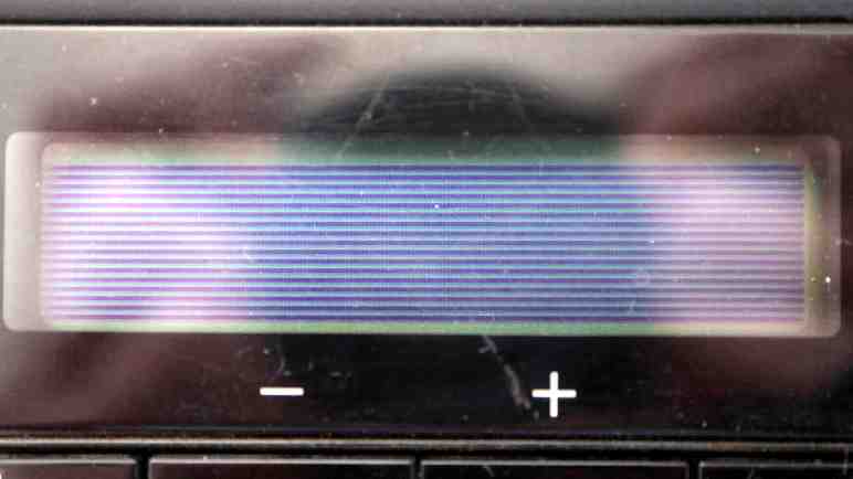
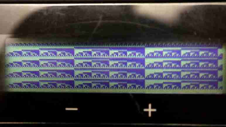
After a small (if not necessarily elegant) enhancement to adafruit_framebuf class, I can use it for basic graphical operations on the bit-mapped LCD of a salvaged Canon Pixma MX340 multi-function inkjet control panel. I then set my sights on adapting it to work with Adafruit’s graphics compositing engine displayio, but that turned out to be more difficult than I had thought.

I don’t know the full history but looking in hindsight I think displayio was optimized for sprite rendering, the most performance-critical part of a 2D game engine. Such a system would support products like Adafruit PyGamer. Not so important for this inkjet control panel LCD, whose refresh rate tops out at just under 14 frames per second. But I thought it would be fun anyway.

Adafruit has displayio drivers for their most popular screens and obviously my LCD is none of them. Looking for an appropriate tool, I found their framebufferio class which takes a frame buffer and returns a display object. Its target usage scenario allows using displayio with a RGB LED matrix, which has resolutions with similar order of magnitude as my LCD. This looks promising.

When I fed framebufferio my FrameBuffer class, I crashed my KB2040 which restarted in safe mode. (Indicated by triple blinking yellow LED.) Annoyingly, when a CircuitPython device crashes and reboots like this, Mu closes its serial terminal so I couldn’t read the error message before it immediately disappeared. I had to bring in a different serial monitor tool in order to see the error:

TypeError: 'FrameBuffer' object does not support 'protocol_framebuffer'

Darn. Looks like the CircuitPython frame buffer object I had been working on, isn’t the CircuitPython frame buffer object expected by framebufferio. If I want this to work, I have to implement “protocol_framebuffer“, but what is it? Clicking on the link brought me to something called circuitpython_typing.FrameBuffer, which forwards to rgbmatrix.RGBMatrix. I added methods to my FrameBuffer-derived class in order to match those listed for RGBMatrix, but that was not good enough.

Digging deeper meant going into core CircuitPython written in C. I found framebufferio/FrameBufferDisplay.c which had this line:

self->framebuffer_protocol = mp_proto_get_or_throw(MP_QSTR_protocol_framebuffer, framebuffer);

I think this is where my error message came from, so the next step is to find more information on the expected protocol which was declared in the associated header file FrameBufferDisplay.h.

typedef struct _framebuffer_p_t {
    MP_PROTOCOL_HEAD // MP_QSTR_protocol_framebuffer

    // Mandatory
    framebuffer_get_bufinfo_fun get_bufinfo;
    framebuffer_swapbuffers_fun swapbuffers;
    framebuffer_deinit_fun deinit;
    framebuffer_get_width_fun get_width;
    framebuffer_get_height_fun get_height;

    // Optional getters
    framebuffer_get_bytes_per_cell_fun get_bytes_per_cell; // default: 2
    framebuffer_get_color_depth_fun get_color_depth; // default: 16
    framebuffer_get_first_pixel_offset_fun get_first_pixel_offset; // default: 0
    framebuffer_get_grayscale_fun get_grayscale; // default: grayscale if depth < 8
    framebuffer_get_native_frames_per_second_fun get_native_frames_per_second; // default: 60
    framebuffer_get_pixels_in_byte_share_row_fun get_pixels_in_byte_share_row; // default: false
    framebuffer_get_reverse_pixels_in_byte_fun get_reverse_pixels_in_byte; // default: false
    framebuffer_get_reverse_pixels_in_word_fun get_reverse_pixels_in_word; // default: false
    framebuffer_get_row_stride_fun get_row_stride; // default: 0 (no extra row padding)

    // Optional -- default is no brightness control
    framebuffer_get_brightness_fun get_brightness;
    framebuffer_set_brightness_fun set_brightness;

} framebuffer_p_t;

This is beyond my current understanding of CircuitPython code. Does it mean framebufferio only works with Adafruit’s own frame buffer objects written in C? Or is this compatible with user-created Python code somehow? Again I tried modifying my FrameBuffer-derived class to fit this signature, but either I made a mistake somewhere or it is fundamentally impossible. I wish I could get finer-grained error message telling me where exactly I failed to support protocol_framebuffer, but I just keep getting the same failure leaving me stabbing in the dark.

After a few hours of fiddling without success, I abandoned displayio compatibility and wrote up this page in case my future self wants to pick up where I left off today. Without displayio I’ll learn what I can from using adafruit_framebuf. First lesson: updating LCD at a high frame rate required task synchronization.

Improve Drawing Via MVMSB For adafruit_framebuf

I’m playing with a LCD screen built inside the control panel I salvaged from a Canon Pixma MX340 multi-function inkjet. I tried using CircuitPython’s adafruit_framebuf library for drawing operations. Out of all supported frame buffer formats, the closest is MVLSB but those bits are in reversed order. I added code to reverse bits, which put a picture on screen but the real solution is to add proper buffer format support.

I was encouraged by adafruit_framebuf‘s description in its documentation: “CircuitPython pure-python framebuf module, based on the micropython framebuf module.” If this library was itself implemented in Python, I should be able to figure something out. Clicking “Edit on GitHub” link on the upper right, I was brought to the GitHub repository for adafruit_framebuf and I quickly found source code file for the module.

At the top of adafruit_framebuf.py are a series of classes, each representing one of the supported buffer formats and implements four static methods: set_pixel(), get_pixel(), fill(), and fill_rect(). I found the implementation for MVLSBFormat and it looks like it’s within my skill level to copy it and reverse its bit manipulation operators to create a MVMSBFormat counterpart. The next problem is: how do I use my custom MVMSBFormat class with the FrameBuffer class? FrameBuffer‘s __init__() assigns a format class in response to initialization parameter, and it raises a ValueError() if it doesn’t recognize the parameter.

That’s when I remembered I am still thinking like a C/C++ programmer and Python doesn’t have a concept of private properties. I could create an instance of FrameBuffer for MVLSB format, and then immediately replace the .format property to point to my MVMSBFormat class. As a C/C++ programmer, this feels extremely icky. Is this the correct Python-ic approach? I doubt it, but I don’t know the right way. So right or wrong this is what I have now.

With my FrameBuffer.format pointing to my MVMSBFormat class, adafruit_framebuf drawing operations render correctly on screen without the need for bit reversal utilities. As a bonus, eliminating bit reversal overhead also meant I could draw text again without encountering “RuntimeError: pystack exhausted“. I think that’s good enough to declare victory with basic bitmap operations and move on to a sprite compositing engine.

Reverse Bits To Draw With adafruit_framebuf

Once I found and fixed a missing command within my initialization sequence, I have gained full programmatic control over the LCD screen of a control panel I salvaged from a Canon MX340 multi-function inkjet. The main point of the exercise was to learn, because it’s a relatively simple black-and-white screen 196 pixels wide by 34 pixels tall and not terribly exciting on its own. Still, now that I know how to send it frame buffer data… what can I do with it?

I’m not interested in re-implementing standard graphics routines myself, so I went looking for one already available. While learning about MicroPython I recall coming across mention of a framebuf utility class for basic graphical operations on a frame buffer. As a fork of MicroPython, Adafruit has a corresponding CircuitPython implementation named adafruit_framebuf so I thought I’d take a look.

One of the frame buffer byte formats supported is called MVLSB. The M stands for monochrome, and the V means each byte represents a vertical column of eight pixels. LSB means least significant bit is the highest pixel, and the most significant bit is the lowest. This is very close to what I have on hand except for the bit order. On this screen, the least significant bit is the lowest pixel and they go up from there.

This is the result of drawing a diagonal line from upper left (0,0) to lower right (195,33). Since bit order is reversed within each byte, each horizontal stripe of data gets rendered vertically inverted from what they are supposed to be.

Drawing text results in gibberish when it crosses stripes. But if I position the text so it sits entirely within a single stripe, the result is legible as vertically inverted text. “Hello Framebuffer” in this case.

I could write some code to laboriously step through each bits in a byte and generate a bit-reversed counterpart value, but since there are only 256 possibilities, a lookup table would be much faster at the expense of a bit of memory. I went online looking for such a lookup table and found one in this Stack Overflow thread: Efficient Algorithm for Bit Reversal (from MSB->LSB to LSB->MSB) in C.

I modified that lookup table from C to Python syntax, and used it to reverse a stripe of frame buffer data before transmitting it to the LCD. Now my diagonal line renders as expected. Unfortunately, text rendering now fails with “RuntimeError: pystack exhausted“. This was unexpected. The lookup table itself would have consumed at least 256 bytes, and there’s an additional 196 bytes of working buffer for me to perform bit reversal on a single stripe. I didn’t think I was skating close to RP2040 limits yet here we are. Also, it’s not a general out of memory error, but specifically about call stack size and the bit reversal mechanism didn’t increase the call depth at all. Weird!

Well, reversing bits was just a hack anyway. The right approach is to add support for this byte format directly so convoluted bit reversal workaround becomes unnecessary. And it restored text rendering, too.

Missing Initialization Command For Frame Buffer Offset On MX340 LCD

I had incorrectly configured asynchronous serial communication parameters between my KB2040 microcontroller running CircuitPython and NEC K13988 chip on a control board salvaged from a Canon MX340 multi-function inkjet. But once I sorted that out (two stop bits, not just one) I could successfully send a full set of frame buffer data to the LCD with minimal transmission failures. This allowed me to follow up on an observation I had from my first test: the vertical frame buffer byte offsets are not as expected.

The pattern I saw via logic analyzer indicated the top 8 pixels of the screen were dictated by sending pixel data with the offset 0x4D to start the sequence. But when I tried doing the same thing with my KB2040, the stripe rendered two pixels lower than expected. This pattern continued for the rest of the screen, with successively lower rows corresponding to 0xCD, 0x2D, and 0xAD. When I decoded frame buffer data captured by logic analyzer, offset 0x6D dictated the bottom-most two rows of pixels. (The least significant six bits are not visible.) However, now data sent to 0x6D is not visible at all. Experimenting with other offsets, I stumbled on the fact I could transmit data to 0x8D and that data would help me fill in the top two rows of pixels. (The most significant six bits are not visible.)

Even though it was unexpected, that was good enough for my next experiment: I changed the program so instead of a fixed value, each byte counts up one. This gave me get a precise delineation and count for all horizontal and vertical pixels. Thanks to this test pattern I am now confident this LCD has 196 pixels horizontally and 34 pixels vertically.

But what about that unexpected offset? The most likely suspect is a mistake in my initialization sequence, and a double-check found the culprit. There was a two-byte sequence 0x04 0x42 in my decoded notes, but I forgot to put that in my KB2040 initialization sequence. Once I put that back in, my LCD frame buffer renders at the expected location. On my to-do list is to play with my initialization sequence, selectively skipping them to see what effect they have on behavior. Looks like I inadvertently started that experiment early! This little side trip also suggested an interesting possibility: that the LCD controller has extra frame buffer memory available, possibly allowing vertical scrolling without re-sending the entire frame buffer.

Without the datasheet, though, that’s mostly an empty thought. It’s more productive to try to pair this display with a graphics library.

I Needed Two Stop Bits To Talk To NEC K13988

I’ve got an Adafruit KB2040 microcontroller connected to a control panel salvaged from a Canon MX340 multi-function inkjet. Using CircuitPython busio.uart, I’m trying to emulate MX340 main logic board with my KB2040, communicating with the NEC K13988 chip on board the control panel hoping to access its capabilities. I saw some initial success, but I had to retry many data transmissions which hinted something was amiss. I forged onward to get more data about what might be wrong.

The first experiment was to test my hypothesis that the first LCD update sent by MX340 main board was a “clear screen” sequence. I sent 0x04 0xF5, the command I suspect to be “start displaying data from frame buffer”, but without transmitting the clear screen sequence of zeroes. I was rewarded by an awakened LCD displaying gibberish, proving the command and “clear screen” data hypothesis.

Pulling up my notes on decoding LCD frame buffer data, I followed that pattern to transmit a single stripe of 0x55 as frame data. Hexadecimal 0x55 translates to binary 0b01010101 and I expected this to show up as four horizontal lines across the screen. The first few attempts failed, with no visible change and no 0x20 acknowledgement byte. Then a transmission went through with visible change and 0x20 acknowledgement, but it looks wrong.

Instead of four horizontal lines all the way across, the line is broken as it hopped up and down across the screen. The fact that it came up on screen at all told me I’m very, very close but there’s definitely a problem. At every byte (vertical slice of 8 pixels) there was supposed to be an alternating sequence of bright and dark, but I see several sections where two white pixels separate black pixels, and less frequently two dark pixels side by side without a white pixel separating them.

What might cause these off-by-one-bit errors? My first guess was that the baud rate sent by KB2040 was a tiny bit off from what the control panel expected, so I tried 250001 baud and 249999 baud but that just made things worse. Even parity and 8 data bits had to be correct or I wouldn’t have gotten this far, leaving stop bits as the final parameter. I changed my busio.uart configuration from 1 stop bit to 2 stop bits and that seemed to have been the answer.

Running with 250000 8E2, I could reliably send five full stripes of 0x55 for a screen full of clean horizontal lines. This makes sense in hindsight. When I examined logic analyzer trace one byte at a time, I wouldn’t have seen anything obviously differentiating between 2 stop bits or just 1 stop bit and delay between each byte of transmission. A mistake that went unnoticed until now. However, I still see the occasional transmit failure, so there might be another bug still lurking. I hope to get more data about it as I continue my experiments.

CircuitPython busio.uart Up and Running, Mostly

After a quick warm-up exercise of verifying activity over expected serial transmission lines, I updated my code to use CircuitPython’s busio.uart to interpret that activity as asynchronous serial data. Based on earlier analysis, I expect to receive data at least once every 9.2ms, so I set up an asynchronous task to constantly process incoming data. The good news is that I saw a constant stream of 0x80 0x40, which was as expected. I had established 0x80 was the value reported for “no buttons are pressed” so I had expected that value to change if I pressed a button. It did not! Apparently key matrix scan code reporting doesn’t start by default.

In order to parrot the initialization sequence decoded by my logic analyzer, I need to write another asynchronous task. This one transmits given data and then wait for the receiver task to see an 0x20 acknowledgement byte before returning. Once up and running and initialization sequence sent, the receiver task started reporting key matrix scan code values. Success!

Up until this point I still had the Neopixel sample code running as a system heartbeat indicator. With serial communication up and running, I thought I’d switch over to using one of the LEDs on the control panel. I created another asynchronous task, this one loops to turn the “In Use/Memory” LED on and off at one second intervals while leaving the “WiFi” LED off. I have already decoded the bit flags necessary to toggle LEDs and I got a LED that blinked for a few seconds.

Then it got stuck.

Debugging indicated that my code got stuck because the data transmission to update LED state never received that 0x20 acknowledgement, which meant the transmit task never returned to caller. I quickly whipped up a timeout mechanism by checking timestamp in a loop. It worked, but then I realized there was already a mechanism built into CircuitPython. So I deleted my timestamp checking loop and replaced it with a single call to asyncio.wait_for().

I needed to write this timeout code and retry transmission for robust error recovery no matter the reason, but I want to know the reason why I never got 0x20 acknowledgement. Maybe there are times when the chip is not listening to my commands? Or maybe there’s a problem in my data transmission? I think it’s very likely the chip isn’t always receptive, but that’s not as important as the discovery there was indeed a problem with my data transmission.

CircuitPython countio For Detecting Activity (Limited on RP2040)

I have a rough idea on how I would use CircuitPython’s asyncio capability to structure my learning project, but jumping straight into async/await in a new platform is too bold for me. I would rather ramp up gradually starting with running a few CircuitPython samples. Once I was satisfied my KB2040 board is generally working as expected, I started poking at project-specific needs. First task: see if I’ve soldered serial communication wires correctly by checking for activity on those pins in reaction to enable pin status. (Toggled via CircuitPython’s digitalio module.) I expect activity on the receive pin when the enable pin is high, and no activity when enable is low. The transmit pin should have no activity in both cases.

I had originally intended to check pin status by polling pins in a loop, which is not guaranteed to catch all activity but probably good enough for an “is there activity” check. Polling in a loop would have been trivial in an Arduino test sketch, but CircuitPython made it just as easy to pull in something more sophisticated: countio module counts rising/falling edges driven by hardware interrupts, which would have taken a bit more work to set up on Arduino. Great! Let’s do that.

I copied sample code from documentation and modified it for my purposes of watching pins D0 and D1, which were default UART transmit and receive pins on my KB2040. I saved my file and promptly got an error telling me I am not allowed to do this on D0. Huh? Re-reading countio documentation I saw a paragraph I had missed:

Limitations: On RP2040, Counter uses the PWM peripheral, and is limited to using PWM channel B pins due to hardware restrictions. See the pin assignments for your board to see which pins can be used.

Reviewing KB2040 pinout reference, I see D0 is also PWM0A and D1 is PWM0B. So they are both PWM-capable pins satisfying the first restriction, but only D1 satisfied the second restriction of channel B. Fortunately D1 on PWM0B is the default UART receive pins, so that’s the one I was more interested in checking status for anyway. And the check was good: when enable pin is high, there is a steady stream of activity on D1. When enable pin is low, activity stops. Good enough to take the next step, connect UART peripheral to those pins.

CircuitPython asyncio For Cooperative Multitasking

I want to apply my CircuitPython lessons to a project that will require importing the busio library to utilize asynchronous serial communication hardware on board a RP2040 chip. This is a pretty common microcontroller scenario, but example projects usually only deal with one direction, either just sending or just receiving. Adafruit’s CircuitPython UART serial introduction only received data and did not send. Things will get more complex as I intend to implement bidirectional communication, and even more so because there’s interaction between the two directions: I need to send data and listen for an acknowledgement.

If that’s the only thing being communicated, it would be easy: one line of code to send data, followed by a line of blocking code to wait for response data. But it’s more complicated in this project because the K13988 chip on the control panel sends key scan matrix reports on a regular basis. (Every ~9ms.) If I wrote my code in the naive way, that wait for response may pick up a key scan matrix report byte instead of the acknowledgement byte. What I need is something that is constantly receiving and processing data, mostly key scan report bytes. After the data sender code runs, it will have to wait on the receiver loop to pick out any acknowledgement bytes as they come through in between key scan reports.

This is doable within an Arduino-style loop(), and I’ve done it before, but I end up with code that’s hard to follow as it rapidly switches between multiple contexts. That’s why I was happy to learn CircuitPython implements the async/await pattern with its asyncio library, which should theoretically allow cleaner code structure. My prior experiences with this pattern mostly centered around JavaScript client/server networking code and not microcontrollers, but never fear, as per usual for Adafruit there’s an excellent guide Cooperative Multitasking in CircuitPython with asyncio putting the pattern in context for microcontroller tasks.

It also highlights an important simplifying characteristic of CircuitPython: it has only a single thread of execution running a single event loop, so there is no concern of race conditions between multiple threads/loops and we don’t have to worry about protecting critical sections. Eliminating concurrency eliminates all the huge headaches of writing concurrent code, at the performance cost of running only a single core. A RP2040 has two cores, like an ESP32, but apparently one core sits idle while the other runs CircuitPython. For this project (and most of my potential CircuitPython projects) a single CPU core will suffice. I’m not going to worry about the lack of dual-core operation until I run into an actual problem that needs it. Right now my problems are simple, like checking to see if there’s any activity on a pin.


Installation note: for most CircuitPython libraries in the bundle, we install it by copying its single corresponding *.mpy file into the \lib\ subdirectory on our microcontroller’s CIRCUITPY storage volume. But asyncio is actually a directory containing multiple *.mpy files and we copy the entire directory under \lib\ so all its components are under \lib\asyncio\*.mpy.

CircuitPython busio For Hardware Serial Communication

For my first nontrivial CircuitPython project, I thought I would try getting a microcontroller to communicate with control panel salvaged from a Canon MX340 multi-function inkjet. Like most microcontrollers, the RP2040 chip at the heart of my KB2040 board can handle asynchronous serial communication via its UART hardware peripheral. Under CircuitPython, this peripheral is exposed by an uart class. It is under the umbrella of busio library, which includes hardware-accelerated communication of popular serial buses I2C, SPI, and asynchronous serial. CircuitPython has several libraries with the io suffix, and given their hardware-focused nature they appear to be a big chunk of the work required to port CircuitPython to a new microcontroller.

One aspects of CircuitPython (and MicroPython) I found enticing is the ideal that I could develop and debug code on my desktop computer and then copy it to run on a microcontroller. Unfortunately this goes out the window when I want to use hardware-accelerated features like busio.uart. Its name clearly announces that it is not trying to act like PySerial on the desktop. If I want to write something that works on both desktop Python and microcontroller CircuitPython, I would have to write an abstraction layer restricted to the small subset of common features I need in my project. Learning how to write such adapter code is on my Python learning to-do list, but it is out of scope for my first CircuitPython project. I’ll stick with busio.uart and develop/debug strictly on microcontroller.

One Python skill area I want to improve is structuring my code to better handle non-sequential events. The relevant scenario today is sending serial data out the transmit pin while simultaneously responsive to serial data coming in over the receive pin. Plus handling when the two interact: for example waiting to receive an acknowledgement after sending data. My earlier serial data filtering tool handled reading from two serial ports by rapidly switching between polling the two ports, but in hindsight, that was not elegant code and it didn’t handle interaction between the two streams. In the search for a better way, I recall Python supported the async/await pattern I’ve encountered earlier in JavaScript and C#. Furthermore, CircuitPython supports some form of the pattern as well, so I’m going to give it another go.

CircuitPython Test Run: MX340 Control Panel

After reading through AdaFruit’s “Welcome to CircuitPython” guide, the obvious next step is to tackle a project to apply what I’ve learned. I do want to apply it to a rover project, but I fear that’s too big of a first step. Looking around at what I have, I decided to communicate with the control panel I salvaged out of a Canon Pixma MX340 multi-function inkjet.

During my teardown I mapped out the pinout of its ribbon cable connector to printer logic board. I then connected my logic analyzer (and other tools) to understand its communication to the best of my ability, with findings summarized here. In theory, all I have to do is to use CircuitPython to tell my KB2040 how to replicate what I observed coming from MX340 logic board, and I will have a control panel I can use for a future project. In practice, I’m sure it wouldn’t be quite that easy but hey that’s the fun part!

Examining my deciphered pinout list, I connected the three pins leading to the NEC K13988 chip on board. Asynchronous serial transmit, receive, and the chip enable pin. I also need to supply +3.3V DC logic power and connect ground, but that doesn’t strictly need to be on the small 1.0mm pitch connector. I found a few capacitors that presented a larger surface for soldering my wires. For this first round I won’t bother wiring up the direct connection to two buttons (Power and Stop) and two LEDs (Power and Alarm) as getting those working should be fairly straightforward for a microcontroller project and I don’t foresee any educational challenges there. I can do that after I tackle the more interesting challenge of CircuitPython serial communication.

Notes on Adafruit “Welcome to CircuitPython”

After getting comfortable with the idea of learning CircuitPython, I began reading Adafruit’s Welcome to CircuitPython starting guide. I found this to be a great introduction and met my expectation for a document helping beginners get started with CircuitPython. That said, my opinion isn’t as good as one coming from an actual beginner! They would be the true test whether Adafruit succeeded.

[UPDATE: I just noticed that there is a lot of overlap between the general welcome guide and information posted under the KB2040 umbrella. However, they’re not identical. The KB2040-specific version had no reason to cover CircuitPython Hardware, and the general version lacked some sections like CircuitPython Pins and Modules.]

The most immediate interface point of CircuitPython is that it shows up as a USB file storage device. We just have to put our code in a file named code.py on the device, and every time we save our changes they will immediately run. This architecture means any device that can edit files on a USB flash drive can be a CircuitPython development tool, and feedback is immediate for instant gratification. This is great for beginner-friendliness! But I’m a grumpy old man set in my ways. I like keeping my source code in a git repository and that means I have to copy my file from my repository to the USB drive. This is probably not a deal breaker and I expect to find a workflow that will work for me, but it did start me on the wrong foot.

While any text editor will work, Adafruit does name Mu as their recommended Python code editor. Advertising itself as a simple Python editor for beginner programmers I thought I would use it at least for the duration of my learning on-ramp. I found it to be a simple straightforward Python editor, supporting not just CircuitPython but also MicroPython and just regular ol’ Python on computers. It felt a bit like what Visual Studio Code used to be, before it got all bloated with features. Notably, Mu is not so overly simple that it became infuriating for me to use, which makes it better than Arduino IDE before version 2.0.

Speaking of Arduino IDE idiosyncrasies, I like the fact CircuitPython handles libraries for a project by putting them in a \lib\ subdirectory. I felt this was more straightforward than Arduino’s package manager, which always felt more complicated than it needed to be and weighed down by a massive catalog of community contributions.

In comparison, CircuitPython doesn’t have as long of a history to build up such a huge library, but Adafruit & contributors have been making great effort covering common needs. Every time I thought of something I might need from a library, a search quickly found one. (The latest: rotaryio to handle quadrature encoders.) So far, so good! What I need now is a learning project putting CircuitPython to work for me.

MicroPython And CircuitPython Are More Alike Than Different

I want to learn how to work with RP2040-based microcontrollers, and I like the idea of working in a high-level language like Python. Or at least, I would like to give it a shot. Reading about Python for microcontrollers quickly run into two names: MicroPython and CircuitPython. Looking around for information on why I might choose one or the other, I found a wonderful comparison guide published by Adafruit. Based on this information, I now feel more comfortable starting with CircuitPython.

For me, the most important piece of background is that CircuitPython is built as a fork of MicroPython, with enhancements focused on beginner friendliness (an Adafruit signature) versus full support for all features. For someone learning to blink a LED, CircuitPython aims to be the best solution. Beyond the basics, intermediate level projects (where I feel I fit) are likely to be served equally well by either platform. Advanced features like threading and PIO are where CircuitPython concedes to MicroPython, but speaking for myself I won’t have to worry about that for a while if ever. And even if I find myself in a situation where I need to switch, I’m comforted by the claim 95% of knowledge will transfer directly between the two platforms.

What will likely swing the decision for most people are software modules they want to pull into their project. And here I think CircuitPython will take the lead for my scenarios. I buy a lot of stuff from Adafruit, and they are likely to provide CircuitPython libraries for those components. So that covers a lot of hardware which also serves as example code to learn from if certain hardware is not explicitly supported. And following my earlier search for a MicroPython web server with WebSocket support, I found that CircuitPython offers a counterpart httpserver which should be sufficient for my rover project purposes. Looks good enough for me to dive on in.

Dusting Off Adafruit KB2040

My latest distraction is a Raspberry Pi Pico W, a promising alternative to ESP32 for a WiFi-capable microcontroller board. After a cursory experiment with a single LED, I’m ready to connect more components to the board to explore its capabilities. Since it’s new hardware, though, there’s always the chance I’ll goof up somewhere and destroy the microcontroller. I don’t want to take that risk because I’m borrowing this particular Pico W. It’s not mine to blow up! Thinking over my options, I remembered that I already had microcontrollers built around the same RP2040 chip: a pair of Adafruit KB2040.

I got my KB2040 as an Adafruit promotion. They typically have something set up to entice us to put a few more items in our shopping cart, and these were “Free KB2040 with $X dollar purchase” type of deal I got across two separate purchases. As the product page made clear, KB2040 was designed for people building their own custom keyboards. So it was built to be physically compatible with an existing board (Pro Micro) popular with that niche. I had no intention of building my own custom keyboard, but I thought the RP2040 chip was worth a look at some point in the future. That time is now.

There are a few tradeoffs of using a KB2040 to substitute a Pico W. The first and most obvious problem is the fact KB2040 doesn’t have the WiFi/Bluetooth chip, so I could only practice aspects of programming a RP2040 before I bring in wireless connectivity. Equally obvious is the different physical form factor, which means a different pinout. I didn’t think that was a huge deal because I’m not trying to install the board on anything that expects a specific pinout. I printed Adafruit’s pinout reference chart and I thought I was good to go, but I wasn’t. While the RP2040 chip lies at the heart of both a Pico W and a KB2040, they have different peripheral chips. This means I’d need a KB2040-specific build of software and it is not on MicroPython’s list of supported Adafruit boards. D’oh! Fortunately, Adafruit supports KB2040 for CircuitPython. Is it close enough for my purposes? I now have motivation to find out.

HP Windows Mixed Reality Salvaged LED Pinout

While doing a bit of work bench clean up, I found the LED arrays I had intended to salvage from my HP Windows Mixed Reality headset teardown. The surface mount LEDs were soldered on flexible circuit boards so they’re a bit too fragile for me to just toss them in a plastic bag. I found a piece of cardboard to serve as a backing and that should help. Before I put them away folded between sheets of cardboard, I thought I’d pull out my LED tester. Here’s what I found out about their pinout, in the hopes such information will be helpful for future project planning.

The two long strips came from handheld controller location beacon rings. Their shapes are symmetrically mirrored between left and right hand controllers, but they both use the same electrical connector. I saw a small arrow and decided that was pin 1, but it didn’t seem to connect to anything? Pin 6 is the common positive power supply, and pins 2 through 5 are grounds, one for each of four strings. Each string of LEDs are wired in parallel, so 3V is enough to start illuminating them with 20mA shared across all LEDs. There are resistors visible on board so current limiting seems to already exist if I’m ready to crank up the voltage. The LEDs are labeled D1 through D32. I had guessed these 32 LEDs would be evenly divided among 4 strings for 8 LEDs each, but it’s actually two strings of 7 and two strings of 9.

Connector Pin#LED StartLED EndLED Count
2D26D327
3D19D257
4D10D189
5D1D99

Using my mini hot plate I also salvaged the cable PCB connectors. I don’t know if I will use them, but I have the option to do so if I want. At the moment I’m not sure how I might utilize these two very irregularly shaped string of LEDs.

The two short strips came from visor LCD backlights. I wanted to keep the entire backlight display but it was so thin and delicate I failed to disassemble them intact. These LED strips are my consolation prize. Two identical units, one for each eye. Four pins on the connector for two LED strings, but again they are not equally sized. The inner pair powers a string of 6 white LEDs in series, around 17.1V DC for 20mA. The outer pair powers a string of 7 white LEDs in series, around 19.9V for 20mA. I don’t see current limiting resistors here so something else will have to keep things under control.

I thought about using my hot plate to pull these connectors from the flex circuit board as well, but decided to use scissors to cut off most of the flex circuit board and keep the connectors attached. I think this pair of ex-backlight LEDs will work well as PCB side lights, once I can think of a good design for a light-up PCB holder.

Instant Print Toy Camera

A few months ago I learned of digital cameras with integrated thermal printer for instant photo printing. As toy cameras aimed at kids, they have colorful exterior and low price to match. I decided it would be fun to get one. Play with the novelty for a while, then take it apart to learn its electronic guts. Perhaps it can be modified to satisfy one of my friend Emily’s suggestions for my Sawppy rover: instead of a robot arm with scientific instruments, maybe I can build a robot arm with a selfie camera. And with this design, I can instantly print the photo to share!

There are multiple vendors selling different implementations of the same basic concept. I decided on this particular unit (*) for two reasons. First, because it was the cheapest offering of the day and second, it has a camera sensor that can swivel 180 degrees to switch between front-facing (normal use) and back-facing (selfies). The swivel implies a long flex cable, and that should make rover integration easier.

(Picture of toy camera taken by serious camera.)

A lot of accessories came bundled inside the box. Starting with five rolls of thermal paper to feed lots of prints. A pack of color markers let us perform colorization by hand, and a USB type A to type C cable for charging its internal rechargeable battery. Even a neck strap was included!

The camera enclosure was surprisingly well built. I had expected a few simple piece of ill-fitting injection-molded plastic, but it turned out to be more sophisticated than that. The eyes are separately molded pieces of white plastic instead of the sticker I had expected from product listing pictures. The ears are likewise separate pieces, as they are molded in a soft material. No weird plastic flashing and all pieces fit together well. This is pretty amazing quality considering the price point. I’ve paid more for stuff from Harbor Freight that weren’t made as well as this camera. I will be sad to break open the case later, but not enough to dissuade me from my original plan.

I got this device for its instant-print photo capability, but it can also record videos and there’s even a “Hungry” game that’s a weak implementation of the immortal snake game. It reminded me that, as primitive as the screen may be by modern standards, it is generations ahead of the black-and-white LCD used in classic Nokia brick phones.

(Picture of toy camera accessories taken with toy camera then printed by toy camera. Then the serious camera was used to take this picture of the print.)

Photo image quality and print quality were about as expected, which is to say quite poor and appropriate for an inexpensive toy. Certainly Canon won’t lose any sleep over this thing. But it’s definitely good enough to tell what the picture is supposed to be, and its unashamed low fidelity has an unique charm of its own. Given the price point I really can’t complain.

After playing with it for a few hours, print contrast was noticeably faded compared with earlier prints. I first thought maybe the device was designed fully expecting kids to get bored and lose interest quickly, and thus designed with a short service life in mind. But that’s inconsistent with bundling five rolls of paper! It then occurred to me I should try recharging the battery, and that turned out to be the answer: a topped off battery restored the full (if not very wide) range of contrast. Print quality a direct function of battery voltage? Wow. This thing is so spectacularly simplistic it has become its own special kind of awesome. It’s fun, I like it!


(*) Disclosure: As an Amazon Associate I earn from qualifying purchases.

Search For Pico W Web Server Led To MicroWebSrv2

One of the bare minimalist examples I saw while readingConnecting to the Internet with Raspberry Pi Pico W” was a simple HTTP web server. It only serves a single page which is represented by a string embedded in the source code. This is obviously not going to work for anything serious.

Fortunately, the popularity of ESP8266 and ESP32 pioneered an ecosystem of web servers suitable for running on microcontrollers. Many of which have already been adapted to run on the Pico W, as the new hotness on the block. They all meet the primary requirement: Serving static files on board microcontroller flash storage, rather than strings embedded in source code. This is important because I want to update them without having to touch my web server files, and second because I don’t want to hassle with string escape and other inconveniences of embedding HTML/CSS/JS syntax inside valid C or Python syntax.

Most of these web server options were written in Arduino or another C-based framework like ESP-IDF, but a few of them were written in MicroPython so I thought I would look at those first. Beyond serving static files, many of them have routing and associated mechanisms for dynamic server-side responses. Several such frameworks said they’re modeled after Flask, which I’ve played with before, and makes sense in a Python context.

But the one feature I would like is web socket support. I want to try porting my micro Sawppy interface to such a system and that uses web sockets to communicate between the cell phone browser acting as remote control and the microcontroller driving my mini rover. This surprisingly eliminated almost all of the candidates. I found only MicroWebSrv2 for MicroPython compatible web server framework with web socket support.

I am intrigued after a cursory glance over MicroWebSrv 2 README. Especially the claim that MicroWebSrv2 can run on desktop computer Python as well as microcontroller MicroPython. In my earlier development efforts for micro Sawppy interface, I wrote the server-side code twice. Once in NodeJS (JavaScript) as a stub to help me develop on the desktop, and again in ESP-IDF to run on an ESP32. It would be great if I can have a single chunk of Python code that handles both cases. I have to review my code to see what other support infrastructure I would need. The first one off the top of my head is a JSON parsing library, which is included in MicroPython, a good start.

Notes on “Connecting to the Internet with Raspberry Pi Pico W” eBook

After getting my bearings with the “Raspberry Pi Pico Python SDK” eBook, I checked out the Pico W-specific “Connecting to the Internet with Raspberry Pi Pico W“. This volume is even smaller at 49 pages, fitting for an quick introduction to potential of Pico W connectivity. It felt to me like the word “Connecting” in the title is quite literal: this title covers how to establish a connection and not much else on what to do after you connect. Perhaps the authors believed that networking APIs are common with existing platforms. So maybe once we get a Pico W set up enough to connect, everything else will be the same as existing general resources out on the internet? That seems unlikely but maybe a valid stance for an introductory title.

But while the word “Connecting” might be literal, the word “Internet” is not. This book actually goes beyond Pico W’s WiFi connectivity and also covers its Bluetooth LE capability. BLE is not typically used to connect to the internet. It appears the Pico W is also capable of Classic Bluetooth, but this book doesn’t spend much time on that beyond mentioning it was possible.

This book also covers each concept twice: once with the C/C++ SDK, then again with the MicroPython SDK. Seeing them side by side really brought home the fact MicroPython code is generally easier to read. But sadly, the language can only do so much. Bluetooth LE is full of esoteric overhead that needs to be configured no matter the language. An uninformative barrier against beginners trying to learn the technology. While reading one particular example’s MicroPython code in the PDF, I got tired trying to parse BLE minutiae and it occurred to me… I don’t remember reading anything equally dry in the C section. I scrolled back up and that’s when I realized the book authors gave up: there was no C section. Instead of cluttering the book with a bunch of code dealing with C overhead plus BLE overhead, they just said the example code is on their GitHub repository. With a URL for the C developers who care to go wading through it all.

This book tried to cover WiFi, Bluetooth Classic, and Bluetooth LE connectivity enabled by a Pico W over its non-W counterpart. And cover those topics via both C and MicroPython languages. That’s a lot of ground to cover in 49 pages, resulting in a book that feels more like a Getting Started pamphlet. Which is a valuable resource! It was just less than what I had hoped.

Notes on “Raspberry Pi Pico Python SDK” eBook

I’m playing with a borrowed Raspberry Pi Pico W, and thought I’d play with MicroPython on it. That software platform seems to have support direct from Raspberry Pi, which is always promising. I thought perhaps it might even get equal billing with the traditional C-based platform! Well, as soon as I opened up Raspberry Pi Pico Python SDK ebook I knew they were not equal. Despite the usual warning not to judge a book by its cover or length, the fact is there are 54 pages in the Python SDK ebook which is barely 10% of its counterpart C SDK ebook‘s 523 pages.

But I don’t necessarily see that as a bad thing. The advantage of a smaller book is that it’s easier for people to read through and absorb, which aligns with the goal of having Python on a microcontroller to begin with. The book frequently refers the reader to the C book for details not specific to the language, such as details on working with the programmable input/output (PIO) blocks. Writing PIO code is little different from writing in assembly language, and a challenge I intend to tackle sometime in the future.

I was happy to see the prebuilt MicroPython distribution binary for Raspberry Pi Pico W was generated by MicroPython organization, instead of a separate fork maintained by Raspberry Pi. This should mean features are introduced in step with the rest of the MicroPython ecosystem and not lagging behind waiting for someone else to integrate upstream changes.

Another item I was happy to see was a Visual Studio Code extension to ease working with MicroPython. MicroPico, formerly Pico-W-Go, promises a lot of convenience over using a serial terminal like PuTTY, which was what I did before. I’ve become familiar with VSCode so I’ll use the extension first, but people without such affinity have other options like the popular Python IDE “Thonny” and a command-line based “rshell” tool that should be useful for scripting.

Trying MicroPython Again This Time On Raspberry Pi Pico W

I’ve borrowed a Raspberry Pi Pico W for experimentation. I’ve verified it could easily integrate into Home Assistant via ESPHome. (Which is now somewhat misnamed as it works for more than just Espressif ESP chips…) For my next set of Pico W experiments I decided to give MicroPython another try. I tried MicroPython earlier on an ESP8266 and it was not all smooth sailing. Looking for an existing solution to my problem was actually the reason I stopped my MicroPython experiment and found Home Assistant and ESPHome! So this is sort of coming full circle.

The main reason I wanted to give MicroPython another try was the fact Raspberry Pi foundation listed C and MicroPython SDKs side by side as software development platforms for Pico and Pico W boards. This implies MicroPython is treated as a first-class citizen and supported directly from the source. Will actual reality live up to this implication? I don’t know yet but I’m willing to find out. This is also why I’m trying MicroPython before investigating Adafruit’s CircuitPython for the board. As much as I love Adafruit, direct manufacturer support is very compelling.

The obvious criticism of MicroPython is runtime performance. I will have to see how much of a problem it would actually cause for my projects. I’m cautiously optimistic runtime performance will not be a hindrance for two reasons. One, hardware peripherals can handle most performance-critical tasks asked of a microcontroller, and that will largely be the same whether overarching high level application code is in C or in MicroPython. What if there isn’t an applicable hardware peripheral on the RP2040 chip? That leads to the second reason: RP2040’s programmable input-output (PIO) capability. Proven to be adept handling tasks that would otherwise need to be written in low-level interrupt handler code, if it can be implemented that way at all. Sounds like a potentially fun playground to see if reality lives up to theory. I’ll start with the PDF published by Raspberry Pi to guide curious Python developers to Pico W.

Easy To Get ESPHome On Pi Pico W

After borrowing a Raspberry Pi Pico W board to play with, I had many ideas I wanted to try out. The first test was Home Assistant support via ESPHome, and this was a success. In fact, I think getting ESPHome started on a Pico W is even easier than doing the same on their namesake Espressif boards.

A tremendously useful feature of ESPHome is the ability to perform updates over WiFi. This over-the-air (OTA) capability means every ESPHome-powered node in a Home Assistant network can be updated wherever they are around the house, no need to bring them back to a computer with a USB cable (or bring a laptop with USB cable out to them). However, this only works after ESPHome is already running on board, which means initial ESPHome setup on a microcontroller still require a USB connection to install a compiled binary file.

For ESP8266 and ESP32 board, this means connecting it directly to the computer running Home Assistant which can get complicated depending on how Home Assistant is set up and whether its ESPHome plug-in can access USB ports. Alternatively, it can be installed by an ESPHome web tool. Or we can install Espressif’s esptool flash utility on a computer. So this is a solvable problem.

But a Pico W has an even easier way: do it on any modern computer, no software installation required. Because when we hold down the “BOOTSEL” button upon powerup, the Pico W presents itself as a generic USB storage device, to which we can copy the compiled binary file (it has a *.uf2 extension) and the Pico W is off and running. Very nice!

As is typical microcontroller practice, my “Hello World” is to connect a LED to my Pico W and toggle it on/off from Home Assistant. I saw an onboard LED, labeled GPIO25 on a pinout chart, and thought I would use that. When that didn’t work, I looked closer and realized I had mistakenly referenced the pinout chart for a Pico (not W) and Pico W’s onboard LED is actually connected to its WiFi chip instead of 25. Oops! It’s not clear to me where pin 25 was routed on a Pico W, so I switched gears: I connected an external LED with current-limiting resistor to pin 15. And since the board was already running ESPHome firmware, I could do an OTA update to use pin 15 instead.