MX340 Print Head Maintenance Assembly Range of Motion

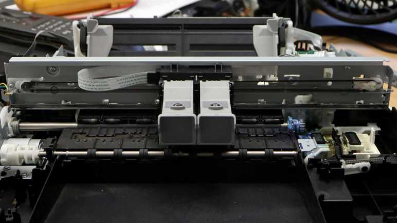
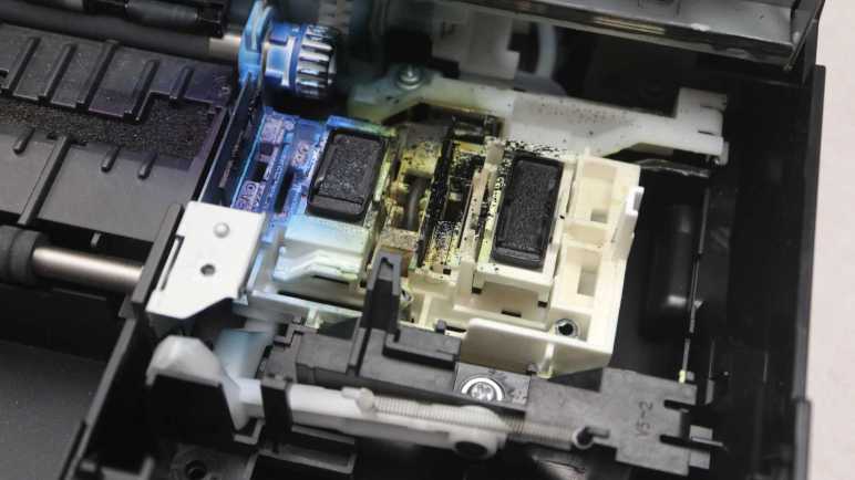
I’ve been playing with the print head carriage mechanism of a Canon Pixma MX340 multi-function inkjet, manually sliding it back and forth. I found no driveshafts conveying motor rotation, but I did find one lever it would push when at a specific position. The carriage also manipulates an ink-splattered assembly that I believe to be responsible for keeping the print heads in good working order.

The carriage pushes the maintenance assembly via its vertical tab on the far right, the only portion high enough to directly touch the carriage.

When the print carriage is absent, a spring pulls this assembly down and to the left. Here it is in the retracted position.

It can slide up and to the right at a ~45 degree angle for approximately 1cm. A small tab (circled in red) held back a section corresponding to the color ink cartridge so it is not raised as high as the rest of the assembly.

Beyond this point, the assembly only sides to the right with no further vertical movement. During this motion, the color ink cartridge subsection is allowed to rise up to join the rest. This right-most position, where the assembly is at its highest, corresponds to the print carriage parked standby position.

The two dark rectangles probably help keep the ink from drying out between print sessions. To the left of each of those two rectangles is a corresponding wiper blade. But if this assembly always moves in sync with the print head, there would be no wiping action.

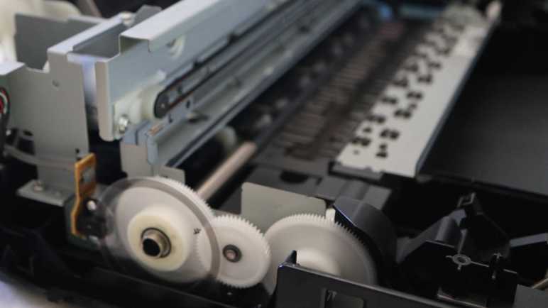
Wiping is made possible by a spring-loaded latch. Here’s the maintenance assembly again in its highest right-most parked position as shown above, but at a different camera angle. The spring in the center of this picture pulls the assembly down and to the left.

As the print carriage moves left, the assembly is pulled left. It barely got past the 45-degree down-and-left transition before the latch (circled in red) blocked further movement. This blockage keeps this maintenance assembly in place while the print carriage continues moving left, and this difference in motion lets the wipers work.

The top of the latch reaches up towards the print carriage, high enough to be engaged by a tab on the carriage between the two ink cartridge slots. Ink cartridges were removed from this picture for a better view.

Once the wiping action is complete, the carriage moves further left and pushes the latch down.

This allows the maintenance assembly to slide the rest of the way down, retracting the two wipers away from their corresponding print heads.

Now that I have knowledge of how this assembly moves, I’ll take a closer look at its components.


This teardown ran far longer than I originally thought it would. Click here to rewind back to where this adventure started.

MX340 Print Carriage Motor And Actuation

I’m looking at the print carriage (“X-axis”) mechanism on my retired Canon Pixma MX340 multi-function inkjet, working to determine what that motor might do in addition to moving print cartridges (and their integrated print heads) back and forth across a sheet of paper. I’ve established it has linear encoder feedback for closed loop control over its entire range (32.5cm) of motion. I know the paper feed (“Y-axis”) motor does a lot more than just feed paper, what else might the print carriage motor do?

One pulley for the print carriage toothed belt is mounted directly to motor output shaft, with no gearbox or other mechanisms, so it’s not driving anything else on this end.

I had thought perhaps there would be a shaft for power transmission connected to the other belt pulley, but that search came up empty. The pulley is mounted on a sliding mount under spring tension so it could absorb mechanical shocks to the carriage system. There were no means to convey rotational power.

Looking for interactions beyond direct power transmission, I noticed a lever not far away.

It pokes through to the front, where it can be engaged by the print carriage.

Manually sliding the print carriage around, I found the lever is pushed by the print carriage when it is 2cm away from the right side edge. I won’t know what this lever does until further disassembly, but based on its position, I expect it is a way for the print carriage (X-axis) motor to shift something in the gearbox turned by the paper feed (Y-axis) motor.

And now that I’m thinking about it… there’s a chance the print carriage “parking brake” pawl does double duty. When the print carriage is in its rightmost parked position, the pawl can fully extend to keep the carriage in its parked position. When the carriage is slightly away from its parked position, the pawl hits the back of the carriage and could not fully extend. When the carriage is in the paper printing area, that pawl could fully extend again. When I take the gearbox apart, I’ll have to keep my eyes open to see if it does anything clever with a partially extended pawl.

But that’s not until later when I take apart that gearbox. More accessible right now is the print head ink maintenance assembly, which is also actuated by the print carriage.


This teardown ran far longer than I originally thought it would. Click here to rewind back to where this adventure started.

MX340 Print Carriage Range of Motion

Before I remove the print carriage motor assembly from my retired Canon Pixma MX340 multi-function inkjet, I thought it’d be a good idea to better understand its motion and how it interacts with the rest of the machine. I found a little “parking brake” for the print carriage, and that was a good start to help me dig deeper.

The print carriage moves two ink cartridges together. One for cyan/magenta/yellow color inks marked “C” and another for black ink marked “B”. Each cartridge has an integrated print head that is replaced whenever the cartridge is replaced. The carriage is attached to a loop of toothed belt, turned by a DC motor. Like the paper feed motor, there’s an optical encoder to provide feedback for closed-loop motor control. Except here it is a linear strip instead of a round disc, read by a sensor buried somewhere inside the carriage.

Here are some close-up pictures of the encoder strip and motor belt drive, showing details at either end.

On the left (as viewed from the front of the printer here) side, the encoder strip is held in tension by a small spring. The left side toothed belt pulley is directly mounted on the motor output shaft, a direct-drive system with no intervening gears.

On the right side, the encoder strip is held against spring tension with a small stamped sheet metal hook. The right side toothed belt pulley is held in tension with its own spring on the back side of the assembly.

The belt pulley tension spring is visible towards the lower left corner of this picture. During normal operation, I could see some horizontal motion (roughly 1-3 mm) in this spring assembly whenever the print carriage started moving, and it likely continues moving in less-visible ways afterwards as the print carriage changes direction or speed. In contrast, the encoder strip tension spring never moves, as expected for something serving as reference.

On either end of the encoder strip, a big circle is present beyond the line pattern. I initially thought this served as some kind of “end of the line” marker, an optical replacement for a physical homing switch. (Precedent: its scanner module uses an optical marker.) But I no longer think so due to two observations. The first is the 34cm width of the line pattern, wider than the print carriage’s maximum range of motion of 32.5cm which means the sensor inside the print carriage never has to move beyond the line pattern and would never see the big circles.

Without physical homing switch or special encoder strip markers, how would the system calibrate carriage position upon startup? Watching its startup sequence again, it appears the control board runs the carriage slowly in one direction until it bumps up against the end. Encoder feedback determines when it could move no further, at which point the process is repeated in the other direction. Proof of actual physical contact is visible as smears of grease left by the carriage on either end of its track.

After checking out the far left and far right limits of this mechanism, I started looking at what else it might do (beyond printing) in between those ends.


This teardown ran far longer than I originally thought it would. Click here to rewind back to where this adventure started.

MX340 Teardown Phase 3 Begins with Print Carriage

I’ve wrapped up my second pass exploring the paper feed motor of my retired Canon Pixma MX340 multi-function inkjet. Capturing data from its quadrature encoder reporting rotation motion had to be done while the system was still in a running state, and I think it’s the last useful data I could extract at my current skill level. Thus this marks the transition point between phase 2 and 3 of my original teardown plan. I will switch focus from electronic probing of phase 2 to mechanical disassembly like in phase 1. The main difference is while I still prefer to keep things in a running state for as long as I can, maintaining functionality is now less critical.

The most obvious target for starting phase 3 is the print carriage assembly, or “the X-axis” in my mind. Sitting on top of all remaining mechanical bits, it carries the two ink cartridges (“C” for colors cyan/magenta/yellow and “B” for black) with their integrated print heads across the printing area as well as a print head maintenance/parking area to the right. After seeing how the paper feed motor was linked to many other mechanisms in addition to feeding paper, I had expected to see similar clever multi-use of the X-axis motor and surprisingly didn’t find additional gears.

Speaking of that paper feed motor, I’ve taken my first step to unraveling its mysteries: it actuates a “parking brake” for the print carriage: A small white plastic pawl that extends (left picture) against the print carriage edge to keep it in its parked position, and retracts (right picture) to allow print carriage movement.

This pawl is connected to a shaft in the paper feed motor gearbox, but not rigidly. So when the pawl reaches one endpoint or another, the underlying shaft continues turning. This will loosen as the system wears, but (1) this geometry can tolerate a lot of wear and still do its job and (2) it has outlasted the service life of this machine so it was evidently good enough.

This pawl was retracted by the first 1800 encoder count rotation when the system powered up, and it was extended with the final 1800 encoder count rotation when the system goes into standby. There are many additional 1800 moves as the printer runs, so I doubt this parking pawl was the sole purpose of 1800 rotations. Certainly a useful related functionality, though.

Once carriage moves beyond its parked position, this pawl will no longer limit carriage movement. It will still move along with its loosely-attached shaft. If it should try to extend, though, it will hit either the flat back of the carriage or empty air depending on position within its full range of motion.


This teardown ran far longer than I originally thought it would. Click here to rewind back to where this adventure started.

Canon Pixma MX340 Paper Feed Motor Round 2 Summary

I’ve had my head in the world of quadrature encoder counts for so long I almost forgot to get data on how they corresponded to the real world. Now with “8640 encoder count per revolution” jotted down, I think it’s a good time to wrap up this chapter of exploration. I started with only the knowledge that this Canon Pixma MX340 multi-function inkjet would turn its paper feed motor even when not actually feeding paper. What is it doing? And while I have to wait for further disassembly for all the answers, I now know more about the control system than I did before.

Given presence of the quadrature encoder, this was a closed-loop control algorithm that adjusted power sent to its DC motor based on position reported by the encoder. Plotting encoder position vs. time reinforced my guess this is primarily a position-based system (“turn 1800 counts”) and less of a velocity-based system (“turn at 1800 counts per second”).

Though there is a velocity control aspect to the system. Plotting motor velocity vs. time added more information: unlike a hobby servo motor, this system doesn’t try to hit the target position at its maximum speed. Some motions are slower than others, but it’s not yet clear to me why some motions are faster than others.

Even though the system appears to be a position-based system with a high resolution encoder wheel, there is a small range of error tolerance. I saw frequent moves of 1800 encoder counts, but sometimes I saw only 1799 or 1798 that the system must have deemed close enough. It aligns with observed deceleration behavior where it seemed to deliberately err on the low side. Consistent with a desire to avoid the overshoot correction headaches of dealing with gear backlash.

Along with this understanding of system behavior, I also have a set of decoded quadrature reports in the companion GitHub repository. This chapter of exploration was interesting on its own, and it would be even better if the captured data becomes useful future reference, but that is yet to be determined.

This marks of my teardown phase 2, onward to phase 3.


This teardown ran far longer than I originally thought it would. Click here to rewind back to where this adventure started.

Captured CSV and Excel worksheets are included in the companion GitHub repository.

MX340 Line Feed Encoder Likely Delivers 8640 Counts Per Revolution

I’ve written down motions I decoded from a Canon Pixma MX340 multi-function inkjet as it went through various states, hoping that information will help me understand its mechanical internals when I take the print engine apart. However, that information was in terms of quadrature encoder counts. I also need to know what they are in terms of physical rotation.

Earlier, I took a close-up picture of the encoder wheel and its many very fine lines. Far too fine and far too many for me to contemplate counting them by eye.

When I had the quadrature encoders connected to my oscilloscope, I determined the sensor runs on 3.3V DC and it is only energized when the print engine is active. Trying to manually push some gears around would risk getting my fingers caught if it started running. But I can’t get any data during idle periods because the sensor receives no power when idle.

Solution: unplug the encoder from the system mainboard, and supply my own 3.3V DC to the sensor. An Arduino Nano has a convenient pin for supplying 3.3V DC.

I turned the gear train manually with my finger to turn the encoder wheel one full rotation, and saw the Arduino declare it had seen 8646 steps. This seemed like a very unlikely number, so I tried again and got 8652. A few experiments turning the gears back and forth determined my finger is far less precise than the encoder. Every time I move the gear and try to move it back to the exact same place, I would end up off by a margin of plus or minus 10 counts.

Given this error margin, I decided I’ll have to take a guess as to encoder wheel resolution. Since this is a rotation encoder, I decided it likely worked in terms of degrees. (Versus, say, radians.) Looking at the range of values I got, 8640 came up as a good candidate as it factors into 360 times 24. 24 encoder counts per degree seems like a useful number, easily dividing into halves, thirds, quarters, etc. as needed.

I can take this number and convert my earlier motion decoder output into degrees. For example, I saw many quick movements of 1800 encoder counts. At 24 encoder counts per degree, that means 1800/24 = 75 degrees. I’m not 100% confident of 8640 counts per revolution on this encoder, but if I’m wrong, 8640 should be close enough for my immediate needs. Good enough to wrap up this chapter of exploration.


This teardown ran far longer than I originally thought it would. Click here to rewind back to where this adventure started.

Captured CSV and Excel worksheets are included in the companion GitHub repository.

Motion Decoder Output Summary

I’ve created a small Arduino sketch that rapidly polls the quadrature rotation encoder of a Canon Pixma MX340 multi-function inkjet and parse that long stream of data into a concise list of movements. I hoped it would help me break down what the print engine is doing. At the moment I won’t be able to translate this data into actual printing functionality, that would come after I correlate these motions to what I’ll discover upon further mechanical teardown.

timestamp,count,min_us_enc
16,1799,28
3785088,2701,36
4262908,-1800,-29
4407660,-1799,-28
7253384,28019,36
11663472,2699,36
11917992,-2699,-38
12176620,-15000,-68
13994420,1800,28
16146804,-1799,-28
16290108,1799,28
16441336,-1799,-28

My tool recognized 12 movements in the system power-up sequence.

  • 7 of them are movements of 1800 encoder positions, at a fast speed of ~28 us/enc. 3 in the positive direction, 4 in the negative direction. (In this system, negative is the direction of paper feed during actual printing.) Some of them are closely paired: negative immediately following positive, but some are interspersed with other motions.
  • 3 of them are movements of 2700 encoder positions, at a slower speed of ~36 us/enc. 2 in the positive and 1 in the negative direction. The second positive 2700 move is immediately followed by the -2700 move.
  • 1 long movement of 28020, at a speed of ~36 us/enc similar to the 2700 movements.
  • 1 long movement of -15000 at a slower speed of ~68 us/sec.

Looking at the system stand-by sequence, I see much of the same components in the list of 15 movements. (It’s not pasted here but available on the companion GitHub repository.)

  • 9 x 1800 @ 28, 5 positive and 4 negative.
  • 2 x 2700 @ 36, 1 positive and 1 negative.
  • 1 x 28020 @ 36
  • 1 x -15000 @ 68

But there were two unique to the stand-by sequence:

  • 1 x 251200 @ 28, a very long roll.
  • 1 x -25120 @ 28 that immediately followed.

I had expected the standby sequence to have unique movements related to putting away the ink cartridges, so these two are good candidates. Other than that, I was surprised to see it repeated much of the same movements as the power-up sequence. I had expected to see something unique during power-up related to getting the ink cartridges ready, but apparently not. Perhaps “get ink cartridge ready” doesn’t occur until the actual printing sequence, which is much more complicated.

  • -49720 @ 24
  • -1310 @ 160
  • Rocking back and forth with 4 x 1800 @ 28.
  • -22421 @ 19. Both the gear and paper sensors changed state during this movement. Did the 4×1800 engage a mechanical clutch or something? I have to look for that.
  • 3000 @ 20
  • -12300 @ 20. (The gear sensor changed state again somewhere in here.)
  • 6200 @ 36
  • -1200 @ 28

Then a long list of 82 x -961 @ 38 movements, each corresponding to the print head putting down a line of ink. Around the 72th iteration, the paper sensor changed state as the bottom edge of the sheet fed beyond the paper tray where the sensor lived. After the 82nd single-line movement, there was another sequence to eject the printed sheet.

  • -3475 @ 20
  • -12905 @ 14
  • -3282 @ 38

Very interesting there were three separate movements in the paper feed direction, at three different speeds.

  • 2700 @ 36, our old friend returns.
  • -1600 @ 29

That’s a lot of movements unique to printing a page. I’m not sure I could link them all to specific mechanical functionality, but at least I’ll have this data on hand as reference when taking this gearbox apart. Better to have it and not know what it means, than to not have it and wishing I did later when the gearbox is in pieces. But right now, I want to map these encoder counts to physical movement.


This teardown ran far longer than I originally thought it would. Click here to rewind back to where this adventure started.

Captured CSV and Excel worksheets are included in the companion GitHub repository.

Simple Debounce Improved Motion Decoding

My current Arduino project is to translate a quadrature encoder’s positions over time into a series of movements, in the hope it would help me understand the inner workings of a Canon Pixma MX340 multi-function inkjet. Trying to keep the project simple, it was simpler to calculate “microseconds per encoder count” (shortened to us/enc below), which is the reciprocal of velocity “encoder count per unit of time”. I think it’ll still have all the information I need. I graphed output from my first draft sketch and it looked like a promising start.

The first problem I want to tackle is noise introduced by the encoder bouncing back and forth between two adjacent values. For example, 1799 then 1800 then back to 1799. This happens because the motion control system could not (or deliberately chose not to) hold the motor at a precise location, allowing it to move around a bit. Since these small bounces aren’t very frequent, they work out to very large us/enc values. Without any processing, the raw plot results in lots of noise in the orange line that doesn’t correspond to any actual movement on the blue line.

To keep my code simple, I’ve been resisting solutions that require me to implement a long history buffer, wary of bugs as I traverse the buffer. I’ve been able to get away with tracking a single history point so far, but in order to recognize bounces, I need to track a second history point to know if I’m just bouncing back and forth between the two history records. As expected, maintaining double the history entries approximately doubled my code complexity, but at least it’s still simpler than implementing a circular buffer or anything along those lines.

The results were worth it! A bit of debounce code eliminated all obvious noises, leaving me with a much cleaner output so I can get a better understanding of this system’s behavior.


This teardown ran far longer than I originally thought it would. Click here to rewind back to where this adventure started.

Captured CSV and Excel worksheets are included in the companion GitHub repository.

Motion Decoder Fail: Zero Delta Between Two Samples

I have wired up an Arduino Nano to a retired Canon Pixma MX340 multi-function inkjet, reading the position reported by a rotary motion quadrature encoder in its paper feed motor gearbox assembly. I want to learn how that mechanism worked, and thought it would be helpful to process raw encoder data into a list of movements undertaken by the mechanism.

Looking at the graph I plotted earlier, this looked pretty straightforward. I added code in my Arduino sketch to poll encoder value in a tight loop and, when two consecutive readings have zero delta between them, treat that as a stopped segment between two movements.

This approach did not work at all! But its failure taught me more about this system’s behavior.

First lesson: as the print carriage moved around, it jostles the whole frame enough for this paper feed encoder to bounce one or two counts off target. I don’t know if it’s impossible/impractical to move this motor system by a single encoder position, or if the control system just decided it wasn’t important enough to bother. Either way, there are small drifts that were too small for me to see in my earlier graphs but would falsely break up zero-delta periods.

A closely related observation: the motor decelerates as it approached its target position, and it doesn’t always hit its target precisely by the time it coasted to a stop. (This is assuming a move of 1798 counts was intended to be a 1800 count move.)

Speaking of that coast phase, the graph shows it can take 20-30 milliseconds before everything comes to a stop. This is a problem, because the Arduino is polling encoder fast enough that it will see the same value multiple on consecutive polls. So if I’m deciding based on zero delta between two readings, it would prematurely conclude the gear train has stopped when it was merely at the very beginning of acceleration or the slow tail end of deceleration.

After one deceleration, the system might immediately start accelerating to execute another motion. One example is visible as the second and third movement in the graph above. From Arduino Nano’s perspective, the delta between two consecutive readings never reached zero between those two movements. Maybe the printer control board decided “slow enough” and started the next move before things actually stopped, or maybe the Arduino is not polling fast enough to catch that brief moment of zero rotation.

I had a laugh at how my system managed to poll encoder value at a rate that is simultaneously too fast and too slow. But the conclusion from these new observations is clear: I can’t get away with just two encoder samples and look for a zero delta between them, my code will have to base its decisions on more reliable factors.


This teardown ran far longer than I originally thought it would. Click here to rewind back to where this adventure started.

Captured CSV and Excel worksheets are included in the companion GitHub repository.

Quadrature Decode MX340 Print

I’m fascinated by the print engine inside a Canon Pixma MX340 multi-function inkjet, there’s a lot I don’t understand but at least it felt like some level of understanding is attainable. Processing a lot of periodic encoder value reports, I saw its standby sequence was longer but not terribly more complex than the power-up sequence. But that’s not the main business of an inkjet print engine. Its business is printing!

Here’s a trace from printing a page, a process that took just under two minutes. (~110 seconds.) And wow, I see a lot of activity. The long shallow slope in the latter half of this graph is where actual printing was in progress, though the shallow slope line visible here is misleading.

Zooming in to that section, the actual motion is visible as a periodic advancement of a bit less than 1000 encoder counts, then held steady as the print carriage moved across to lay down ink. Then it advances another <1000 counts, and so on. This section appeared to be a single long shallow slope only because I had packed too many data points into a single graph and important detail has been lost. I zoomed into the graph at various locations and didn’t discover other artifacts, but I am still wary of drawing too many conclusions from visual inspection of this graph.

Despite that caveat, it’s pretty clear that preparatory work took more time than the actual printing process with ink on paper. This chart also tells me the photo interrupter sensor sampling wires are functioning correctly. Since paper is actually fed, this chart showed activity on the paper presence sensor (blue line) and the gearbox sensor of yet-unknown purpose (orange).

I think I’ve reached limits of the “dump periodic data to Excel, look at graph” analysis method. It was an interesting and easy way to make my first pass on analyzing this data, and it informs my goals for the next pass.


This teardown ran far longer than I originally thought it would. Click here to rewind back to where this adventure started.

Captured CSV and Excel worksheets are included in the companion GitHub repository.

Quadrature Decode MX340 Standby

I’ve got an Arduino Nano connected to the internals of a Canon Pixma MX340 multi-function inkjet, specifically the quadrature encoder reporting on rotational motion of the paper feed motor gear assembly. After capturing the power-up sequence, I pressed the button again to capture the power-down standby sequence.

This standby sequence took twice as long as the power-up sequence, 18 seconds versus 9. Almost 11 seconds were spent rolling backwards relative to printing feed direction, traversing about 248,000 encoder counts. Eight times more than the backwards roll during power-up, which traversed ~31,000 encoder counts. That long rearward roll was followed by a forward roll for ~25,000 encoder counts.

During this roll, there were no paper motion and the print carriage sits in the parked position. What effect could this roll have? At the moment, my only guess is something preparing the ink cartridges to sit for a while. It would make sense for the power-up sequence to prepare the ink cartridges for use, and then for the standby sequence to prepare them for storage. Trying to figure out the details of this preparatory work is on the to-do list for later this teardown.

Besides that very long motion, there are several small movements back and forth. Looking at the data, I can see the times and duration differ between them, but each of those smaller movements traversed 1800 encoder counts. Reviewing the startup sequence, most of those small movements were also 1800 encoder counts. This is interesting. I will have to determine how many degrees of rotation corresponds to 1800 encoder counts, then look for a mechanism that corresponds to such a rotation during later disassembly. This little detail should be easier to understand than the actual printing process.


This teardown ran far longer than I originally thought it would. Click here to rewind back to where this adventure started.

Captured CSV and Excel worksheets are included in the companion GitHub repository.

Quadrature Decode MX340 Startup

Whenever I turn on my Canon Pixma MX340 multi-function inkjet, I immediately hear motors whirring and I had always been curious: I haven’t even tried to print anything yet. What is it doing? Now that I’ve retired the machine and slowly taking it apart, I want to get some information hopefully leading to some answers. I have attached an Arduino Nano to two photo interrupter sensors and the quadrature encoder reporting position of the paper feed motor gearbox assembly. The Nano watches those sensors and report on their status every 10 milliseconds to a serial port as a list of comma-separated values. Thanks to the “everything is a file” nature of Linux, I could run “cat /dev/ttyUSB0 > capture.csv” and I had a file I could import into Excel.

Here is the startup sequence that has long intrigued me, in the form of an Excel scatter chart. Horizontal axis is the time stamp. This graph covered about 9 seconds with a data point every 10ms, resulting in dots densely packed into a line. Vertical axis is the encoder counter value, with the encoder as a gray line maxing out at almost 32000 counts. (Getting a number for count per rotation is on the to-do list.)

The two photo interrupter sensors did not change state throughout startup.

Due to the way I wired up the quadrature decoder, positive values on on this counter correspond to rotating the paper feed backwards. I usually think of printing as advancing forwards on the Y-axis, so this is reversed from that I would have chosen if I had known. But now that it is connected, I don’t care enough to fix this minor issue. If it starts causing problems I can flip the two wires and reverse their direction.

The fact this plot appears to be a series of straight lines tells me the motor does not vary its speed (significantly) once it is in motion.

Zooming on the initial set of movements, I see an acceleration curve before it reaches that speed, and there’s a deceleration curve at the end of each movement. My eyes did not perceive acceleration and deceleration, so this exercise is already telling me things I couldn’t pick up with my own eyes. I can also see the first two movements here are both backwards, but the second movement has a gentler slope reflecting a slower speed. Another difference I could not see with eyeballs.

Zooming in on a different part of the graph, this is the point of maximum backwards travel. On the big graph I saw a small bump on either side of the peak, now I see the motor decelerated to a stop before immediately accelerating back up in the same direction, only to decelerate to a stop again before going in the opposite direction. It then slowed down again to a stop before resuming in the same direction at a different speed. Both of these pauses are extremely short, only a few milliseconds if that.

What did that motion accomplish? In fact, what did any of these motions accomplish? I don’t have answers yet, but I’m excited I’m peeling back at least the first layer of this onion. Next: power down standby sequence.


This teardown ran far longer than I originally thought it would. Click here to rewind back to where this adventure started.

Captured CSV and Excel worksheets are included in the companion GitHub repository.

Canon Pixma MX340 Paper Feed Motor Round 2

I’m slowly taking apart my retired Canon Pixma MX340 multi-function inkjet, and I’ve wrapped up my second pass examination of control panel electronics. Now I will switch attention to its paper feed motor assembly. First of all, calling it the paper feed motor is an understatement, I just don’t have a better name. Looking at gears and shafts on my first pass, I knew it is linked to several other mechanisms beyond feeding paper. I got a close look at how it can open the paper tray door at the front of the machine, but everything else is still buried out of sight at the moment.

They are still buried because I paused physical disassembly in order to ensure the machine remain in a running state. This was very useful as I probed electronic control and communication signals while it was running live. I gained far more insight this way than I could have if I couldn’t run the machine. I learned a lot about the document feeder, the scanner, and how the main board communicates with the control panel. After all that, though, I’m close to exhausting everything within my current skill level to understand. But I think there’s one or two more things I can do before I pick up the screwdriver again.

I want to record paper feed motor mechanism’s behavior. I can see with my eyes it turn forward and backwards multiple times at different speeds. There’s a sequence that runs upon power up, another one when it goes into standby, and naturally there is much more when the machine prepares to actually put ink on paper. I want to quantify that motion more precisely than what I can see with my own eyes. This way, in the likely event the machine stops running as a result of future disassembly, I have something to reference. Correlating them with mechanisms that probably won’t run by the time I disassemble the machine far enough to get to them. I need to quantify exactly what I want to record, then go look for tools that can help me do it.


This teardown ran far longer than I originally thought it would. Click here to rewind back to where this adventure started.

Canon Pixma MX340 Control Panel Round 2 Summary

I’ve been poking around the control panel assembly of a Canon Pixma MX340 multi-function inkjet. An examination of data sent to its LCD module was the final piece of information I had expected to extract when I started “Control Panel Round 2. This post will summarize what I found, with links to specific posts for more detailed reference.

Electrical

The control panel is connected to the main board with a long flat cable with twelve wires. Five of those wires are related to power supply: One 5.5V DC feed a single LED, a 3.3V DC supply for everything else, and three ground wires. Four wires enable direct main board control of four control panel elements: two buttons [Power] and [Stop], and two LEDs [Power] and [Alarm]. That leaves three wires for communication with the NEC K13988 chip on the control panel. See connector pinout post.

The NEC K13988 chip controls the remaining 2 LEDs on the control panel, has a matrix of wires to scan through the remaining 27 buttons, and passes display data onward to the LCD screen. Details at NEC K13988 chip pinout post and LCD connector pinout post.

Communication

Three wires for communication between main board and NEC K13988 chip consists of a single wire for [Chip Enable] and two wires for bidirectional communication. The protocol is 250000-8-E-1 asynchronous serial for both wires.

  • Main board commands are always two-byte sequences, each command acknowledged by the NEC K13988 with a single byte 0x20.
  • Main board bulk data transfers are announced with 0x06 for first byte of the two-byte command and the second byte indicates length of data transfer in number of bytes. This has only been observed for updating LCD screen bitmap, with five transfers of 196 (0xC4) bytes. After 0x06 0xC4 is acknowledged by a 0x20, 196 bytes are sent and another 0x20 acknowledgement at its conclusion. This post decoded a single frame using Excel.
  • Main board commands with 0x04 as the first byte are LCD module commands. NEC K13988 will forward the second byte to the LCD.
  • Main board commands where 0x0E is the first byte are LED commands. NEC K13988 will update illumination of [In Use/Memory] and [WiFi] LEDs based on two of the bits in the second byte.

In addition to 0x20 acknowledgements, the NEC K13988 sends a single byte reporting button matrix status every ~9.2ms. 0x80 means no buttons are pressed. Any value other than 0x20 or 0x80 will be one of the button matrix status reporting scan code listed in this post.

Commands

Lacking any reference material on these components, I don’t know the full meaning of most of the commands decoded and recorded by my Saleae Logic 8 analyzer. Some were correlated with observable behavior and listed above, but the rest remain opaque unknowns.

List of posts that go into more detail on commands associated with each machine state, along with some notes on timing pauses seen in logic analyzer captures:

Future

Sometime after this MX340 is completely torn down, I may try to repurpose this control panel assembly for a future project. I will start by playing back all of the commands recorded above and see if the control panel responds as observed. If it doesn’t, then I have to go back to my Saleae Logic captures and try to replicate the pause timing between commands. If that still doesn’t work, I have failed to capture something important.

If it works, I can try to gain more insight into those opaque commands. I can omit a command and look for changes in system behavior, then repeat for each opaque command. Or I may decide such investigation is not worth the trouble, and just play back those commands as-is while I focus on other aspects of the project. We’ll see what the future holds.

Up Next

This concludes “Control Panel Round 2” and I’m ready to move on. My next target is the paper feed motor assembly.


This teardown ran far longer than I originally thought it would. Click here to rewind back to where this adventure started.

Canon Pixma MX340 Control Panel LCD Data Decoded

I am examining communication between NEC K13988 chip and LCD embedded controller on board the control panel of a Canon Pixma MX340 multi-function inkjet. There are five wires between them, and I have candidate roles for all five after running the printer and looking at their behavior with a Saleae Logic 8 analyzer. Armed with this information, I can configure the Saleae Logic SPI decoder module.

Selecting channel numbers for data, clock, and enable was straightforward. I had to go back and look at the waveform some more to determine the next few options: enable is low when active and there are 8 bits per transfer. Clock is also low when active, and data is valid on clock trailing edge. (With active low clock, trailing edge is the low-to-high transition.)

That left one unknown: does this system transfer most significant bit first, or least significant bit first? Saleae SPI decoder says most significant bit (MSB) first is standard, so I tried that first. I compared decoded data against what I saw before and saw no resemblance. I then flipped the decoder over to treat least significant bits (LSB) first, and jackpot! Decoded data matches byte-for-byte.

Looking at scenarios for system power-up, LCD screen update, and LCD sleep/wake, the pattern is clear. Every time the main board sent a two-byte command to the K13988 where the first byte is 0x04, the K13988 passes the second byte on to the LCD as a command. For LCD update bulk transfers, where the first byte is 0x06 and second byte is length of transfer, the command itself is not passed along but all bytes transferred afterwards are passed on to the LCD as data.

The question this raises is: do I have the correct setting? Perhaps the asynchronous serial communication between main board and K13988 was supposed to be decoded as MSB first, and the match here is merely a “two wrongs made a right” situation. I thought about it and decided the octal number pattern visible in button matrix scan code report wouldn’t exist if decoded as MSB first, so LSB first must be the correct setting.

LCD PinK13988 PinRoleNotes
128SPI Chip SelectActive Low
226Chip EnableActive High
327Command/DataLow = command
High = data

Valid on first clock trailing edge
(low-to-high transition)
49SPI ClockActive Low

8 bits per transfer
510SPI MOSI DataLeast significant bit first

Valid on every clock trailing edge
(low-to-high transition)

It’s great when observations from different parts of the system align! It gives me confidence my notes here aren’t entirely gibberish. As a practical matter I don’t expect to put this knowledge to use, since I don’t plan to extract this LCD screen from its control panel assembly. I can only imagine one scenario where it might make sense to do so: if I want to update this LCD at a higher frame rate, I can decouple it from the K13988 and hook it up to something else with higher SPI clock speed. I doubt that will happen. I’m more likely to use another display, especially if I have its datasheet to know how much higher I can run the SPI clock. I lack such technical information for this screen. I only have information on what I can characterize based on change in measurable behavior, and it’s time to wrap it up with a summary.


This teardown ran far longer than I originally thought it would. Click here to rewind back to where this adventure started.

Canon Pixma MX340 Control Panel LCD Pin Assignment

Tracing through the control panel circuit board of a Canon Pixma MX340 multi-function inkjet, I found five communication wires between its control chip and LCD screen. While I was soldering wires to tap into that data bus, I hypothesized what they might be. My best guess was four wires for SPI plus an analog voltage wire to control display contrast. For my initial captures, I set Saleae Logic to analog mode and ran through scenarios similar to what I used to capture data between main board and control panel. The analog voltage hypothesis was quickly disproved: these are all digital signals of either 3.3V DC or ground.

Setting my capture settings back to digital, I started over from the beginning. At the moment I plugged in its power cable, four out of five wires went high.

When I pressed the power button, the first detected activity was the fifth wire going high. This pin stayed high until I pressed the power button to drop the system into standby mode. From this I inferred LCD pin 2 (red wire, logic analyzer channel 2) is passing through the “Chip Enable” signal. One mystery down, four to go.

Here’s a single-byte command sent to the LCD telling it to go to sleep. LCD pin 4 (green wire, logic analyzer channel 5) looks like an active-low clock signal, pulsing eight times to send a single byte. LCD pin 1 (yellow wire, logic analyzer channel 4) was dropped low just before the clock started pulsing, and stayed low until after it was done. This behavior is consistent with SPI “Select” wire, notifying LCD to pay attention to incoming synchronous clock and data signals. Speaking of data, that would be LCD pin 5 (black wire, logic analyzer channel 0) that held each data bit at the clock signal’s low-to-high transition.

Where does that leave the LCD pin 3? (blue wire, logic analyzer channel 6) It almost behaves like a SPI Select, except it drops low at the same time as the first leading edge of the clock. Too late to serve as notification for LCD to get ready, so it must mean something else.

This is the capture timeline for a LCD update, and it showed a behavior difference between blue and yellow lines. The blue pulses divide this transfer into five sections, matching the number of bulk transfers sent by the main board. For each section, several bytes were transferred with blue held low, followed by many bytes with the blue held high. This means the blue line indicates whether the data being transferred is to be treated as a command (low) or as data (high).

With candidate roles for all five wires, I could use them to configure Saleae Logic’s SPI decoder and look over the bytes transferred.


This teardown ran far longer than I originally thought it would. Click here to rewind back to where this adventure started.

Canon Pixma MX340 Control Panel LCD Wires for Logic Analyzer

I’m taking apart my old Canon Pixma MX340 multi-function inkjet and the next step in this adventure is to tap into communication between the main chip (marked NEC K13988) and LCD screen (no markings found) of its control panel.

Earlier exploration of the circuit board indicated 5 of 24 pins on 1mm pitch LCD connector are wired to the K13988 indirectly via resistors and capacitors. I want to solder wires to connect those signals to my logic analyzer, and the easiest to solder features are five 330 ohm resistors much larger than other surrounding features. Out of habit I soldered the wire colors to match my oscilloscope channel colors, forgetting that I skipped the oscilloscope probing step and thus there would be no color mismatch concern here. Oops.

LCD PinWire colorSaleae channelK13988 pin
1Yellow428
2Red226
3Blue627
4Green59
5Black010

I have some idea of the kind of data that flows between that K13988 chip and system main board. Since this K13988 to LCD link sits downstream, I expect to see some subset of that data passed through. For me, the most interesting unknown is… why five wires? I’ve already traced out 3.3V power and ground to other pins on the connector, so they’re not involved in this set of five.

Something like asynchronous serial or I2C would need only two wires. SPI would need four wires, but that would still leave one explained wire. My best guess is the last wire controls LCD screen contrast, possibly via an analog voltage level. I recall seeing such a control scheme, designed so it’s trivial to implement a contrast adjustment knob by connecting a potentiometer to that wire. Those resistors and capacitors I see between K13988 and LCD are consistent with this idea, possibly implementing a filter to help turn a digital PWM signal into an analog voltage level.

The possibility of an analog signal was why I started my Saleae Logic session in analog mode.


This teardown ran far longer than I originally thought it would. Click here to rewind back to where this adventure started.

Canon Pixma MX340 Control Panel LCD Is Next Target

Using a Python script I wrote to match known patterns, I am now confident I have a good record of communication between main board and control panel of a Canon Pixma MX340 multi-function inkjet. My next focus is communication between control panel’s NEC K13988 chip and LCD screen.

I’ve established the LCD is a pixel-addressable display with a resolution of 196-ish pixels wide and 34 pixels tall. With just five wires between K13988 and LCD, that’s far too few to control all pixels directly, so those five wires must lead to an embedded controller on board the LCD itself. Something with a frame buffer who will scan through all the segment/common lines of the pixel array to refresh them.

Given the delicate mounting mechanism and fine-pitched surface mount connector, I don’t expect to extract this LCD from the control panel assembly. Any potential future repurpose project will use the entire control panel assembly and not just the LCD itself. If I have a project that wants a small LCD, I’m more likely to use something else. So my objective here is just for learning’s sake. See if I can gain any further insight into the recorded (but not fully understood) communication between main board and control panel by looking at the LCD which lies downstream.

When I started examining communication between main board and control panel, my first step was wiring things up to an oscilloscope. One of the reasons was because I didn’t know the voltage going over those wires and my oscilloscope can handle a far wider voltage range than the logic analyzer. Now that I know this board runs on 3.3V DC (with the lone exception of a LED powered by 5.5V DC) I’m more comfortable skipping the oscilloscope step and go straight to wiring up the board for my Saleae Logic 8.


This teardown ran far longer than I originally thought it would. Click here to rewind back to where this adventure started.

Canon Pixma MX340 Control Panel LED Bit Flags

A rudimentary Python program helped me get the button matrix status report scan code sent by the control panel of a Canon Pixma MX340 multi-function inkjet. While I was on the machine smashing buttons, I also figured out how to toggle the state of two LEDs (“In Use/Memory” and “WiFi”) under control of the same NEC K13988 chip. (The other two LEDs “Power” and “Alarm” have been traced to direct main board wires.)

This is new territory, because those two LEDs did not change during my initial six logic analyzer capture targets, so I had no information on commands to toggle their state. Now I can now add two more procedures for logic analyzer captures:

  • Start a fax transmission. Since I don’t have a landline, it will hang until timeout error. Before that happens, though, “In Use/Memory” will blink. Approximately one second illuminated, half second dark, and repeat.
  • In the device settings menu, it is possible to activate/inactivate the machine’s WiFi function. The WiFi LED status will update in response to user menu selection.

Now that I recognize the pattern for LCD screen updates, I could comb through the data looking for transmissions outside of that pattern. Maybe I should have waited to analyze this until I have updated my Python data filter program to exclude LCD screen updates for me, but I was impatient. As it turned out, it wasn’t very difficult to do it manually in Saleae Logic timeline view.

Since the “In Use/Memory” light can be set blinking without user interaction, that was easier to extract:

Main board commandIn Use/Memory LED
0x0E 0xFBON
0x0E 0xFFOFF

So far so good. I then repeated the exercise for WiFi LED which was more involved because the capture included several button keypresses and LCD screen updates I had to wade through.

Main board commandWiFi LED
0x0E 0xFFON
0x0E 0xFDOFF

Hmm. 0x0E 0xFF is sent when I turned WiFi ON, and it’s also sent when In Use/Memory is OFF. At first I thought maybe I had been looking at the wrong bytes, but then I realized 0x0E is the command to update all LED state and the second byte is a parameter. In that earlier In Use/Memory table, WiFi LED was on. And in the above WiFi LED table, In Use/Memory was off. Those tables covered three out of four possible combinations, so I turned WiFi OFF and set In Use blinking and got 0x0E 0xF9 as the fourth value. Now I can plot the four possible commands in a table:

In Use/Memory LED
ON
In Use/Memory LED
OFF
WiFi LED
ON
0x0E 0xFB0x0E 0xFF
WiFi LED
OFF
0x0E 0xF90x0E 0xFD

These four commands differ only in the final four bits. Here’s the same table, with those four bits in both hexadecimal and binary.

In Use/Memory LED
ON
In Use/Memory LED
OFF
WiFi LED
ON
0xB = 0b10110xF = 0b1111
WiFi LED
OFF
0x9 = 0b10010xD = 0b1101

Now we can see the second least significant bit (bit mask 0b0010) dictates state of pin controlling WiFi LED state, and the third least significant bit (bit mask 0b0100) for In Use/Memory LED.

The mapping between bit value and LED on/off is reversed between these two because those pins are connected to different circuit components. In Use/Memory LED- is connected directly to K13988 pin 21, so setting that pin low illuminates the LED. In contrast, WiFi indicator is a higher power LED with its own 5.5VDC power feed, so the K13988 pin controls a transistor that grounds LED-. Setting that pin high activates the transistor and illuminates the WiFi LED.

Now that I know 0x0E is a command to control LED state, I reviewed the power-on sequence for 0x0E commands. It included parameters 0xFD and 0xFF listed above, but also 0xFC which turned off the least significant bit. I don’t know what that could be… I’ve traced through the circuit board and there isn’t anything else it could have connected to. Maybe that bit meant something in a different device, and Canon engineers carried over that code without realizing it? Whatever it might have been, it was quickly overwritten by 0x0E 0xFD roughly 250ms later, so it doesn’t matter much anyway.

Understanding the 0x0E commands for LED control filled in the last of my “known unknown” of MX340 internal serial communication. I tried to apply my lesson to my data filter program but stumbled out of the gate, tripped up by a USB serial adapter that was bad right out of the box.


This teardown ran far longer than I originally thought it would. Click here to rewind back to where this adventure started.

Canon Pixma MX340 Control Panel Button Press Report Values (Scan Codes)

I’m creating a bare-bones data filter to help me make sense of the bytes constantly streaming between control panel and main board of a Canon Pixma MX340 multi-function inkjet. I’ll start with just one of the two wires, control panel to main board. There are two advantages to starting this way. The first is that, from a few snippets examined with a logic analyzer, the data is just a single byte. (Well, there are two byte sequences upon startup, but steady state has only single bytes.) Either a byte reporting the state of the button matrix, or a byte 0x20 acknowledging something sent by the main board. The second is that, in the steady state, the the button matrix state is reported once every 9.2ms. Which means I always have some data to work with as I get the basics in place, no need to fuss with the MX340.

Data constantly coming in every 9.2ms creates a flood of data impractical to peruse in my logic analyzer timeline view, so a simple data filter does wonders. I start by ignoring the 0x20 acknowledgement bytes and focus on the button matrix state. Comparing each incoming byte with the previous byte, the program only reports if there is a change in value. Such logic gave me a program that reports the updated value as I press buttons on the control panel. With this tool up and running, it only took a few minutes to obtain the values (sometimes called scancode) for every button on the matrix.

(The “Power” and “Stop” buttons are wired directly to the main board and not part of the matrix.)

Earlier I looked at four of these buttons and hypothesized the value is related to their circuit board wiring. Indeed if I sort them by scan code value in a 4×8 table, their pattern line up with pins of the K13988 chip scanning this button array. Expressed as hexadecimal (0x prefix) the scan code pattern didn’t jump out at me. I wrote them out in binary (0b prefix) and there’s definitely something, and the pattern finally became clear when I wrote the scan code out in octal (0o prefix).

NEC
K13988
Pin
20232422
30x89
0b10001001
0o211

SW201
7
0x8A
0b10001010
0o212

SW208
1
0x8B
0b10001011
0o213

SW214
*
0x8C
0b10001100
0o214

SW221
4
40x91
0b10010001
0o221

SW206
Fax Quality
0x92
0b10010010
0o222

SW212
Settings
0x93
0b10010011
0o223

SW219
Back
0x94
0b10010100
0o224

SW226
Menu
50x99
0b10011001
0o231

SW202
8
0x9A
0b10011010
0o232

SW209
2
0x9B
0b10011011
0o233

SW215
0
0x9C
0b10011100
0o234

SW222
5
60xA1
0b10100001
0o241

SW203
9
0xA2
0b10100010
0o242

SW210
3
0xA3
0b10100011
0o243

SW216
#
0xA4
0b10100100
0o244

SW223
6
70xA9
0b10101001
0o251

SW204
Copy
0xAA
0b10101010
0o252

(No Switch)
(Unused)
0xAB
0b10101011
0o253

SW217
Fax
0xAC
0b10101100
0o254

SW224
Scan
80xB1
0b10110001
0o261

SW205
Black & White
0xB2
0b10110010
0o262

SW211
Redial/Pause
0xB3
0b10110011
0o263

SW218
Color
0xB4
0b10110100
0o264

SW225
Coded Dial
10xC9
0b11001001
0o311

SW207
OK
0xCA
0b11001010
0o312

SW213
Right/+
0xCB
0b11001011
0o313

SW220
Left/-
0xCC
0b11001100
0o314

SW227
Hook

A pattern is also visible in the silkscreen label for each of these switches. Though it doesn’t seem to line up in either pin order or report value order. There’s also a gap in the matrix as pin 7 + 23 scan code 0xAA is unused. Switch numbering didn’t skip that entry but continues uninterrupted. Given those facts, I don’t think there’s much value in sorting by silkscreen switch label number, so I’ll keep this table sorted by button press reporting scan code values.

While smashing buttons to get scan codes to assemble this table, I also rediscovered how to toggle the two LEDs also controlled by the K13988 chip allowing me to capture and decode related commands.


This teardown ran far longer than I originally thought it would. Click here to rewind back to where this adventure started.