After I installed a working fan in a power supply, I had two broken 120mm 12VDC fans on my hands. One with a bad bearing which needed replacing, and another one which was going to be the replacement until my clumsiness destroyed it. I’ve taken apart similar fans before so I didn’t expect any surprises, but it’s always interesting to see how different companies solve similar problems.
The fan with growling bearing is by Yate Loon Electronics. It’s very hard to read very much more detail out of the label because its center has been distorted into a faded shiny bubble. I presume this is result of friction heat generated by the failing bearing.
Back of the label is consistent with heat damage. I had expected to see the motor shaft at this point but there’s a soft red rubber seal I had to remove first.
There’s plenty of lubricant visible, too bad none of this was in the right place to do much good.
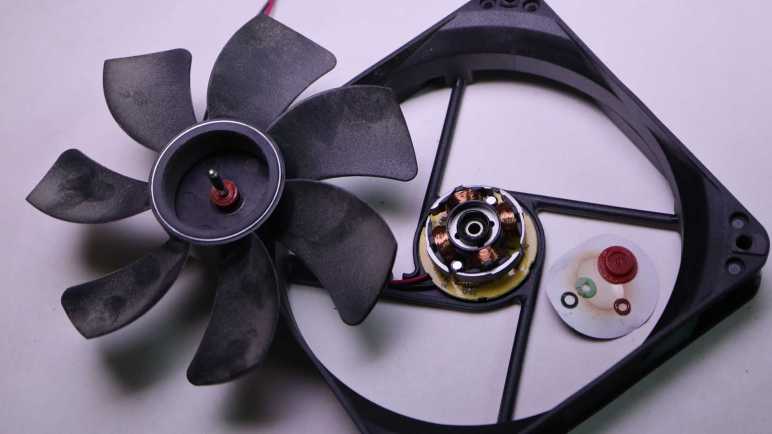
Popping off the white plastic split ring allowed the fan to come apart. I saw no visible wear to explain the noise this fan had been generating. At some point in the future I hope to have the knowledge to know what to look for, which may require magnification equipment.
A closer view of the core of the fan. It is securely fastened to the plastic base.
I found no fasteners or clips to release, so I went with brute force: using large pliers to rip the core off the base to see the back of the circuit board.
The other fan was functionally fine until I accidentally broke a fan blade. It was made by Poweryear and they have no fault for this. It was entirely my clumsiness.
Under the label was a hard plastic seal. I was surprised to see this, it meant I could not access the plastic split ring (or functional equivalent) to disassemble the fan.
I went straight to ripping the core assembly off the chassis, unintentionally breaking another fan blade in the process. I still couldn’t get to the back side of this fan’s axle. Teardown foiled!
No matter, sleeve bearings fail and I’m sure I’ll have more dead 120mm cooling fans in the future. For now I can harvest my first 140mm fan from a misbehaving power supply.
While I think over what I might do with parts salvaged from a retired and disassembled Sonicare electric toothbrush, I played with its corresponding charging base.
Since both the toothbrush and the charging base are designed to sit on our bathroom sinks, they are both waterproof and have no exposed electrical contacts: charging is done inductively.
It doesn’t transmit very much power, based on the label claim that it only draws up to 1.4W.
After prying off that bottom panel with the information label, I see a solid mass of potting compound putting a quick end to this particular teardown session. What else can I do with this thing?
The oscilloscope reads a ~85kHz sine wave with an amplitude of ~40V peak-to-peak. I played with coil position and was surprised to learn being slightly off-center hardly affected transmitted power.
Removing the alignment post allowed me to go beyond the narrow range of axis alignment, where I confirmed the expected behavior: going too far decreased voltage transmitted. Inside the snapped-off alignment post was filled with a mystery black material. It is a brittle material that does not appear to be electrically conductive. A magnet is attracted to the broken-off post but I can’t tell if that’s necessarily this black stuff or perhaps there’s a piece of steel embedded further inside.
I found some electrical connectors and tested to verify they mate with the microwave motor coil terminals. Unfortunately, these terminals were dependent on the now-absent external enclosure for strength. When I pulled on my connector, the whole terminal came out breaking the wire.
And unfortunately, out of two wires I could have broken, I broke the inside wire. If I had broken the outside wire, it would have been pretty trivial to unwind a single loop to get some extra wire and solder it back on the terminal. But I broke the wire that’s buried underneath the entire coil, making this impractical to repair.
I started pulling on wire just for the sake of seeing what it’s like. This is extremely thin copper wire and there’s a lot of turns in this coil. I ended up with an impressively large hairball of fine copper wire.
It’s unfortunate I destroyed a salvaged coil that might have been fun for exploration. As fallback (or maybe they should have been the first option) I also have the Sonicare charging coils that were designed to work with this charging base. I kept it along with the bottom of the Sonicare enclosure to maintain precise alignment, though thanks to this experiment session I now know such alignment may not be strictly necessary.
I thought the fact it was a much smaller coil with far less wire would have meant I have a different voltage transformer. When sitting on the charging base, the oscilloscope reads about 34V peak-to-peak. I had expected more difference in voltage between the two coils.
Some knife work separated the coil assembly from the rest of the toothbrush chassis.
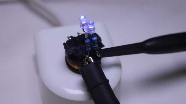
What’s the first step when exploring any electronic concept? Make it light some LEDs! Since this is an AC waveform, I soldered two salvaged LEDs side by side with opposite terminals.
When given DC power from my bench power supply, only one of the two LEDs would illuminate. If I reverse the polarity, the other LED would light up.
I didn’t bother with electrical connectors this time: the test LED assembly was soldered directly to coil terminals.
I put it on the charging base and both LEDs lit up, the expected response to AC power.
I connected my oscilloscope probes to see how the waveform changed with this load added to the system.
I can see a bump at roughly +/- 3.7V, the voltage drop point for these little blue LEDs.
That wraps a successful first test of using inductive power. Where might things go from here? If I can find the rectifiers I bought for the brushless motor generator experiment, I can get some amount of DC power flowing. It won’t be much power, a good chunk less than the 1.4W this charging base drew from the wall socket due to inductive power transmission losses. For comparison, slow USB charging is 5V @ 500mA or 2.5W, and that doesn’t even have to deal with inductive transmission losses. So any project idea would either have to be a modestly powered system or incorporate a battery like a Sonicare.
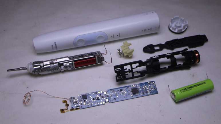
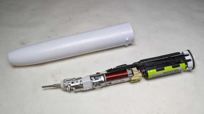
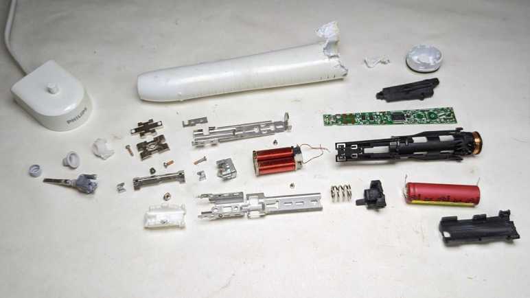
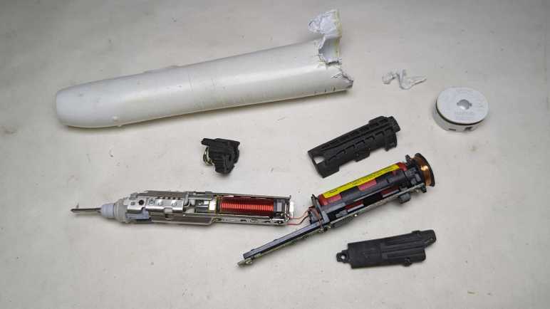
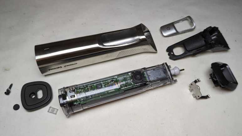
After looking over the electronics of my retired Philips Sonicare HX686P electric toothbrush, I unsoldered the main circuit board from the actuator, battery, and charging coil so I could remove it from the black plastic chassis.
Separating the main circuit board from the rest of the device also meant I could get good pictures both front and back.
I was surprised to see that there were a handful of surface-mounted components on the back. They couldn’t fit everything on one side.
The “pressing too hard” sensor’s flexible printed circuit strip is directly soldered to the back of the main board. I see ten soldering points, two per wire except for the left-most where four of them are connected to a single wire. This is consistent with power/ground/clock/data or some similar variation thereof.
On my previous Sonicare HX6530 teardown, my next step was taking the brush motor actuator apart. It was an instructive process, but a destructive one. Since the actuator in this HX686P is nearly identical, I doubt I’ll learn much from taking this one apart. It’s also in better shape, as it lacks the rust and deposits of water intrusion. I can keep it intact while hoping a project idea would arise. What would I do with it? I’m not sure! Recently, Hackaday featured somebody turning their old electric toothbrush into a tiny sander. The Hackaday writer Al Williams correctly pointed out this control board has a lot of features unsuitable to sanding. For example each session only runs for two minutes, with a small beep every 30 seconds. If we want to run it as a sander, we might be better off building our own control circuit for the actuator.
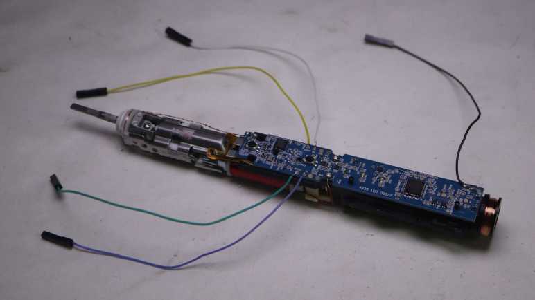
Sander or not, reusing the actuator will be best done with my own control circuit. I don’t know how to do that, but maybe this is a good opportunity to learn! I now have components on hand to support such a learning exploration: circuit boards with existing implementation, a disassembled actuator where I can test the coil by itself, and I have an intact actuator for potential application. And any knowledge I gain could continue to be useful in the future, because I’m still using a Sonicare every evening for my dental hygiene routine and it’s just a matter of time before I have additional retired toothbrushes to play with. Toothbrushes, and their associated charging bases.
I got inside my retired Philips Sonicare HX686P electric toothbrush and found a few physical signs of new features relative to my older Sonicare HX6530. Mechanically they seemed quite similar, but there’s a significant upgrade in electronics between the two.
Here’s the circuit board I pulled from the older HX6530, featuring a few surface-mounted components and even a few unpopulated positions, presumably to support features absent in this model.
And here is the newer HX686P circuit board. They are both the same length and have the same maximum width, but the older HX6530 board is a trapezoid that tapers versus a full rectangle in the newer HX686P. As a result the newer HX686P board has more surface area. It also has more surface mount components on board, packed more densely. There were no obvious unpopulated positions, but there’s at least one extraneous LED presumably to support feature absent in this model.
The ringleader of the new circus is a Cypress Semiconductor (since acquired by Infineon) CY8C4146AZI-S433, an ARM Cortex-M0+ microcontroller that offers a significant step up in computing power over a PIC16F726 used in the older HX6530.
The second largest chip on this board is a NXP MFRC630 for RFID applications. It makes sense it is positioned close to where the RFID antenna coil wires are soldered to the board.
Curious about what the chip is doing, I connected my oscilloscope to the RFID antenna wires where I could confirm… yep, something is happening. Beyond that, I don’t know what to look for or how to set my oscilloscope to be more informative.
Adjacent to the actuator electromagnet coil wires are these two tiny chips I inferred to be transistors controlling coil power. If so, they would be a counterpart to the Alpha & Omega Semiconductor field effect transistors found in the older HX6530 doing the same job yet only about a quarter of the size. Chip at position Q103 is marked 1Z W9n and chip at position Q104 is marked 1V W9n. There’s not enough room on these tiny chip to have full brand name and model number so this is an abbreviation. A web search on these designations turned up many results, but I couldn’t find anything relevant.
Adjacent to those are three white LEDs at position CR5, CR6, and CR7. Curiously, the external enclosure only had provision to show CR5 (“clean”) and CR6 (“white”) with only a smooth surface where CR7 would be. I never saw it illuminated, yet it was populated on this board during assembly.
The chip at position U2 is the third largest on this circuit board and has the abbreviation DEK 735. Another abbreviation I couldn’t find relevant information about.
The item at position F100 is in series with battery positive Vbat+ and labeled with just a single letter P. There is a very similar counterpart on the HX6530 board and I think they’re safety fuses. Perhaps P stands for polyfuse?
Near the charging coil (JC1 and JC2) and battery negative Vbat- are a pair of dual LEDs, each package contains a green and an orange LED side by side. These are used to indicate battery charging status (CR1) and notification for brush replacement (CR2).
It’s difficult to focus on the LED internals, here was my best effort.
And here’s the same item with the green LED illuminated. I want to get sharp pictures of these things, time will tell if that desire separates me from my money for a microscope camera.
I soldered wires to pads labeled SPDAT, SPCLK, Rx, and Tx so I could look at their activity under the oscilloscope. Rx stayed at the ground plane, while SPDAT, SPCLK, and Tx stayed at Vbat+ voltage level. I struck out again here, Sonicare firmware engineers are clearly not in the habit of shipping chatty hardware.
And finally, here’s a closeup shot of the chip I hypothesized was a brush actuator feedback sensor, sitting as it was over the gap between the electromagnet and permanent magnet. Perhaps it is a Hall effect sensor? Accelerometer? Audio microphone? There are many possible ways to measure actuator behavior, but again I struck out here. A search on its markings C180 1371G returned a lot of search results on Cessna 180 airplanes and Mercedes-Benz C-class automobiles, burying any information that might be relevant to a Sonicare toothbrush.
That’s what I’ve learned from poking around a disassembled Sonicare HX686P. What’s next?
I retired & took apart my Philips Sonicare HX6530 after it had slowly degraded over years. So slowly I didn’t realize until I was reminded by a newer unit: “Hey, this is what a Sonicare clean should feel like!”
I replaced it with this HX686P, which has also been recently retired due to degradation. But this one degraded overnight instead of gradually. Literally: one evening it felt fine, the next night “hey, what’s wrong with this thing?” My first thought was that I had accidentally triggered the “Easy-Start” feature, which introduced newcomers to Sonicare clean by starting easy and ramping up strength over time. I verified Easy-Start was not active, and ran out of ideas on why it might have suddenly weakened. Oh well, time for a new one and tearing down this one.
The manual for this HX686P explicitly stated it can be disassembled for battery disposal so I tried pushing on the metal toothbrush stem. Unlike attempts with the HX6530, I was successful popping this core loose. In addition to seeing if I can find any obvious signs of why it failed, I’ll be looking for physical implementation of some new features:
It works with newer brush heads to keep a usage count and notifying me when it’s time to replace the brush.
It detects when we’re pushing too hard for effective brushing, telling us to back off.
Comparing HX686P and HX6530 side by side, the mechanical components appear nearly identical.
There’s a loop of fiber-reinforced tape that would be useless for holding the metal assembly in place. I think it exists to hold the RFID antenna wire.
Peeling off the tape confirms there isn’t anything else underneath other than the RFID antenna wire. It also confirms the clips + welded system is still here. When I saw the welds on the old HX6530 I had wondered if it was a hack on top of an original clip-based design. Since it’s still here after several generations, I assume clips+weld is a belt-and-suspenders system to hold the mechanical actuator chassis together.
Here’s the other end of the RFID counter system, at the base of the brush head.
It was glued in place and impossible to remove non-destrutively, so I destroyed an old brush head for a closer look. The small chip is connected to a coil of wire that would sit aligned with the coil visible inside the toothbrush handle. I’ve read that people have tried to reverse-engineer this system.
Relative to the older Sonicare, another new component is this chip and capacitor sitting on a little segment of flexible printed circuit. Why are they here and what are they doing?
A hypothesis surfaced when looking at the side view: this chip is sitting above the gap between the electromagnet and permanent magnet, ideally placed to sense brush actuator lever motion. I think this is a sensor that feeds into the “is the user pushing too hard on the brush?” feature. To test this hypothesis, I peeled off the sensor which was held by double-sided tape. Once it was bent away, the “pushing too hard” alarm feature stopped working.
Another observation: The gap is noticeably larger here on the HX686P than on the older HX6530, but I’m not sure if that signified anything. On the other hand, the lack of water intrusion is certainly a good thing.
Until I decide to start destructively cut things away, I could only lift the circuit board a tiny bit. Peeking underneath, I don’t see any signs of a connector for the flexible board implying it’s soldered directly to the bottom of the circuit board. Before I try to get a better look at the bottom, there are plenty of interesting things up top.
After looking over the circuit board and charging coil of my retired Sonicare (HX6530) electric toothbrush, only the electromechanical actuator assembly remains. Earlier in this teardown I noticed a few welds, that’ll have to be dealt with at some point, but I’ll start with the screws at the base of the electromagnet.
There were two of them, one top and one bottom. Removing the first one was undramatic. As soon as I loosened the second, though, there was a metallic “click” and it took me a few seconds to figure out what happened: as soon as the screws were loose, the electromagnet core slid up against the permanent magnet.
Manually prying them apart, I see the gap adjustment ranges from a maximum of almost two millimeters down to no gap which was where it went when the screws were loosened. This distance would affect toothbrush performance but I don’t know in what ways, so I have no idea how to optimize this gap.
Here’s a picture taken earlier intended to show rust as sign of water intrusion, but here we can also see the original spacing between permanent magnet and electromagnet. That is a tiny gap and I doubt I could restore that precise distance again. Then again, perhaps this distance is wrong: maybe its gradual degradation of performance was due to the electromagnet slowly sliding towards the permanent magnet over many years? Ignorant of metrics to measure proper operation, I have no way to tell.
On the other end of the actuator, I could access a single screw. Loosening it freed the toothbrush stem assembly, caked with deposit left from water that got past the rubber seal.
Everything else was enclosed inside the stamped sheet metal shell held with stamped clips as well as spot welds. I’m curious if it was originally designed to be held with just the clips. The welds may have been added to the manufacturing process later when they realized the clips along weren’t strong enough, or maybe the welds were part of the plan all along.
A cutting wheel removed the welds, but the stamped clips were pretty strong even without them. I ended up cutting off one set of clips as well.
Once the top and bottom stamped sheet metal bits could be separated, I could extract the electromagnet and the pivoting lever sub-assembly.
Unscrewing the visible fastener freed the permanent magnet from the pivoting lever sub-assembly. The final fastener was hidden under the top plate of the pivoting lever sub-assembly, holding it together. Once undone, everything could come apart.
This was a lot more complex than I had expected. Once I saw this device worked by using an electromagnet to actuate a lever, I expected an one-piece arm with a magnet on one side and the toothbrush head on the other. I infer this complexity was required because they wanted to implement a very specific motion profile for optimal dental hygiene. All these parts allow them to fine-tune the motion: from changing the thickness of spring steel plates to increasing/decreasing the mass at either end of the lever. If they wanted to optimize production costs, it wouldn’t need this much complexity to just vibrate a brush head. A cheaper and simpler knockoff could vibrate but not necessarily replicate the precise motion.
Would I notice the difference between a genuine Philips Sonicare and some cheap knockoff? Maybe yes, but maybe not alone by itself. I think I’ll notice a difference with a side-by-side comparison. After using Sonicare for years, I think I have a good idea of what feels right. While a slight gradual degradation may go unnoticed as was the case with this unit, if something goes wrong overnight I’ll notice. I’m confident because that happened with my next Sonicare.
After disassembling my retired Philips Sonicare (HX6530) enough to access its internal circuitry, I paused to take a look at it under my oscilloscope. After completing that detour, the oscilloscope probes were put away, and the mechanical tools came back out to resume disassembly.
First to be freed was the circuit board. In addition to a few plastic clips (and one melted plastic rivet) it was held with six soldered connections: Two wires for the actuator coil, two for the battery, and two for the charging coil.
From left to the right, here are the components I recognized on the board:
A single green surface-mount LED, the only user visual feedback on this device
A single button, the only user input.
Six large pads. There’s solder on Rx and Tx because I wanted to see if it was transmitting serial data. (It did not.) Two of the pads are labeled Gnd and they both electrically connected to ground. The remaining two pads are labeled Vdd and Vpp, and I don’t understand how they differ. They both seem to show the current battery voltage.
Two resistors R1 and R3, then the two Alpha & Omega field effect transistors Q1 and Q2.
Two more resistors R5 and R4, than the two pads leading to actuator coil.
A through-hole for the battery positive terminal, leading to F1 and an unoccupied pair of pads. The component sitting at F1 has a small “P” printed on it and it doesn’t look like a resistor. Thinking of electronic things that start with “F” and would make sense at the battery terminal, I think this is a safety fuse. The unoccupied pair of pads has a thin trace connecting them. I guess this is a provision to put something in line with battery power: we can cut that trace then solder something on those pads.
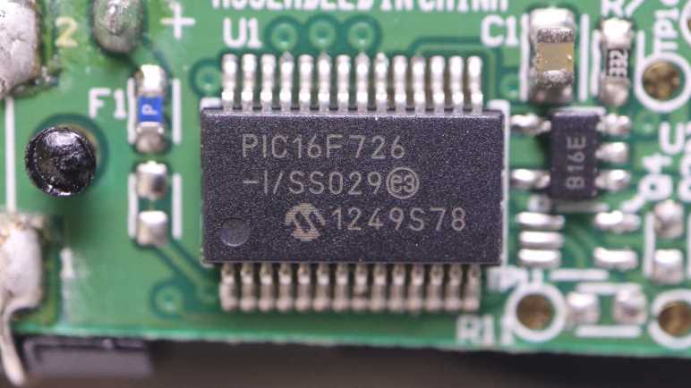
U1 is the Microchip PIC16F726 microcontroller.
I got lost after this point. There are many unpopulated pads, I presume features for higher end models. SW2 would be for another switch, but what might sit at BZ1? Some of these components would deal with power coming in from the charging coil (connected at the holes on either side of the CR6 lettering) and maybe for battery management. The positive battery terminal connection point was mentioned earlier, the negative terminal connects to the upper-right hole adjacent to lettering JP1.
Speaking of the battery, unsoldering its connection to the circuit board freed it from the chassis. Now we can read the lettering on its side telling us it is a 14500 form factor (14mm diameter, 50.0mm length) cylindrical cell with a capacity of 680mAh (milli-Amp hours).
The charging coil stayed on the black rigid plastic chassis, but now that it is freed from the circuit board I hooked it up to the oscilloscope again for another look.
Left plot was taken while the charging coil was connected to the circuit board, right plot is the coil by itself. Note the vertical scale has changed between these two plots: 1V/div on the left and 5V/div on the right. The most obvious difference is the shape: it is now a sine wave instead of a square wave. The amplitude is much larger at about 30V peak-to-peak or 15V above and below the center point. This is roughly triple the rectified 5V I saw earlier. I don’t know enough about analog electronics to know what would accomplish this on the now-removed circuit board, maybe in the future.
I’m partway through disassembling a retired Sonicare electric toothbrush, far enough to see all the internal components. The likelihood of irreversible damage rises sharply from this point. Before I do anything destructive, I wanted to check out some electrical characteristics under my oscilloscope.
The biggest chip on this circuit board is a Microchip PIC16F726 microcontroller.
Next largest are a pair of chips with the logo of Alpha & Omega Semiconductor. A brand I’ve encountered in a few previous teardowns as a provider of field-effect transistors. Their 8801 is a pair of P-channel FET and the 8808 is a pair of N-channel FET, sitting close to the actuator coil wires.
I didn’t see any other significant-looking chips on this board. I thought there might be a lithium-ion battery management chip like a 4056, but I found no likely candidates. Perhaps such tasks are handled in software running on that PIC16F726.
First target: big test pads labeled “Tx” and “Rx”. These names usually denotes serial communication and I was curious if there’d be any sort of diagnostic messages during runtime. I don’t know any of its parameters (voltage, baud rate, etc) so the first pass is to look at them under the oscilloscope. As a user, there were only a few events I can trigger: start/stop brushing, and start/stop charging. I was disappointed but not surprised to see no electrical activity on these pads. The chip is staying quiet until it sees the right access code, which I don’t have.
Second target: the inductive charging coil. Channels 3 and 4 were connected to either end of the coil and plotted relative to battery negative as ground. The plot on the left has both channels 3 and 4, the plot on the right has only channel 3.
I had expected to see a 60Hz sine wave on this coil when sitting on the charging base, which runs on household power ~120V AC @ 60Hz. What I saw had a period of around 11us, which translates to about 90 kilohertz. That was a surprise, as well as the amplitude. I had expected it to be symmetric about the ground plane but it’s actually going from about 0V to 5V. And finally, it is a square wave and not a sine wave. In short, I expected none of this and I don’t understand what I’m looking at.
I left the toothbrush on the charging base connected to the oscilloscope until the status LED went from blinking (“charging”) to steady on (“charge complete”). I measured the battery voltage at 4.1V at this point. I thought perhaps the inductive charging coil would look different when it’s not actively charging, but it looks pretty much the same.
Third target: the brush actuator coil driven by those Alpha & Omega FETs. Again channels 3 and 4 were connected to either end of the coil and plotted relative to battery negative. The plot on the left has both channels 3 and 4, the one on the right only has channel 3.
When actively brushing, the coil is activated in one direction (~5V on channel 3, 0V on channel 4.) for roughly 1.25ms. Then both ends are grounded for roughly 0.7ms. Then the coil is energized the other way (0V on channel 3, ~5V on channel 4) for roughly the same duration.
Every 30 seconds the brushing pauses and the toothbrush issues a “beep’ to remind us to switch to a different set of teeth. I had been curious if this was implemented as reduced voltage level or reduced coil energizing cycle. The answer is the latter: all of the time periods described above shortens by roughly 25%, that was enough to stop the coil from brushing but enough to cause an audible beep.
After watching the brush actuator waveform for a few cycles, the toothbrush fell silent and the waveform collapsed to a single phase. Oh no, what happened?
One of the coil wires had broken. It was designed to handle stress of brush vibration, but not with the additional weight of an oscilloscope probe. That was too much and metal fatigue took care of the rest. Well, I’ve seen what I wanted to see so this is a good place to stop my oscilloscope examination and resume mechanical disassembly.
After wrapping up a teardown (and unexpected repair) of a Philips product, I decided that was a good teardown theme and proceeded to another retired product from a different Philips subsidiary: Sonicare.
This Sonicare HX6530 could still vibrate the toothbrush head, but it could no longer clean effectively. Its degradation was long and gradual enough I didn’t notice until my dental hygienist commented on my worsening dental buildup. I tried a new Sonicare and realized I should have retired this HX6530 long ago.
Some of the newer Sonicare have been designed to be easily opened for battery recycling, we just have to push on the metal toothbrush stem. This older model is locked up tight and not so easily opened. I thought maybe clamping the plastic will flex and break some glue joints, but nothing interesting happened.
Using my also-much-degraded Wondercutter (a topic for another post) I cut an entry slot and started prying away with pliers. I quickly got far enough to confirm there’s a black rubber O-ring as water barrier.
More prying later, I reached a piece of black plastic that looked like a latch. Once all its surrounding plastic has been pried awayI tried pushing on the metal stem again.
Cutting one latch away weakened the holding power of the remaining latch, so this time a firm push on the metal stem was enough to push everything out of the enclosure.
There are definite signs of water intrusion inside, such as these dried deposits near the tip.
There was also rust near the interface between the coil and the armature. Unlike hair trimmers, reciprocating motion is not created here with a spinning motor shaft turning a crank. Instead it appears to be using a pair of coils facing a magnet.
I didn’t see an obvious candidate to explain why this toothbrush degraded. The signs of water intrusion didn’t seem sufficient to damage the electromechanical assembly, and all components appear intact on the circuit board. The battery voltage measured 3.8V DC, within nominal range.
I had expected the battery to be a single lithium ion cell in the commodity 18650 form factor. It turned out to be a much smaller cylindrical cell made by Sanyo. Here it is next to a 18650 cell for size comparison. Also visible to the left is the coil for interacting with the charging base.
I could peel three large pieces off the core. They are all made of soft vibration-absorbing material, the midships piece incorporated a spring for even more vibration absorption. It makes sense that keeping vibration under control would be an important mechanical engineering consideration for this device. It’s not just for user comfort, they have to make sure it doesn’t shake itself apart!
I was encouraged by the few Philips-head screws I could see at the base of the electromechanical assembly, thinking I might be able to disassemble it non-destructively.
That hope was dashed when I saw the other end of these two metal pieces were welded together. Oh well! Going further will be a destructive act. Before I do that, though, I want to probe the electrical aspects of this device.
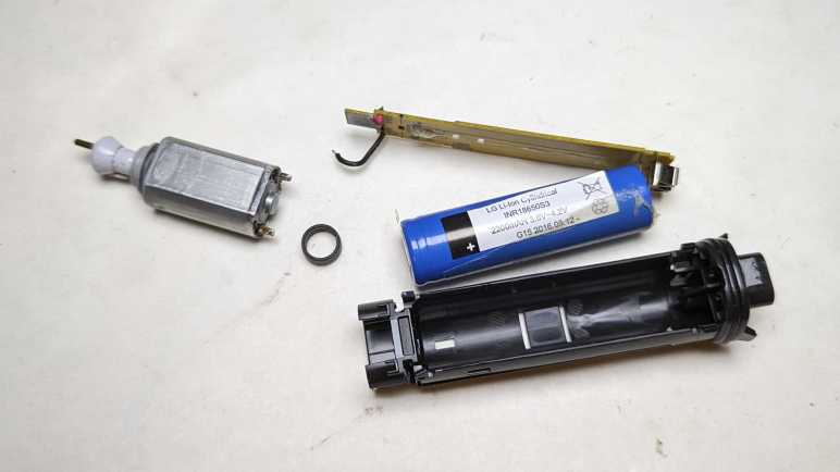
I’ve managed to disassemble the exterior components of a retired Philips Norelco Multigroom (MG7790) which made only a moderate mess with its hair fragments trapped within. In earlier hair clipper teardowns, that was enough for me to access all internal components. However, this unit is IPX7 waterproof which meant everything is inside a clear plastic watertight capsule.
The control circuitry is much more sophisticated than those in the two earlier hair clippers, though I’m not sure why. At the end of the day, this just needs to turn a motor on or off. Perhaps there’s battery management as well? The little of blue peeking through various gaps in this enclosure hints at a single lithium-ion battery in a commodity 18650 cylindrical cell form factor.
The motor is genuine Mabuchi! A pioneering giant for small DC motors, I usually encounter knockoffs of popular Mabuchi designs instead of a genuine Mabuchi. Either that, or it’s a counterfeiter brazen enough to print the Mabuchi logo on their wares. I’d like to think Philips/Norelco uses the real thing.
The bottom of the clear plastic capsule is sealed with a black plastic plug at the bottom, held in place with four beefy clips. I had hoped to release those clips peacefully, but I shattered some of the clear plastic. The cracks extended past the watertight O-rings, meaning I’ve managed to destroy its waterproof worthiness.
Not much to lose now! Feeling liberated because I don’t have to worry about preserving its watertight seals, I tore apart the retaining mechanism. This clear plastic was interesting: most of it is tough and ductile under stress like a polycarbonate, except infrequent times where it shatters like brittle acrylic. I wish I knew more plastic engineering to better understand this material’s behavior.
I thought the black plastic plug at the end was a separate piece of plastic from the structural chassis for all internal components. It turns out to be a single piece, so everything slid out together.
The chip that seems to be in charge is stamped with 10368A F15 H3G7A. A web search found a likely candidate in the Renesas RL78/G12 family of microcontrollers. The R5F10368 variation has 8KB of code flash, no onboard data flash, 768 bytes of RAM. It comes in a 20-pin TSSOP package which matches what’s on this board.
If I’ve correctly identified the controller, it means this is a very software-centric minimalist application because this MCU lacks onboard peripherals befitting the hardware. (Comparison: the MCU in this smoke detector is optimized to be a turnkey smoke detector solution.) There’s no obvious motor control peripheral like hardware PWM, though perhaps an offboard MOSFET would suffice as it only needs to turn the motor on/off. There’s no explicit lithium-ion battery management capability like a 4056 chip, but there is an A/D converter that would be suitable for monitoring battery voltage.
Speaking of the battery, separating the circuit board from the chassis exposed the battery. The label says:
LG Li-Ion Cylindrical
INR18650S3
2200mAH 3.6V~4.2V
G15 2016.08.12
I retired this trimmer because the motor would stop in the middle of a session, even when fully charged, so I decided the battery has degraded. I thought it might be fun to replace the battery cell and see if that gets it back up and running, hence the concern about trying to preserve the watertight barrier. But as it turned out, I had misdiagnosed the problem.
After my Remington hair clipper‘s batteries failed, I had to shop for a replacement. Costco had the Philips Norelco Multigroom (MG7790) on sale and I thought I’d give it a shot. Rather than a single wide fixed-size cutting blade, the Multigroom came with multiple cutting elements to serve different hair cutting/trimming purposes. The tradeoff for this versatility is that the widest flat cutting element is around 2/3 the width of the Remington hair clipper blade. Part of being a smaller and lighter weight device, which I learned to appreciate during its few years of use. I didn’t end up using the other cutting elements very much, and the narrower width wasn’t a significant detriment in my usage pattern.
After a few years of use, the motor would stop running in the middle of a session even if I fully charge the battery immediately beforehand. The manual claimed a fully charged battery can deliver up to six hours of use, but I couldn’t even get ten minutes! I bought a replacement and placed this unit in the teardown waiting list alongside the Conair and Remington hair clippers, where they waited until now.
The two old hair clippers both had a sticker telling us to properly recycle their nickel-cadmium batteries within. There was no such label here telling us of the type of rechargeable batteries used. The power adapter operates at 15V DC, far above the voltage range of any battery pack I would expect to see within. This implies a voltage buck converter in the charging circuit, a level of sophistication I associate with lithium chemistry battery management systems.
An important detail for teardown purposes is at the bottom of multigroom label: “IPX7” followed by a faucet icon. This device is waterproof enough to be rinsed clean under running water and can tolerate being briefly submerged in water if we accidentally drop it in the tub. Waterproofing makes teardowns difficult because the interior may be glued shut and/or buried under epoxy resin. Even if they weren’t, a teardown may irreversibly damage the water barrier.
The AC adapter uses this vaguely B-shaped plug that I haven’t seen anywhere else, possibly proprietary to Philips/Norelco. Next to the charging port at the base is a Torx-headed screw hidden under a rubber cover. That looks like a good place to start.
The base plate came free easily. Loose fit and no seals meant the waterproof barrier must be further within. Disappointingly, nothing else budged after this plate was removed, so I started looking at the other end.
Different cutting elements can be easily snapped on and off the top. When removed, we can see the motor-driven crank. The manually aptly referred to this as the hair chamber. It’s easy to dump out loose hair, but the many small corners meant it takes a lot of work to clear out every little piece. Going in with a cotton swab, I got enough of the corners cleared out to see three small fasteners (combination Torx and flat head) buried underneath.
Releasing those three small self-tapping plastic screws allowed hair chamber disassembly, releasing a lot of trapped hair along the way. Now the guts of the device can slide back and forth around 3-5mm, but not quite freed yet.
The last piece of the interlocking puzzle was the power button, which was held by multiple clips that also served as tabs holding multiple internal elements together. I damaged one clip removing it.
The internals slid out as a single piece enclosed in clear plastic. The motor pokes out the top, a rubber dome on the side pushes on the power switch, and a plug of dark gray plastic sealed the bottom. Numerous rubber O-rings made it clear this was the water barrier. Getting inside non-destructively proved to be a challenge.
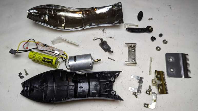
I used my Conair HC318R hair clipper for several years. Until its batteries couldn’t hold enough charge to last a single cutting session, at which point the blades were pretty worn as well. It was replaced by a Remington HC-920 which was itself retired after several years of service. Tearing down a retired hair clipper will scatter tiny bits of hair all over my workbench, so I’m working through my backlog of three retired clippers all at once.
I picked up the first major difference from the product label: the Conair listed 4.5V but this Remington only lists its voltage at 3V. This implies two nickel-cadmium battery cells in series instead of three as in the Conair. Theoretically it meant the Remington was less powerful, but if so, the difference wasn’t enough for me to notice. This may be because I didn’t have a fair back-to-back comparison. I would have been comparing the Conair with worn-out blades and batteries against a new Remington.
Both clippers had two prominent Philips-head screws on the cutting head, allowing easy removal of the outer fixed blade less-easy removal of the inner moving blade. This allows us to clean out hair that may have accumulated between the two blades or against the motor-driven crank seen here. This Remington used machine screws threaded into a piece of metal, which should be more durable and longer-lasting than Conair’s approach of using screws that self-tap into plastic. In practice, the longevity was not a problem, though that may be more a commentary on my cleaning frequency (not very) than on mechanical design.
There were two less-prominent screws holding the thing together. One at the base of the handle, and one in the length-adjustment lever. They were recessed but otherwise exposed on the Conair, the Remington added cosmetic covers over them for better aesthetics. Once removed, a metal bracket at the front (what the cutting head machine screws held into) could be slid off, then we can open the enclosure.
Unlike the Conair, Remington has this additional metal strap to hold the motor in place. There’s a piece of foam between the strap and the motor to dampen vibration. The strap are held by a pair of Philips-head screws which had this orange material on top. It may just be a thread locking mechanism, but having orange stuff in the fastener head made things more difficult to remove.
As inferred by the 3V DC listed outside, there is a pair of Sanyo-made AA-sized nickel cadmium battery cells inside.
As I lifted the innards, I could see some external signs of failure on this battery cell. Not sure if this is corrosion from leaking chemicals or something else, all I know is I should avoid touching it.
The Remington circuit board is even simpler than Conair’s board, showing a slightly different evolution. Here R1 was deemed unnecessary and replaced with a solder bridge.
All disassembled components will meet fates similar to their Conair counterparts. Metal will be recycled, plastic will go into landfill. The battery will be added to a collection of nickel-cadmium batteries that will be turned in for responsible disposal. The charging barrel jack will stay with the AC adapter for potential reuse.
I started removing this shiny brass metal crank from the motor output shaft but changed my mind. First, unlike the Conair motor mount + crank, it didn’t trap much hair and could be cleaned up. Second, it was fastened very tightly and would be a lot of effort to remove. Third, I might want to build a reciprocating motion device at some point, and it’d be handy to have this motor already set up ready to go. Fourth, it looks really nice I wouldn’t know what else to do with it anyway.
And finally, there’s no rush. I already have a nearly identical motor salvaged from the Conair unit, with the plastic crank already removed. I’ll worry about removing that piece of brass onceI have an actual need to do so. Right now, I have a third hair clipper to take apart.
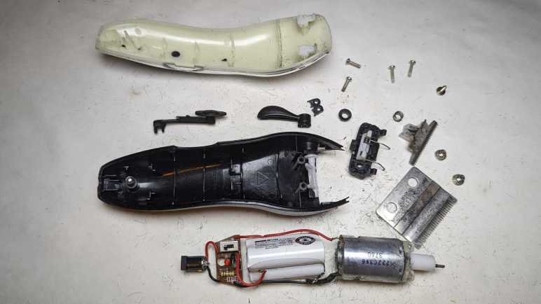
I have a set of retired hair clippers on the teardown to-do list. My hair are like bristles in a stiff wire brush, and wears down cutting blades quickly, fresh clippers only keep their “oh wow, this cuts nice” feeling for the first half-dozen or so sessions. I use one for a few years until its rechargeable battery degrades. By that point, its blades are dulled enough to be tugging and pulling hair while cutting. Between the battery and the blade, it was time for a new one.
I’ve been avoiding these teardowns because I knew it would get messy, given the short fragments of hair clinging to every surface of these clippers via either lubrication oil or static electricity. I knew I will find small pieces of hair everywhere for weeks after each teardown. But the paper liner on my workbench is starting to get dirty enough for replacement, and I saw an opportunity: I can do these messy teardowns and throw away the liner, hopefully easing cleanup.
First up is the Conair HC318R. Information embossed on the back of the device was hard to photograph, but it says:
(C) CONAIR CORPORATION, EAST WINDSOR
NJ 08520 / GLENDALE, AZ 85307
MODEL HC318R 4.5V DC 1000mA
USE WITH ADAPTER CA12
MADE IN CHINA
HOTLINE 1-800-3-CONAIR
Next to this information is a small tag informing me the device contains nickel-cadmium battery and must be recycled or disposed of properly. I expect to find three cells wired in series given the 4.5V DC written on the device.
If somebody has the clipper but not the charger, here are the specifications on its label. The charging port looks to be a pretty standard barrel jack wired to be center-positive.
There were two very large and easily accessible Philips-head screws on the blade. Removing them frees the outer blade, allowing us to clean inside.
The inner blade lifts away to expose the motor-driven crank.
Opening the enclosure allows a look inside.
Behind the motor sat the expected three-cell nickel-cadmium battery pack, each cell is the size of an AA battery.
There were no further fasteners holding the working bits in place. Once the enclosure was opened, the electrical guts are easily lifted out.
The battery pack manufacturer is BYD, the battery company that grew into an automotive manufacturing conglomerate. I measured less than 2V across its terminals, so it’s either severely discharged or there’s a dead cell in the pack. Neither would be a surprise after years of use followed by more years of waiting for teardown.
Thanks to decades of manufacturing at scale, nickel-cadmium batteries are cheap. They are also hardy and tolerant of abuse, which cut costs further because they don’t need sophisticated battery management electronics like lithium-based batteries do. Here we have just a small single-layer circuit board housing the power switch, two resistors, two diodes, and one light-emitting diode. M+ (motor positive) is connected to one side of the switch opposite B+ (battery positive). M- location was unused: it had a short trace to diode D3 which was also absent. Motor negative was wired to battery negative off board then a single wire led to B- on this board, which was electrically connected to the other end of the absent diode D3. Apparently, they decided D3 was unnecessary! Finally, L+/L- lead to the AC adapter barrel jack for charging.
The motor is marked with 222C3V6 3760 but I didn’t find much from that information. The crank is a piece of friction-fit plastic and slid off unexpectedly easily. The motor mount was installed with two small Philips-head screws and easily removed.
The barrel jack will stay with the AC adapter for possible future reuse. The motor will join many other salvaged motors. The battery pack will go in the nickel-cadmium battery recycle bag. The circuit board will go into the electronic recycle box. Metal blade and fasteners will go into metal recycle bin. Remaining plastic enclosure bits will go into landfill along with many bits of hair. I didn’t put too much effort into cleaning the workbench, because I had more hair clippers for teardown.
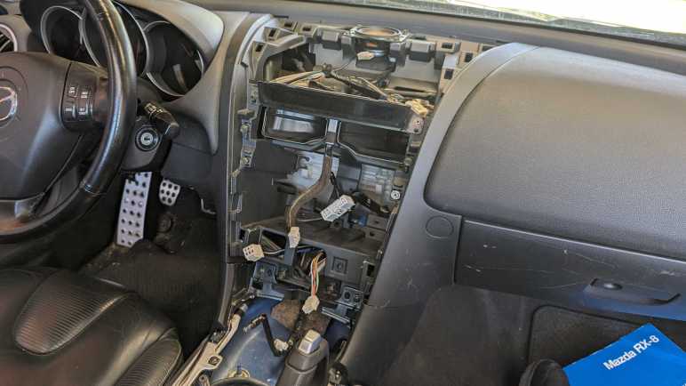
After reviewing RX-8 owner forums, I feel I have a good idea how to tackle my project: swap out my 2004 Mazda RX-8’s factory navigation system LCD screen for a modern wireless CarPlay/Android Auto receiver. The first order of business is to extract that existing factory navigation LCD assembly, which required taking apart many pieces of interior trim. Such extensive disassembly was needed because Mazda designed the center console as a series of overlapping pieces. Each one had to be removed to uncover fasteners for the next one.
The first step was easy: unscrew my manual transmission shift knob. (I have no idea what this looks like for RX-8 with automatic transmission.)
Upper console panel surrounding the shifter is held only by clips, so it can be loosened by careful prying. No screwdriver necessary. Once loosened, I unplugged three electrical connectors: the navigation control panel, and seat warmer switches for driver’s side and passenger side seats.
A salute to the Mazda engineers who put in extra effort to make it extremely difficult to mix up the driver-side and passenger-side seat warmer controls. Not only are they differentiated by color (black for driver’s side and white for passenger side) they are also physically keyed differently. The driver’s side had two shallow channels, the passenger side had one deep channel and one blocked channel.
Now we can access the two screws holding the ashtray panel in place.
There are three electrical connections to the ashtray panel. One for the cigarette lighter socket, one to illuminate that socket, and one to illuminate the tray. I could not extract the tray illumination assembly, but I eventually figured out it was much easier to remove the bulb.
With the ashtray panel out of the way, we can access two screws holding the center panel (with audio and HVAC controls) in place.
Before we can slide the audio head unit + HVAC controls module out, we have to take a side detour to the driver’s side footwell. Just under the steering column is a plastic panel held by clips, and behind it a metal bracket held by these four screws.
Then we can stick our head down there. Looking towards the center console, we can see a single 10mm bolt in the side of the audio head unit that must be removed. Don’t get distracted by the two nuts. Theyare much more easily accessible but will not help with this task.
Once that bolt is removed, I pulled on the panel to release four clips at these marked locations. Because this panel is glossy black, I was wary about using prying tools and didn’t use them. This was a mistake: in order to loosen the top two clips, I pulled too hard on the glossy panel and damaged it. (Though I wouldn’t realize it until later.)
Once loosened, I reached my hand behind this panel to unplug all the electrical connectors. From top to bottom:
Connector to the LED status screen.
Small round AM/FM antenna connector.
Large rectangular connector for power, speakers, etc.
Beefy connector directly behind the fan speed knob, presumably for fan motor.
Smaller connector, presumably for remainder of HVAC controls.
After extracting the audio/HVAC panel, I could access two screws holding the center ventilator grille.
Once that’s removed, I could finally access the two screws holding the navigation LCD unit panel.
Beyond those two screws, the panel is held by copious clips all around. Loosening them allowed access to unplug three electrical connectors from the navigation LCD unit:
Beefy grounding cable
Power and communication with the navigation computer between the rear seats.
Center console control panel that sat just behind the shifter.
The navigation LCD assembly is now freed.
A view of the cavity formerly hosting said assembly. This view also shows location for all the clips.
Someone more familiar with this system might be able to remove the navigation LCD panel without fully disassembling everything as I did. For example, in hindsight the shifter surround panel could probably move enough to allow access to ashtray panel screws without disconnecting seat warmer and navigation control panel connectors. But I didn’t know that at the time, and I was curious to see what’s behind these panels.
Next, the newly freed navigation LCD assembly is moved to a more comfortable work area for further disassembly.
My last teardown got really messy, but that was because I didn’t figure out how to do it right (nondestructively) until the day afterwards. Since I have all of my mess cleanup tools already set up, I decided to tackle projects I had been postponing because I knew they would be messy.
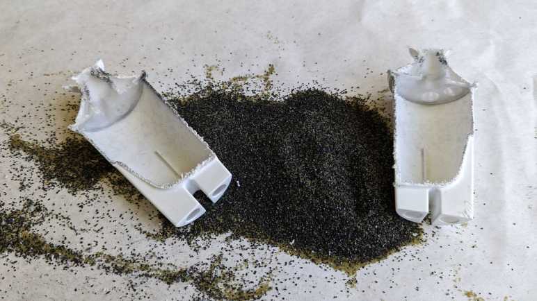
A Brita water filter cartridge is a consumable item to be replaced at regular intervals. From the Wikipedia page for Brita I learned the cartridge contents mostly consisted of “activated carbon” and “ion-exchange resin”.
Some years back, Brita evolved their cartridges to have this inverted-cone shape at the top. This serves as a convenient handle for handling the filter during replacement, but I also understood it had the purpose of diverting the force of water. This filter needs time to do its job, and it is counterproductive to have a stream of tap water force their way directly into the filter. This diverter sends that force sideways.
Given this externally visible mechanism, I started wondering about whether there were any internal mechanisms out of sight. Is this filter just a simple container or are there clever internal baffles to optimize filtering capability? I was also curious if I could see any visible signs of a used filter. I live in an area with hard water where everything that touches water inevitably builds up hard scales. Would I see similar buildup inside a used filter?
When this filter was replaced, I set it aside to dry. I hope it would make things easier to handle and drying would increase the odds of seeing any hard water buildup that might be visible. Once dried, I took a saw and cut it in half. I got the big mess I expected.
This is a closeup of the fine mesh keeping the filter particles out of my drinking water. This is the top mesh, molded from a slightly different textured plastic. There’s also a counterpart bottom mesh. Other than these meshes, there are no internal structures of note inside the filter.
Matching Wikipedia description, I see two different types of material within. I would guess the angular black pieces are activated carbon, and the round translucent yellow-green balls are the ion-exchange resin. And unfortunately, because the action of sawing the cartridge in half created a lot of sawdust from the enclosure’s white plastic, it was not possible to distinguish anything that might be hard water deposit on the filter material.
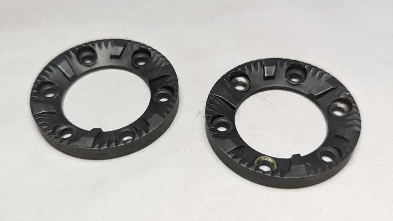
I took apart a retired burr-type coffee grinder and had a hard time because I couldn’t figure out how to take it apart nondestructively. After everything was taken apart, I still was puzzled. While I thought over that problem, I took a closer look at the grinding burrs salvaged from the machine.
I had expected the static burr to be different from the rotating burr, but they appear to be identical parts. Once cleaned up, the only difference was damage visible on the rotating burr. It had been held by rivets that I drilled out and the drill bit scraped off some material. I suppose any optimization for better static vs. rotor performance wouldn’t have been worth the cost of having a different part to manufacturer.
They show minor wear after a few years of use, not nearly as much as I had expected. This material is quite tough standing up to the abuse of grinding coffee beans, far beyond what I can reasonably expect to 3D print. However, I am confident I could design and 3D print some other mechanism to reuse these grinding wheels. I’ll put them in the bin of interesting salvaged parts.
Back to the mystery of the grinder motor: while putting the motor away with other salvaged motors, I noticed strong similarity between the burr grinder motor (right) and the Bodnum chopper grinder motor (left). Their bodies have slightly different diameters and lengths, but show very similar construction techniques. The output shaft and mounting also look very similar.
Once I removed the mounting hardware, the two motors output ends are nearly identical. The only difference I can see is the Bodum motor (left) has a slightly longer threaded length.
With that interesting comparison, I turned both motors around. The motor shaft on the left had a slot so I can use a flat-blade screwdriver to keep the shaft from turning while I unscrew the chopping blade. There was no such visible slot on the right side motor, and that contributed to how my teardown became destructive. For the left side motor, I kept the two screws that mounted the motor to the base. The right side motor had two similar looking screws in identical positions. When I was going around removing every fastener I can find, I somehow overlooked this pair.
Removing all the tail end hardware showed an equally close resemblance between the two motors. While there is no flat slot for a screwdriver, the exposed shaft does have slightly flattened sides so I could grab them with an adjustable wrench. This would have allowed me to keep the motor shaft from rotating as I unscrewed the grinding burr and, from there, take the burr grinder apart nondestructively. This would have been good to find out earlier, now it is too late for the dismembered grinder. I’ll try to keep this lesson in mind for future teardowns.
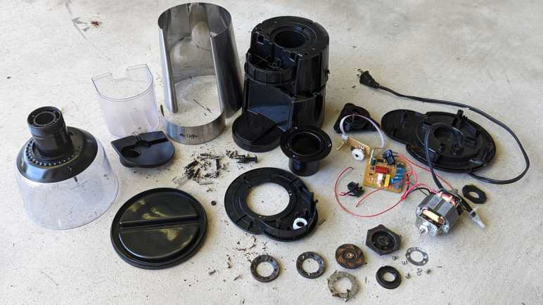
A spinning blade chopping type coffee grinder is a simple concept and can be built very affordably. As a contrast, here’s a more complex and sophisticated burr-type grinder by Mr. Coffee, model BVMC-BMH23.
Instead of a blade swirling through a small amount of beans, a burr-type grinder passes beans between two grinding surfaces. (burrs) This results in a wider adjustable range of grind coarseness and deliver more consistent results. The tradeoff is a more complicated process and that means a more expensive machine.
Hand-cranked coffee grinders are burr style grinders, because a human hand can’t twirl a spinning blade fast enough to chop coffee beans. From that history, one might expect burr-style grinders to work more slowly and quietly, but that expectation was definitely not true of this particular grinder. It is loud. REALLY loud. The previous owner thought it was ridiculous they needed to wear hearing protection to grind their coffee, so when they moved to a different city this machine was left for my teardown pile.
The input hopper is threaded into the machine body. Unscrewing it shows the two burrs covered in dust from all the coffee they’ve ground. Coarseness is dictated by distance between these two grinding surfaces, adjustable via how tightly the intake hopper is screwed into the body.
The nonmoving burr attached to the bottom of the input hopper is held by three screws and comes free easily. I couldn’t take the input hopper any further apart, I believe its plastic components are glued together.
After coffee beans are ground down between the two burrs, resulting bits are ejected out a rectangular port into the output bin.
A simple but effect power cord reel helps keep things neat. There are also five soft silicone feet arrayed around the bottom, each hiding a fastener. The following product information is also stamped on the bottom:
MR.COFFEE
BOCA RATION, FL33431
Coffee Grinder
Model:BVMC-BMH23
120Vac 60Hz 160W
Made in China. Fabrique en Chine
UL LISTED 2358 E130096
After removing the bottom panel, I was surprised to see electrical power wires transitioned from a thick durable household appliance cord to far thinner wires. The neutral wire went to the control circuit board.
The live wire snaked through the device to two safety switches.
One ensures the intake hopper is in place.
The other ensures the output bin is installed.
Removing the three most obvious screws freed the bottom part of the motor mount, but the motor itself is still quite solidly attached. I didn’t see what else is holding it in and the bottom of the motor shaft is not exposed, either. I removed every other fastener I could access from here, but that didn’t release anything.
I had to come back to the top and remove three screws holding this input funnel.
Then the top panel could be freed.
Once the top panel is removed, we can slide off two sheets of metal veneer disguising the plastic nature of this beast.
Top panel controls consisted of a button to start and stop the motor. Surrounding the button is a knob the user could turn to indicate how long to run the motor before it shuts off automatically.
I had expected some sort of integrated button-and-potentiometer unit underneath, like those I found on a car audio head unit to control power & volume. But here is actually a mechanical contraption with separate button and a potentiometer. The control knob is directly over the button for a straightforward connection, but the potentiometer is offset and needed a pair of gears to convey motion. The gear attached to the knob had two sets of “teeth”: one set is actual gear teeth with a sharp profile to convey motion to the potentiometer, the other has a softer rounder profile and that works with a small length of spring steel to give tactile “click” feedback of entirely arbitrary steps in the potentiometer.
This board also had an LED and two resistors. I believe one acts as a current-limiting resistor for the LED and the other a pull-up resistor for the button.
That four-conductor wire leads to the main control board, which had four more connectors: Motor +/- and AC electric power live/neutral.
And… I’m stuck. I saw no more fasteners I could undo, nor do I see any likely hiding places for them. The motor is still securely fastened to the chassis. In the previous two coffee grinder teardowns, the back end of the motor shaft was exposed with a slot where I could insert a flat-blade screwdriver to keep the motor shaft from turning while I unscrewed the chopping blade. In contrast, the back end of this motor has a flat slot, but it’s not the motor shaft and it didn’t help me keep the shaft from turning.
Perhaps fasteners are hidden under this burr? But I don’t see fasteners, those three brass looking components look more like rivets.
I tried drilling them out and, yep, they’re rivets. Freeing the burr and a spinning blade of death beneath it.
But still no fasteners.
Well, this thing is made of plastic, and I know I can cut plastic. I sawed off half of the chassis so I can get a clear side look at the motor mount.
I see hints of four threaded fastneers, but no closer to gaining access to them.
I cut the entire assembly free from the base and still no closer to an answer.
After prying at the grinding wheel for a while, it finally came loose. It was screwed onto the shaft just as the cutting blade did for the earlier coffee grinders.
The motor is finally freed.
Even with the help of hindsight, I’m not sure how I could have disassembled this nondestructively. I would need a method to keep the motor shaft from turning while I unscrewed the grinding wheel. (Drilling out the rivets were an unnecessary detour.) But I still don’t see how I could have accomplished that.
I took apart another low-end coffee maker and it was much like the first one I took apart. This theme continues with the next teardown: Bodum’s coffee grinder model 11160-3.
At its core, it is a blade spun by an electric motor to chop coffee beans into smaller pieces. From that perspective it isn’t terribly different from the Hamilton Beach 80344 I took apart earlier. But there are small differences in execution and the Hamilton Beach seems to be the better thought-out device.
The first of many examples is their power cord management. The bottom of the Hamilton Beach grinder is a knob that we can turn to reel in the power cord into a clever and compact mechanism. This Bodum grinder just has a wind-it-yourself slot for power cable.
The silver product information tag displayed the following information:
designed by bodum in switzerland
Assembled in China
Model no. 11160-3
Voltage 120V~60Hz
Power 150W
CONFORMS TO UL STD. 982
CERTIFIED TO CSA STD. C22.2
No. 1335.1 & 1335.2.14
In addition to power cable management, the controls are different. The Hamilton Beach grinder had a small circuit board for adjusting coarseness of the ground by controlling motor power. This Bodum grinder is an on/off operation.
The Hamilton Beach grinder also had a discreetly hidden safety switch that requires the lid to be installed before the motor could spin up. This Bodum grinder has a single switch pulling double duty. To activate that switch to turn the motor, the lid must be placed on the device (safety measure) and the red button mounted on the lid must be pressed (user intention.) It’s a clever way to reduce parts count without compromising safety, but they got too smart for their own good. Being the lowest recessed point, it is easy for coffee grounds to get stuck in that space. And because the button is mounted on the lid, its position varies somewhat due to manufacturing tolerances. Meaning it is possible to place the lid securely on the device yet have a misaligned switch pin that would not work when pressed. Both scenarios frustrate someone who just got out of bed and is trying to get their morning coffee. This grinder’s previous owner had one such morning too many and banished this grinder to my teardown pile.
Unspooling the power cable unveiled three easily accessible screws.
Removing that trio loosened the base, but that was only a partial disassembly. The blade is still installed on the shaft. With the grinding bowl still between them, a lot of parts are still stuck. I need to remove the blade, but I don’t see a way to hold the motor shaft still. The Hamilton Beach grinder motor had a simple slot cut in one end so a flat-blade screwdriver could keep the shaft from rotating. But the bottom end of this motor shaft is not yet accessible.
The answer is a pair of screws hidden under the power cable spooling mechanism. Once I removed the bottom panel (one of three clips did not survive the process) I could free the motor.
A-ha, there’s the motor shaft and the slot I needed to release the blade.
It is possible to disassemble the motor further, but I thought I’d keep it intact for now. Here’s a mostly disassembled chopping-type coffee grinder for contrast against a burr-type coffee grinder.
I’ve taken apart my retired phone VR headsets, so I’m moving on to retired appliances. This 5-cup coffee maker model number BVMC-SC05BL2-1 is the smallest and least expensive unit in Mr. Coffee product line. A direct counterpart to the Black & Decker DCM600B coffee maker I took apart earlier. I expect a machine with broadly similar implementation, as they’re both just need to make some coffee while being simple enough to be sold for under $20 USD.
This specific unit could still perform its core duty of making coffee but was retired due to failure of a convenience feature.
Here’s the coffee maker with its top open, showing the filtering tray. It is sitting under the hot water spout which pivots out of the way.
At the bottom of the filtering tray is a spring-loaded mechanism aligned to the top of the carafe.
When the carafe is present, it pushes the mechanism upwards allowing coffee to drip through. If we remove the carafe while coffee was still brewing, this valve is supposed to close. This will temporarily stop the coffee from dripping, allowing a cup to be poured before the brewing is done.
After years of use, the soft (silicone?) seal has degraded and could no longer stop the flow of coffee. This meant coffee kept dripping when that early cup is poured, making a huge mess on the hot plate. The only way to avoid that is to wait for all five cups to finish brewing before pouring some coffee, and that was deemed unacceptable by its owner and thus was retired and given to me for teardown.
Valve mechanism came apart easily. Now on to the rest of the machine.
I was surprised to find a tri-wing security screw here. The previous coffee maker teardown also saw a security fastener of a different type. I don’t know why both these companies felt simple basic bargain-priced machine justified security fastener protection.
Aside from those two screws, the bottom was held by plastic clips that could be undone. With the bottom removed, we can see some of that coffee that flowed past the worn valve and sizzled onto the hot plate has made it to the bottom of the machine. The following information was stamped on the bottom:
Mr. COffee
SUNBEAM PRODUCTS, INC.
BOCA RATON, FL 33431
Coffee Maker / Cafetiere
Model / Modele: BVMC-SC05BL2-1
650W 120VAC 60Hz
HOUSEHOLD USE ONLY
USAGE DOMESTIQUE SEULEMENT
DO NOT IMMERSE IN ANY LIQUID
N'IMMERGER DANS AUCUN LIQUIDE
Made in China / Fabrique en Chine

UL LISTED E236106
The entire electrical circuit of this machine. Power cable leads to a power switch, which leads to a heating element controlled by a thermal switch.
One novelty is the ball check valve. It was a separate component installed in the water tube on the Black & Decker machine. This machine molded the valve into the top half of the machine reducing parts count and assembly steps.
There were other minor differences, but I felt the molded-in check valve was the most novel. For the most part both machines were indeed nearly identical implementations of the same concept. I can say the same for the second coffee grinder I took apart.
There were many different variations on the Google Cardboard VR viewer concept. The Utopia 360 tried to fill out a long list of features but could not ultimately deliver. On the opposite end of the spectrum was View-Master VR. Functionally this headset is just a basic viewer, but well-implemented in sturdy plastic instead of cardboard. (Mattel has some expertise with making sturdy plastic toys, to put it mildly.) Like the rest of the Google Cardboard ecosystem, this product has been retired but its support page is still online for the moment.
This was my favorite headset for basic Google Cardboard experiences. Its phone holder mechanism worked well, and the screen-tapping mechanism was reliable. But its time has passed so it is teardown time.
There is no head strap with this headset: this was intended only for short handheld experiences just like the original View-Master was. Such intentions also meant there were no provisions for a USB power cable nor for headphone wires. No matter, I had cut my own slots for power and sound.
Removing four screws freed the phone holding mechanism.
A few more screws and it comes completely apart. I didn’t notice anything that made me say “A-ha, that’s why this holder worked so well!” The reasons must be more subtle or in details that I lack the knowledge to recognize.
A few more easily accessed screws freed the front panel.
Going further was a challenge. I removed all the fasteners I could access but nothing budged. I decided three important screws were hiding under plastic caps. Prying at them didn’t accomplish anything, they were either a precise friction fit or glued in place.
Taking the destructive route, I pulled out the drill. It turned out they weren’t just thin caps — they were long plugs that go all the way down to the screw. The tricky part is stopping the drill before it destroyed the Philips head because I need that to loosen the screw.
That process got a little messy, but it accomplished the objective.
After I cleaned up the mess, I could get a good look at the screen tapping mechanism. It translated the trademark up-down View-Master lever arm motion into a front-back screen tap. I was surprised there’s no pivot point for the fake lever arm motion. That path was purely dictated by a curved slot molded into orange plastic. This is a clever bit of mechanical design.
Electrically, there’s a wire connecting the black squishy screen-tapping nub and a small piece of black plastic in the middle of the lever. Both of these black plastic pieces had a small amount of electrical conductivity: my multimeter measured several thousand Ohms of resistance across a distance of 2-3 millimeters. Apparently, this is enough to conduct user finger to trigger capacitive touch screen. The rest of the plastic are electrical insulators or at least show up as open circuit in the multimeter.
Looking at this design, I wonder why the long black L-shaped arm isn’t made of the same marginally conductive plastic. Surely that would be cheaper than adding the parts and cost of that wire? Perhaps it is not conductive enough to trigger capacitive touch, or perhaps that material lacks mechanical strength required.
Removing the final few screws allowed the red main plastic body to separate from black soft plastic of the rear section. Plastic lenses were held between these two parts.
I’m sad I didn’t really learn anything from the phone holder as I have project ideas that would benefit from an effective phone holding mechanism. Seeing another implementation of capacitive touch is also informative, but I don’t know if I can turn any of it into applicable skill. Still, I had fun seeing how this sturdy viewer was put together and (aside from those three caps I drilled out) relatively easy to take apart.
Despite being the largest and sturdiest of my four disassembled phone VR headsets, this Mattel unit actually had the smallest and thinnest lenses of them all. I’m not quite sure what that means yet.