Getting a tiny version of “Cat & Galactic Squid” running seemed like a good stopping point for my CircuitPython exploration with a Canon MX340 control panel. Now I want to go back and further explore CircuitPython’s keypad library. It included a KeyMatrix class for scanning large button matrices such as those used on a keyboard, which reminded me of a past project idea: repurposing a laptop keyboard. They are nice and compact, designed for easy integration into tight spaces, but they weren’t designed to be easily reused beyond the original laptop. I’ve disassembled several retired broken laptops and I’ve wished to turn them into compact USB keyboards. Maybe KeyMatrix can finally make that idea a reality.
Looking over my pile of salvaged components awaiting reuse, the best candidate (it was on top) was the keyboard I extracted from a broken Acer Aspire Switch 10. I liked how this small keyboard felt when I typed on it, and believed it would be good to put back in use.
While I can (and have in the past) soldered wires directly to flexible printed circuit (FPC) metal contacts, life would be much easier if I can use a real FPC connector. I used my handy Digi-Key PCB ruler to measure a pitch of 0.8mm. Given my recent discovery of vendors selling FPC connector breakout boards, I searched for 0.8mm pitch 26-pin breakout boards. Sadly, that combination was not popular enough to have a breakout board with pre-populated connector. The closest I found was a 0.8mm pitch breakout PCB with no connector but could accommodate up to 30 pins. (*)
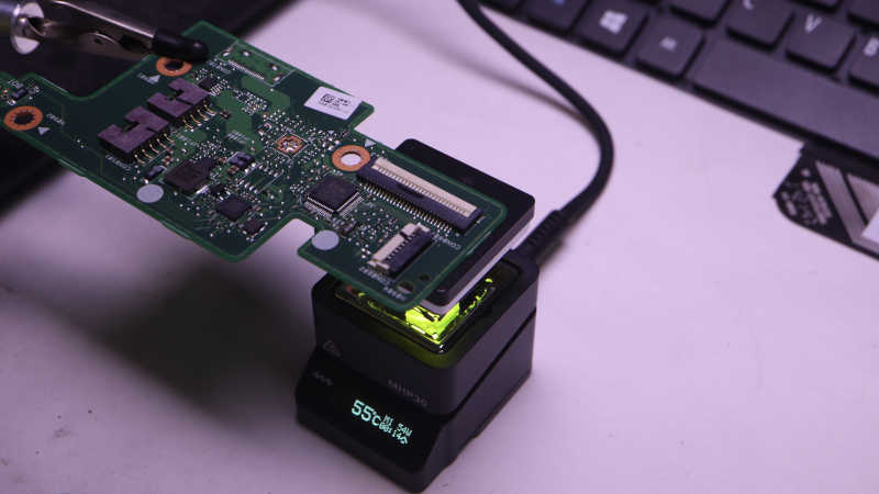
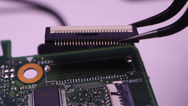
I would have to either buy my own 26-pin connector or try to reuse the one I had. Since I like to salvage and reuse, I’m trying the reuse option first. The circuit board was placed on my MHP30 mini hot plate (*) and brought up to temperature.
The white plastic latch started to turn brown by the time solder melted, but all plastic components still seemed to be in their proper shape when I lifted this connector free. I think this is good enough for a try. If I fail with this connector, then I’ll spend money to buy another.
I’ve verified that I now have full CircuitPython programmatic control over all input and output functionality available within the control panel of a Canon Pixma MX340 multi-function inkjet. The point of the exercise was to see if I could get this far. I would love to repurpose this control panel for a future project, but that is secondary. The perfect project would be one that needs a small LCD, numeric keypad, and a handful of task-dedicated buttons and LEDs. While I wait for such a project to come up, I could have some fun with a less serious project.
My friend Emily created Cat and Galactic Squid for me to use as demonstration content of my ESP32 composite video output library. I love this colorfully cheerful animation and have used it as test subject for several other projects. However, the MX340 LCD is monochrome and has only 196×34 pixels so I could not use the original cat & squid directly. I had to downscale it in an image editor, and manually fix up all the broken edges from such drastic down-sampling. And while I’m switching to monochrome, the cat is now modeled after one of Emily’s current cats “Hobie” with a suitable black and white tuxedo pattern. Getting the handful of pixels to remotely resemble a cat required that I go online to search for “pixel art cat” for some guidance.
There weren’t enough pixels to convey movement, so cat and squid would remain static. Neither were there enough pixels for that Saturn-like planet and a galaxy in the background, so the simplified version will only have vaguely circular dots of different diameters moving at different speeds for a parallax effect. Ideally I could use CircuitPython’s sprite bitmap compositing engine displayio to put all these elements together. Unfortunately I couldn’t figure out how to make this LCD compatible so I wrote my own crude compositing routine.
I originally thought I’d write this as an entirely separate MX340 demo app, but I realized I could incorporate it into the existing key echo feedback test app: a “screen saver”! Monochrome LCDs don’t really have burn-in issues that need saving, but it’s an user experience paradigm I can leverage. I switch to this animation if there aren’t any key presses for a while, and switch back as soon as a key is pressed. Integrating cat & squid was a nice bonus bit of CircuitPython practice.
I bought some FPC (flexible printed circuit) cables and connector breakout boards from Amazon vendors so I no longer have to solder wires directly to my salvaged Canon Pixma MX340 multi-function inkjet control panel. The first FPC breakout board went on a perforated prototype board to host a Raspberry Pi Pico. Up until this point I had been using Adafruit’s KB2040 board. But since they’re both based on RP2040 chip and have CircuitPython support, switching my code to run on a Pi Pico is a minor task of changing over a few pin names.
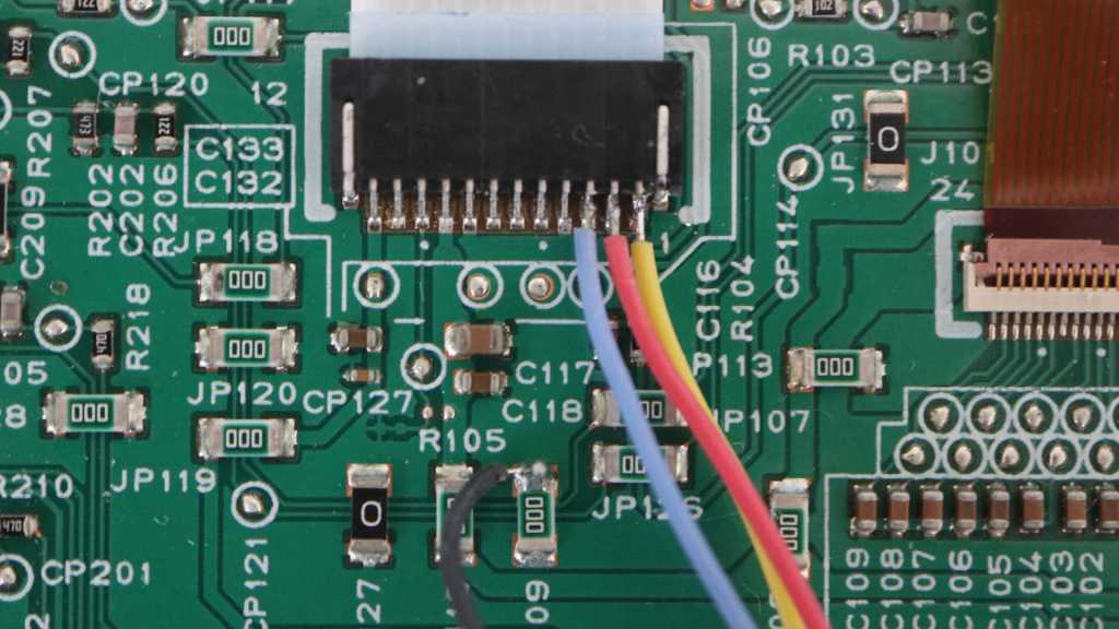
Soldering to the FPC breakout board with its 0.1″ (~2.54mm) pitch was far easier than the 1.0mm pitch of soldering directly to the control panel. Which meant I finally got around to connecting five wires that were previously not connected:
5 volt DC wire to supply WiFi LED
LED+ for Power LED, in series with an 100 ohm current-limiting resistor already on board.
LED+ for Alarm LED, also with resistor.
Power button that is pulled to ground when pressed.
Stop button that is pulled to ground when pressed.
My CircuitPython code had provision to set the appropriate bit flags to manipulate the WiFi LED, but I hadn’t tested it until this point due to lack of +5V power. I was happy to see it worked, but I doubt I would find a use for it. As it originally shined into a clear plastic light guide and thus pointed in an opposite direction from the rest of the control panel.
And I hadn’t dealt with the remaining four wires at all, as I considered the two direct-wired buttons and two direct-wired LEDs fairly standard microcontroller fare. And indeed, there were no surprises after I declared two CircuitPython digitalio pins for those LEDs and a keypad instance to read (and debounce) those two buttons. All worked as expected on the first try.
I updated my test app to toggle power LED upon presses to the power button, and the same for alarm LED and the stop button. The “In Use/Memory” and WiFi LEDs blink their own separate heartbeat patterns. And the LCD displays status of key matrix scan code activity: every time one of the K13988-scanned button is pressed, its name is displayed on the LCD. It makes for a simple demo to prove I have complete control over all electronic functionality of this salvaged control panel. Now this control panel waits for a project that could put it to good use but while it’s waiting, I went ahead with a project that puts it to silly fun use.
I’ve been using my salvaged Canon Pixma MX340 multi-function inkjet control panel as test target hardware for learning CircuitPython. After exposing a keyboard event queue, my first attempt at a CircuitPython library is now feature-complete. Well, it is on the software side. The hardware side still need help but I’ve recently learned it is a problem I can solve by spending money.
Up until this point, I had been exploring control panel communications by soldering wires to the back side of its FPC (flexible printed circuit) cable connector. This was essential because I still need the cable installed for main logic board and control panel to talk to each other. Now that I have a code library to let any CircuitPython microcontroller take the place of the main logic board, it means I can actually use my own cable and avoid the need to solder any more wires to these pins.
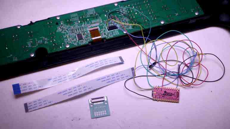
There are vendors on Amazon selling breakout boards for popular FPC sizes, so I searched for 12-pin 1.0mm pitch FPC connector breakout to see my options. Some of these listings were for a bare circuit board, so I picked this one (*) as it had the connector already soldered and its output pins were spaced out in a prototype board friendly 0.1″/2.54mm pitch format. Those output pins were also already numbered, which I wanted even though it made the next step a bit harder.
I then searched for a short piece of FPC I can use to connect my salvaged control panel with the breakout board. There were again multiple vendors offering 1.0mm pitch 12-position cables, with 150mm being a popular length. I just had to choose if I wanted “A-type” (*) with metal contacts on the same side of the ribbon on both ends, or if I wanted “B-type” (*) with metal contacts on opposite sides of the ribbon. And here I got stuck. I didn’t know which side the breakout board’s connectors made their metal connections. If I chose wrong, I could flip the board over to make the connection, but that would mean the pin numbers would become reversed. That is a recipe for confusion and potentially project-killing mistakes. After waffling back and forth for a while, I decided on the solution of buying both sets. I felt spending a few extra dollars was worth the guarantee of consistent pin numbers.
In Emily’s article, she compared modern electronic ignition with electromechanical ignition from BC (before computers) era of cars. The distributor diagram is a pretty good explanation why I couldn’t do very much with an old ~1950s Chrysler ignition coil my neighbor had sitting on a shelf: I needed something to interrupt power to the ignition coil so its primary winding’s 12V field can collapse and induce high-voltage in its secondary winding. Since I usually play with electronics manipulating 5V or less, at well under 1A, I didn’t have anything on hand suitable to handle such power.
However, a modern electronic ignition coil has that switch built-in. (The “Igniter” box in the LS1 Coil diagram of Emily’s article.) So to repurpose a retired coil+plug only requires a 5V, low-current, digital control signal to be sent on its IGT pin. Now that’s something Arduino tone() can do easily and help Sparky find its singing voice.
So what’s next? There was a bit of confusion between Emily and I about Arduino tone(). She referred to an installed library, but I found it as a built-in function. Investigating this confusion led me to https://github.com/bhagman/Tone where I learned we were both right. There’s a full non-core version that Emily had to install into her (presumably older) Arduino IDE, and Arduino had incorporated a simplified version of this library into core which is what I found. The simplified version can only generate one voice. The full version can generate more voices: one per hardware timer on the AVR chip. ATmega8-based chips have two timers so two voices. ATmega328P (like that on the Arduino Nano I used) can do three voices, and an ATmega1280-based board like the Arduino Mega can control six spark plugs. Useful facts to keep in mind whenever Emily or I get our hands on more retired electronic ignition coils.
My CircuitPython learning project was to communicate with the K13988 chip on board a salvaged Canon MX340 multi-function inkjet control panel. The follow-up project, currently in progress, is to convert my jumble of experimental and exploratory code into something resembling an usable library. It looks pretty good after I rearranged all the setup/cleanup into context manager syntax, but then I realized I was missing a big piece: key press events. I had been printing key codes to serial terminal as they come in, but that was no way to write an API!
For precedence I looked into CircuitPython keypad class. I had expected this to be an opportunity to learn about Python events and event listeners, so I was surprised (and mildly disappointed) to find an event queue that client code is expected to poll on a regular basis. Well, at least I know how to implement such a thing, and Python standard libraries should make it pretty easy to implement.
I could reuse their Event class to report my key press events, but the EventQueue class itself is locked away inside Adafruit implementation and not available to me. I went looking for an existing Python standard library queue and the first search result seemed to be far more complex than I had expected. Turns out that particular queue was designed for coordination across threads, overkill for this purpose. I just need the basic deque (double-ended queue) class to emulate most of Adafruit’s EventQueue.
For my first draft I decided against implementing a separate object to expose keyboard event queue. I’ll expose a get_key_event() method which should serve basic scenarios well enough until I see justification to do more.
I’ve got CircuitPython code to interface with control panel of a Canon MX340 multi-function inkjet, and gradually refining my crude experimental code into an actual reusable CircuitPython library. Using events for synchronization and exposing property setters was just the start.
A major change is to separate communication infrastructure from code that utilizes such infrastructure. For example, I’ve had code in there blinking the “In Use/Memory” LED to let me know everything is still running. I consider code to transmit the LED control bytes to the NEC K13988 as infrastructure, and the timing loop to toggle LED on and off to be application code. I have a separate asynchronous task that continually updates the LCD content for the same reason, and that should be separated out as well. During the experimental phase I could just mix code in there in a big jumble. A global space where any bit of code can call any other bit of code. But now I have to think about which methods should be part of the API and which are internal implementation.
To reflect this division, a minor change is to rename several methods with a leading underscore. This is a “weak internal” indicator by Python convention. They are understood to be for internal use though there’s no language level mechanism preventing callers from accessing them. I guess this means they can be changed without becoming a public API breaking change? Reading the linked section of PEP 8, I saw there’s also a way to declare public interface with __all__. As per Python tutorial on module imports, this works in conjunction with “from [module] import *“. I don’t understand enough about Python modules yet to know if it’s applicable to my project.
After I performed this separation, I can clearly see a set of startup and cleanup tasks that have to run before and after application code. This sounds like a job for context managers! I can set up all the infrastructure by using an async with statement, and all application code can run within its scope. I first tried to write my context manager with the generator syntax that has a single yield for application code, but that failed: I need to decorate such a generator with @contextmanager to apply supporting infrastructure from contextlib, which has not been ported to CircuitPython. Oops! Fortunately I can still implement a context manager by falling back to using special method names __aenter__() and __aexit__(). Once implemented, I can apply even more lessons from my recent study session, implementing a clean separation between my test code from my NEC K13988 infrastructure.
I’ve been writing CircuitPython code to interface with the NEC K13988 chip on board a salvaged Canon MX340 multi-function inkjet control panel. At first I only intended to explore if it was even possible to repurpose the panel. Now that I’m confident it is possible, I decided my follow-up would be to factor my code to extract a reusable library that could potentially support multiple projects. As expected, the task of making the code neater taught some valuable lessons.
Asynchronous Event
I had a few asynchronous tasks declared and running, each handling one aspect of K13988 interface, but sometimes they stepped on each other’s work. I learned about Lock() earlier but I had additional synchronization needs that didn’t fit a Lock(). Some pieces of code needed to wait for certain other startup conditions to be met before it ran. For example, I needed to wait for the K13988 to wake up enough to send data bytes before I could successfully transmit commands to it.
In the constructor, I set a boolean:
self.in_startup = True
And in my data transmission code, I check that boolean value in a loop:
while self.in_startup:
    await asyncio.sleep(0)
That would put data transmission on hold until I receive my first byte from K13988, at which point I could flip that boolean value:
This worked, and I guess it isn’t terrible. But there was a better way. When I read through Python documentation during my study session, I discovered this pattern fit Event from the asyncio library.
Using events, I declare one in the constructor:
self.transmit_startup = asyncio.Event()
And in my data transmission code, I will wait for this event before proceeding:
await self.transmit_startup.wait()
Permission to proceed will happen once I receive my first byte from K13988:
# First successful read complete, exit startup mode
self.transmit_startup.set()
This was a simple case, and I’m glad it helped me learn to add to my toolbox so I am ready to tackle more complicated scenarios in the future.
No Async Property Setter?
This control panel has four LEDs. Two are wired directly to main logic board connector pins, two are controlled by K13988. I thought I would add Python property setters for those two LEDs, following precedence of setting a CircuitPython digitalio output pin value. But it seems like I can’t expose a property setter to turn a LED on like this:
k13988.in_use_led = True
The problem is that such LED update would require sending two command bytes to K13988, and that is an asynchronous operation which meant I have to somehow declare async on the property setter and somehow use await in the caller. If there’s a Python syntax to declare such a thing, I couldn’t find it. For now the best I can do is to implement an explicit method to set LED:
await k13988.in_use_led(True)
Not terrible, just not as straightforward. I can live with this while I learn more asynchronous Python and maybe I will learn something that’ll let me come back to fix this later. In the meantime I have more cleanup work to do.
I typically learn new things by alternating between hands-on time and reading study time. After reading through (though not necessarily understand all of) several Python Enhancement Proposals ending with PEP 492Coroutines with async and await syntax I’m ready to switch back to playing in a code editor. My CircuitPython practice project is to interface with a control panel I salvaged from a Canon MX340 multi-function inkjet. I’ve successfully accomplished that with a few rough test programs, but I didn’t understand what I did, thus the study session.
Now that I understand a bit more of Python generally and CircuitPython in particular, I want to aim higher for my project. Instead of a bunch of test code written on the fly whenever the next idea occurs to me, I should go in and organize things sensibly. I want to learn from Adafruit’s collection of CircuitPython libraries to interface with hardware peripherals, following their lead to reorganize my MX340 jumble into a self-contained piece of reusable code. I believe the primary reference would be Adafruit’s CircuitPython design guide for community-contributed libraries. I don’t understand all of it yet, but I expect to learn by doing and learn from my failures to conform to the design guide. I do not realistically expect my MX340 CircuitPython library to be used by many others. The point of the exercise is to learn how to build such a library, so that a future library I write may actually be useful to others.
Here are my updated goals:
A class to handle serial communication with the NEC K13988 chip on board the control panel, with three functional areas:
LCD screen: following precedence of Adafruit’s rgbmatrix class, either create a byte array for raw frame buffer or use a caller-allocated byte array. Implement a refresh() method which will initiate sending frame buffer data to K13988 for display.
An optional class to wrap the above LCD raw byte array into a MicroPython-style FrameBuffer class. Implemented as adafruit_framebuf with a custom frame buffer manipulation class. This is optional and not part of #1 because the caller may wish to manipulate the byte buffer directly.
Some example code utilizing the above.
After writing example code, decide if it’s useful to add one more: An optional class as single point of contact for the entire control panel. Exposing a single event queue integrating direct-control buttons (“Power” and “Stop”) with K13988-scanned buttons, and properties for direct-control LEDs (“Power” and “Alarm”) peer of K13988-controlled LEDs (“WiFi” and “In Use/Memory”)
As I’m reading through several Python Enhancement Proposal (PEP) documents, I have to keep in mind that I don’t have to understand everything on my first read through. And I also have to keep a goal in mind so I don’t get too distracted. For this session, the motivation was copy/pasting “async with” from example code without having any idea what those keywords meant. PEP 380 was the last in my list of self-assigned prerequisite readings, but now it’s time for the main attraction: PEP 492 Coroutines with async and await syntax. After completing this study session, I have a much better understanding of what “async with” does.
It was interesting to follow Python evolution on this front. My prerequisite PEP reading all discussed generators and coroutines as a specific type of generator. In PEP 492 they laid out the reasons for separating out coroutines as its own concept. The underlying implementation of coroutines still uses many pieces of generator infrastructure, but the language will now treat them as different things. As part of this evolution, a large part of this document discussed is devoted to “Design Considerations” of alternative approaches, and “Transition Plan” for maintaining compatibility with pre-492 coroutine syntax.
One decision I found disappointing was that debugging features are disabled by default. I understand the motivation to ensure debugging features do not impact production code, but I think leaving them out completely is going too far. Beginners who most need feedback from Python runtime are not going to know they need to set an OS environment variable PYTHONASYNCIODEBUG.
Syntax for asynchronous comprehensions could be provided, but this construct is outside of the scope of this PEP.
I don’t like Python comprehension shorthands and I’m glad there to see this PEP did not add one. It’s possible this text meant only exactly what it says, but in my professional career I’ve used “out of scope” as a polite rephrase of “I don’t like this idea and I’m not doing it.” It made me smile to think the PEP author might be doing the same here.
I’ve dipped my toes into writing Python code for asynchronous execution, and encountered a lot of new concepts that I felt I need to study up on. One of the keywords I wanted to understand better was “with“, which took me to context managers. Another item on the list of mystery was “yield from“. I recently learned “yield” in the context of coroutines, and I knew “from” in the context of loading Python modules, but they didn’t make sense together. Thankfully I found PEP 380 Syntax for Delegating to a Subgenerator, where my confusion was explained by the fact it had nothing to do with loading modules.
When I read up on coroutines, it took effort for my brain to absorb the concept of code execution interleaved between caller and callee. It was a foreign enough concept my brain didn’t flag a consequence of Python’s special treatment: the “yield” relationship is limited to one layer of interaction. What if we wanted to refactor a chunk of code, that included a “yield“, into another coroutine? Things quickly get messy. If only there’s a way to extend yield to multiple levels, and this is the problem PEP 380 wants to solve with “yield from“:
The rationale behind most of the semantics presented above stems from the desire to be able to refactor generator code.
Reading through the PEP, I was not happy to see “StopIteration” exception was used to convey a return value out of “yield from“. I was taught in the school of “exceptions should be exceptional” and here it is just a normal non-exceptional code return path. My initial reaction was tempered by learning StopIteration is how Python iterators (which are used all the time) signal a halt. I think my instinctive negativity came from experience with languages where exception handling incurs a significant performance overhead. Judging from what I’ve learned here, either Python exceptions incur no significant penalty or Python designers feel it is an acceptable cost.
For what it’s worth, I was not alone in my negative impression. Using StopIteration to convey return value was also disclosed under “Criticisms” sections of PEP 380 and dismissed as “without any concrete justification”. Shrug. But I was thankful another criticism was dismissed: looks like there was a suggestion to use syntax of “yield *” and I’m glad it didn’t go in that direction because it’d end up as another special syntax very difficult to look up. Searching on * would be a disaster as it is popularly used as a query wildcard character. From this perspective “yield from” is far superior and it only meant typing three more characters. I’m much happier with this approach and I’m glad to see it as I continue my PEP study session with PEP 492.
I don’t like Python shorthands that are so short, it leaves a beginner up a creek without any keywords they could use for searching and learning. But I’m OK with shorthands that clean up code while still leaving something for a beginner to look up. Such is the case with PEP 343 The “with” Statement. I’ve been using “with” in Python for a while, but never really sat down to understand what’s going on when I do. Thankfully there is a keyword I could use to find appropriate documentation.
My introduction was in the context of example #2:
with opened("/etc/passwd") as f:
    for line in f:
        print line.rstrip()
Opening a file for data operations, “with” guarantees all cleanup will also be handled behind the scenes. PEP 343 explains the problems it intended to solve, and explaining how this convenience is handled behind the scenes. There were two explanations that I could follow. The first explains using an implementation specified with a set of methods with special names “__enter__()” and “__exit__()“. I understood Python will look for these names under conditions specified in PEP 343. Then the same concept was rewritten in a way that built upon PEP 342: a context manager called upon via with can be implemented as a generator that calls “yield” at a single point within a “try/finally” block. This neatly packages all associated components together. Any setup code runs before “yield“. Within the “try” block, “yield” hands control over to client code. (In the above example, the “for” loop reading text in a file line by line.) Then code inside either “except:” or “finally:” can cleanup after client code completes.
I like this pattern, ensuring setup and cleanup code can be kept together while allowing other code to run in between them. While I have not yet fully absorbed Python generators, I think I understand enough of this particular application to appreciate it.
Coverage of this topic in the official Python tutorial is under “Predefined Clean-up Actions” within the “Errors and Exceptions” section. As appropriate for a tutorial, it focuses on how to use it and how it’s useful and leaves all the history and design thinking and implementation nuts and bolts to PEP 343.
When learning about a Python feature like coroutines and generators, I found it instructive to flip back and forth between different ways a feature is represented. It’s nice to get the context of a feature and its evolution by reading its associated Python Enhancement Proposal, and it’s good to see how the official Python tutorial presents the same concept after the PEP process was all said and done. However, I want to take a side detour because the generator tutorial section was immediately followed by generator expressions and that made me grumpy.
Some simple generators can be coded succinctly as expressions using a syntax similar to list comprehensions but with parentheses instead of square brackets.
I am personally against such alternate syntax for the reason they are extremely hostile to people who don’t already know it. When I came across a generator and didn’t know what it was, I was able to search for keywords “yield” and “send” and get pointed in the right direction. But if someone comes across a generator expression or a list comprehension and didn’t know what it was, they have nothing to search on. The expression is enclosed by parentheses or square brackets, commonly used throughout the language. Inside the expression are normal Python syntax, and searching on “for” would just get to those features and not anywhere close to an explanation for generator expression or list comprehension.
I get that whoever pushed this through Python loved the option to “code succinctly” but my counter position is: No! Go type a few more characters. It won’t kill you, but it’ll be tremendously helpful to anyone reading your code later.
[(x, y) for x in [1,2,3] for y in [3,1,4] if x != y]
As a Python beginner, I had no idea what this syntax meant when I first saw it. I see two “for” loops, but this isn’t just a “for” loop, I see an “if” statement, but I didn’t know what that decision affected. (There’s no obvious “then” in this if/then.) Beyond those keywords, there are just variables and parentheses and square brackets. I had nothing to put into a search to point me towards “list comprehension”.
Python list comprehension tutorial said the above was equivalent to this:
combs = []
for x in [1,2,3]:
    for y in [3,1,4]:
        if x != y:
            combs.append((x, y))
If I didn’t understand this code, I could search “for” and learn that. Same with the “if“, and I can see the result of the decision affected whether the value was appended to a list. This is way more readable, it wasn’t even that much more typing.
Was list comprehension (and generator expression) worth adding to Python? I guess enough people in decision-making positions thought yes, but I disagree. I don’t understand why Python is considered beginner-friendly when horribly beginner-hostile things like this exist. I don’t think they should be in the language at all, but that ship has long since sailed. I can only shake my fist, yell at cloud, then return to my study.
I got a spark plug to sing a song, but it was singing out of tune and I didn’t know why. I barely know enough about music to get this far. My friend Emily had more sheet music reading skill and offered to double-check my music translation. If her translation sounds good, then we’ll know the problem was my sheet music translation. If her translation also sounds odd, we’ll know the problem is with my timing code controlling spark frequency.
I replaced my version of the song with hers, and it sounded great! So that’s settled: Sparky’s first performance sounded bad because I didn’t know how to read sheet music. I also received feedback that the way I represented music in my Arduino code was peculiar. No argument from me, because I wrote it out of ignorance and it was what I could hack together at the time. Emily then asked if there was a reason why I’m not using tone() if I’m using an Arduino anyway. The answer was that I didn’t know it existed.
Prompted by this question, a bit of searching on “Arduino tone library” found a GitHub repository at https://github.com/bhagman/Tone, whose README explained it was a library to use AVR timers to generate 50% duty cycle square waves of a specified frequencies along with a list of #define that mapped musical notes to frequencies. It also said a single-timer version of the library has been incorporated into Arduino core, so for single-voice applications like Sparky we wouldn’t even need to install an additional library.
I thought the 50% duty cycle (half of time signal is on, half off) might be a problem, because I’ve been using 0.5ms signal pulses and leaving the pin off the rest of the time. I looked in the tone library but wasn’t familiar enough with AVR timer configuration registers to understand how I might convert it over. Then I remembered the always-useful mantra: check the easy thing first. Maybe Sparky doesn’t mind if the trigger pulse was longer.
Since the single-timer version of tone was now built into Arduino, I looked for Arduino built-in examples illustrating its use. I found “Examples/02.Digital/toneMelody” which was designed to work with a piezo buzzer. I pointed it to Sparky’s IGT pin and heard it play the little melody. Great! Sparky doesn’t mind longer IGT pulses and I can throw out all of my hacked-up music-hampering playback code and just use tone(). I don’t even need to struggle with sheet music or convert them to MIDI notes anymore, I can play songs other people have already translated for tone() playback. I found several collections and the first collection with its own take on Beethoven’s “Ode to Joy” is https://github.com/robsoncouto/arduino-songs. I gave to Sparky and yeah, way better than my version and a lot easier too. I wish I knew tone() existed a few days ago, but at least I know now. This tone() music earned Sparky 15 minutes of fame on The Autopian.
I think I’ve worked my sparkly distraction out of my system, time to return to my Python study. This was motivated my CircuitPython experiments running on RP2040 microcontrollers. CircuitPython may be a reduced subset of Python, but it nevertheless incorporated many concepts that I have yet to grasp. Thus the study session, which dug through multiple PEP (Python Enhancement Proposal) design documents. Here are my notes after reading PEP 342 Coroutines via Enhanced Generators.
I was not familiar with coroutines, but I found a helpful explanation within Python glossary: “Coroutines are a more generalized form of subroutines. Subroutines are entered at one point and exited at another point. Coroutines can be entered, exited, and resumed at many different points.” I was familiar with functions, which has a single entry point and multiple exit points. (Each return is an exit.) When I read about “resume” in context, my first thought was of a function calling another. The parent caller function pauses execution waiting for the child callee function to run. Which is true, but Python coroutines have more points of interaction with each other. The caller can send additional data to the callee, which receives that data via yield. And they each maintain their internal state while this went on.
Why do we even want this? At surface I thought the same could be accomplished by standard nested loops, but example #2 in the PEP (JPEG contact sheet creator) helped me understand. Yes, maybe the pattern of execution could be replicated by nested loops, but that meant a single function has to track all variables involved in every nested loop. A coroutine, in contrast, can be written to encapsulate information for just one layer.
Here’s my pseudocode to replicate example #2 with nested loops:
for each page of contact sheet
  for each thumbnail on contact sheet
    for each JPEG
      generate thumbnail
    add thumbnail to contact sheet
  write page of contact sheet
If I want to process a bunch of JPEG differently, resulting in a different summary output JPEG, I would write a new function that has the different second loop but has the same innermost and outermost loops. With coroutines, I can get the same result by swapping out the thumbnail_pager coroutine and continue using the rest without making any changes to them or duplicate code.
I think I see the advantage here for independent code modules, but it’ll take a while for my brain to adapt and add this tool to my toolbox. During this transition period I’m likely to continue writing my code as nested loops. But at least this understanding helped me understand Python context managers. But before that, a complaint from grumpy Python student.
I’m playing around with a retired Denso ignition coil-on-plug pack. After gaining a marginally better understanding of its limitations, I will convert my test circuit to a proof of concept discussed with my friend Emily Velasco (who gave me this thing to play with): make it into a silly music instrument I’ve named Sparky Danger Organ.
This ignition coil came out of a Toyota Sienna’s V6 engine which probably redlines somewhere around 7000 RPM. At 7200 RPM this coil would be firing sixty times a second, but 60Hz is on the low side for music-making. So my workbench experiments were to find out how much faster I can drive this thing and I think it’s somewhere between 1 kHz and 1.5 kHz. (There isn’t an exact number because sparks fade out rather than abruptly cut off.) But judging from Wikipedia’s list of piano notes and their frequencies, even a limit of 1kHz should be enough to represent an interesting range of music notes.
Putting all that together gave Sparky Danger Organ its first performance, and it’s definitely along the lines of a bear riding a bicycle: the novelty is not that Sparky Danger Organ is a great music instrument, but that it can make an attempt at all. There’s only a very limited range of frequencies where it sounds like an acceptable tone, and even within that range the music does not sound great. I may have made mistakes translating piano sheet music into Arduino code. Or maybe the frequency I generated is not what I had intended to generate, throwing the instrument out of tune. The top suspect along these lines is the possibility Arduino framework is doing work behind the scenes and adding delays throwing off the output frequency.
Despite those potential problems, it was a successful proof of concept. Emily has some ideas on how to troubleshoot this device. [UPDATE: the solution was to throw away all of my crappy code and use Arduino tone().] And if we ever get our hands on one or more engine’s worth of ignition coils, there may be a Sparky Danger Orchestra.
Experiment to control a Denso ignition coil-on-plug module was far more successful than I had expected. It was a lot of fun! Because high voltages are involved (the very core purpose of an ignition coil…) the first round was done on my garage floor, away from most of my electronics components and equipment. Now that I have gained some confidence it won’t send sparks shooting everywhere, the test rig was moved to my workbench to get some measurements.
These numbers won’t be very good, though. It would be better if I can get an idea of what parameters are important to an ignition coil and what values to expect from a data sheet, but I had no luck finding such official engineering information. Searching for “Denso 90080-19016” found many auto parts suppliers offering to sell me more of those units and/or non-Denso substitutes, but no details beyond which cars the part would fit. Furthermore, this ignition coil was retired from a Toyota Sienna due to error codes relating to the ignition system, so it is probably not functioning to spec anyway.
Its power supply requirement is my biggest unknown. I had tried connecting it to a lithium-ion battery power pack delivering approximately 12 volts, but its power protection circuit believed there was a short circuit and cut power. My bench power supply has a red LED indicating “amperage limit reached”. When using it to power my experiment circuit, that red LED blinks every time the coil fired a spark. So clearly this coil has a brief but very high current draw. As a digital logic person, my understanding of solving such problems only went as far as “add capacitors”. I had some salvaged electrolytic capacitors available and connected them. I installed so much that the inrush current upon plugin would trigger power protection even before the coil started firing. If I disconnect power while running the coil, I can hear those capacitors supply enough to spark three or four times (each less energetic than the last) before fading out. And even with these capacitors, the brief current draw is still high enough to trigger errors. I’m either not using the right types of capacitors, or of the wrong values, to smooth this out. Such is my ignorance of proper electric power system design.
I had thought if the power requirements were simple enough, I could power the whole thing with a USB power bank. With a boost converter to kick USB 5V up to supply the coil at 12V. But given these high draw symptoms, I am skeptical an Amazon lowest-bidder DC boost converter will survive this coil’s demands. I will continue using a lead-acid battery that has (so far) tolerated such abuse.
The next set of experiments concern IGT signal duration. My experiments started with 2ms as a value I eyeballed from a blurry oscilloscope screen capture. If I want to drive this coil faster, I need to know how short of an IGT pulse I can get away with. I modified my Arduino sketch to use the knob to adjust signal duration, and output the current duration to one of my less-precious computers. The results were:
2ms: initial guess that worked.
~1ms: start to hear a difference in the sound of the spark.
~0.8ms: sound of spark is weaker, and I no longer see IGF LED blink. So the coil thinks the spark is no good beyond this point to run an engine. Thankfully I’m not running one.
~0.4ms: even weaker spark sound, and spark generation becomes intermittent.
~0.2ms: no spark at all, just worrisome whining noises from the coil.
Those are the duration of IGT signal pulses with the caveat that I measured these with a constant 17ms (“redline”) between pulses. As the time between pulses shrink as well, it affects behavior in response to IGT signal pulse. The two variables are related, but I don’t understand exactly how. And without a good way to quantify results it’s not very feasible for me to map out a 2D graph charting how those two variables interact.
Lacking such metrics for better understanding, I settled on a maximum of IGT pulses 0.5ms in duration, and 0.5ms between pulses. In other words, an 50% duty cycle square wave at a frequency of 1kHz. Referencing Wikipedia’s chart of piano note frequencies, an upper limit of 1 kHz should still be enough for a bit of silly fun.
The problem with deciding I need to sit down and do some reading is that I’m vulnerable to get distracted by something shiny. Or in this case, something sparkly. Some time back I learned how voltage boost converters worked for laptop screen LED backlights. A little after that, it occurred to me ignition coils in modern electronic ignition engines must be boost converters as well. Except instead of driving a bunch of LEDs in series, an ignition coil raises the car’s 12V DC up high enough to jump across a spark plug gap. I thought it might be fun to try driving a coil in a non-automotive context and discussed the idea with other local makers. I was too cheap to buy a new coil just for this experiment, because I knew eventually someone would replace their car’s ignition coil and I can ask for the old one. That day has come: my friend Emily Velasco let me know she was going to stop by with a Denso ignition coil-on-plug module with associated spark plug, recently retired from her parents’ Toyota Sienna.
Research
The first step is information gathering. Thanks to ubiquity of Toyota vehicles, Emily found a pinout diagram for the ignition coil. This module has four pins. Two for power (+12V DC and ground) and two for signal (IGT and IGF). Toyota’s official workshop service information would have more details on its operation and troubleshooting, but I don’t have access to that. Fortunately there are other web resources like TOYOTAtech’s How to Find Toyota Ignition System Faults Fast! Dotting the IGFs and Crossing the IGTs.
According to this page “IGT” (I guess “ignition trigger”) is a signal from ECU telling the coil to do its thing, and “IGF” (guessing “ignition feedback”) is a signal from coil back to ECU to signal successful operation. Both operate with +5V DC logic. IGT is usually at ground level and briefly raised to +5V by the ECU to call for spark ignition. Looking at the blurry oscilloscope screen capture on TOYOTAtech’s page, my best guess is raised for approximately 2 milliseconds. In contrast, IGF is usually up at +5V DC and the coil pulls it low for roughly 1 millisecond to signal successful spark generation. This open-drain system allows multiple coils to share a common IGF line back to the ECU.
Circuit Board
Armed with this knowledge, I built a quick experiment circuit out of components immediately available at my workbench. Emily helped me by making a connector as CAD practice, for which I was thankful. My board’s output side needs to interface with that connector. On the input side, I needed two voltage levels: +12V DC for the coil and +5V DC for the signal. I have a 3S Lithium-Ion battery pack for 12-ish volts, but its battery management system (BMS) freaked out at the workload. As a backup, I switched to an old-fashioned lead-acid battery. For 5V I used the most expedient thing: an Arduino Nano with its USB socket and +5V DC output pin. To run the coil it will be connected to a cheap disposable USB power bank instead of a computer.
The experiment circuit had two input paths to IGT, switchable by a jumper. The first path is a “manual override” test mechanism with a small push-button switch. Once everything is hooked up, a push on the switch will raise IGT to +5V DC. If there is no spark, we have to backtrack and see what went wrong. If there is a spark, I can move the jumper to the other input path: pulse-generating Arduino Nano.
I’ve already established it needs to raise the line to +5V for approximately 2 milliseconds, but how long should it wait between pulses? A Toyota Sienna should idle somewhere just under 1000 RPM, and redline somewhere around 7000 RPM. This coil is responsible for a single spark plug. As a four-stroke piston engine, it would need to spark once every two revolutions of the crankshaft. The math then works out to: 1000 revolutions/minute * 1 minute/60 seconds * 1 spark/2 revolution = ~8.3 sparks/second. Invert that value to arrive at 120 milliseconds between sparks. Doing the same math for 7000 RPM arrives at 17 milliseconds between sparks. So I would expect this coil to reliably spark once every 120ms to 17ms. For the default program, I programmed the Arduino to raise IGT to +5VDC for 2ms then wait 120ms before repeating.
Coil Arrives
I started building the experiment board immediately after Emily told me she would stop by, hoping to have something ready by the time she arrived. So it was slapped together with speed as the utmost priority and everything else (visual neatness, design elegance, and… ahem… electrical safety) relegated to be dealt with later. We connected the coil’s four wires to my test circuit, and it was time for the moment of truth.
I tapped the switch, and we saw a spark. Woohoo! We powered down the system and moved the jumper. Once powered back up, the Arduino sent its pulses and we have a steady stream of sparks. Success!
Enhancements
I honestly expected a lot more debugging before getting to this point, so I didn’t have anything else prepared. Emily suggested that we connect a potentiometer to the system for interactivity, so out came the soldering iron and associated tools. Emily has built a lot of projects with potentiometer knob adjustments so she handled that addition. As the code monkey I updated my Arduino code to read knob position so we can adjust from “1000 RPM idle” to “7000 RPM redline”.
Emily also fixed a problem with my board: I had connected a LED to IGF but it stayed dark. Reviewing the circuit I realized out of habit I had set it up to shine whenever IGF is high: but the coil never raises IGF to high! It pulls IGF low to report a successful spark. Emily added a 1k pull-up resistor and rewired the LED so it shines when IGF is low.
We connected everything back up and the adjustment knob worked wonders. We can “rev up” our system and it was fun, with Emily capturing a few video clips. Unfortunately the IGF LED stayed dark, but it didn’t dampen our enthusiasm. Now that the coil is up and running under conditions approximating its designed purpose, we enter the “screwing around” phase pushing it beyond original operating range.
Adventuring Beyond Spec
Emily asked for a fluorescent tube, but my house had almost entirely converted to LED lighting. I had but a single remaining tube and it was only still there because I haven’t figured out how to open up its enclosure. Emily figured it out in five seconds and pulled out the tube, connecting its ends in place of the spark plug. The ignition coil was able to act as a (poor) fluorescent tube ballast dimly flashing the tube. (The room had to go dark for Emily to shoot that video.)
After this fluorescent tube experiment, we reinstalled the spark plug and made a fascinating discovery. With no other (intentional) changes, the IGF LED now blinks in sync with sparks as originally expected. We have no idea why. Perhaps something about the workload of driving a fluorescent tube? This coil and plug was replaced because the Toyota Sienna’s engine control unit (ECU) reported codes for ignition issues. It’s possible cylinder combustion was working properly but poor IGF reporting triggered the malfunction indicator light (MIL). We agreed if this was the case, it obviously meant Toyota/Denso must add a fluorescent tube to their official list of repair tools.
Emily tried to see if this spark can light a sheet of paper on fire. There was a lot of glowing, charring, and pitting, but it took persistence before she got a real flame. There are far more effective ways to start a fire! But it did make us wonder if it’d be practical to build a crude electrical-discharge machining (EDM) system out of an ignition coil. That idea has been added to the ever-growing project to-do list.
The most promising experiment was revving this thing far beyond “redline” by shortening time between pulses below 17ms. To go even faster, we reduced the duration of IGT pulse itself. This quickly extinguished the IGF LED, which was the coil’s way to complain things are going too fast for a good combustion-initiating spark. But that’s OK, because we’re not here to ignite air-fuel mixtures, we were trying to turn it into a silly and pointless musical instrument. Still, there was a limit. We started losing the spark (and our musical note) when we went too fast. Exactly how fast is too fast? To make further progress on this front I’ll have to better characterize parameters of this ignition coil-on-plug module.
I’ve been playing with CircuitPython for my latest microcontroller project, and so far I’ve been impressed by how well it brings Python benefits (like managing asynchronous execution) to modest hardware. But taking full advantage requires person writing the code to know how to leverage those Python benefits. I’ve had experienced Python developers say my Python code reads like C code, failing to take advantage of what Python has to offer. I think it’s a valid observation! But I don’t learn well reading a long spec end to end. I need to write some code in between reading documentation to give context for the concepts I’m reading. Some code, some documentation, back to code, repeat.
And I think my CircuitPython adventures have reached a good stopping point. My motivation is to better understand what I’ve been using to deal with asynchronous serial data transmission and reception between my microcontroller and the NEC K13988 chip in charge of a salvaged Canon Pixma MX340 multi-function inkjet control panel. I got as far as creating an instance of asyncio.lock and calling “async with” that lock. I copied that straight from sample code and it was an opaque magical incantation to me. While I understood the high level concepts of synchronization, I have no idea how Python language syntax used those keywords. So, time to pause coding and hit the books!
One of the great things about Python is that its evolution takes place out in the open. Many features can be traced back to a corresponding design document called a Python Enhancement Proposal. A PEP distills information from many sources. Discussions on mailing lists, forums, etc. While design of a Python feature is usually summarized in a PEP, not all PEP intend to add Python features. PEPs are used for other things including best practice procedure recommendations for Python contributors. For example, I was amused by the fact that PEP #1 is for PEP itself, PEP Purpose and Guidelines.
A PEP for a feature will typically refer to precedence and possibly alternate proposals for that feature. This ancestry tree of PEPs is great for learning how a feature came to be. Sometimes a feature directly builds upon another, sometimes a feature has no direct technical relationship to another but the syntax is designed so existing Python developers will find it familiar. It also tends to mean I have to at least skim those earlier PEPs to understand what the current PEP is talking about. It will take effort to not get too distracted.
I think getting through this trio will give me a good start. A single step in the long journey to make my Python code look like Python and not just C code translated to Python syntax. Unfortunately, I have a hard time staying focused on study time.
I have built up a rough set of CircuitPython code that sends a bitmap to show on LCD screen of a salvaged Canon Pixma MX340 multi-function inkjet. I abandoned my effort to get sprite compositing via displayio, but I still want to do something fun with this screen. As an experiment, I wrote a loop that continuously sent LCD frames to display, exploring its theoretical ~14fps top speed. The result was very jerky, and CircuitPython console output showed a lot of my error message indication transmission failures that had to be retried.
The first data point was adding a small delay between frames to see if that changes behavior. It did not, so I believe these failures were not caused by a relentless nonstop stream of frames. The next data point was to remove my heartbeat LED, and that stopped the stream of errors. Interesting.
The heartbeat LED is a separate task, with asyncio switching back and forth between LCD updates and heartbeat LED updates. Heartbeat is a simple loop that blinks the “In Use/Memory” LED on and off by transmitting corresponding control flags. Each toggle is a two-byte transmission, but the LCD screen update is a much longer sequence of data transmissions.
Task switching could occur at any await statement, which means it is possible for heartbeat LED update command to barge in the middle of a LCD sequence. The most inconvenient time would be right after the 0x04 0xC4 command “Bulk transfer of 196 bytes incoming”. If the next transmission is a two-byte LED toggle instead of the expected 196 byte transfer, everything would understandably go awry.
To prevent interleaving data transmission between tasks, I need to add a locking mechanism so heartbeat LED updates will hold off until LCD screen update is complete. And in case of continuous nonstop LCD animation, it needs to make sure heartbeat LED update gets a chance in between frames. Out of habit I started writing my own locking mechanism but then realized I was being silly. I went to read documentation and confirmed a lock is already available as asyncio.Lock. I only had to create a single instance of the object, then as per documentation add an “async with” statement on that instance to prevent my two data transmission tasks from stepping into each other’s sequences.
It worked! I could put my heartbeat LED back into the system, spin the LCD animation updates to full speed, and they both run. No longer interrupt each other and causing transmission errors. But this experience really gives me a feeling I’m wielding powers beyond my comprehension. I barely understand async/await and now I’m adding “with” context management which I also barely understand. This is probably a good time to pause my uninformed code-slinging and read some tutorials and/or specifications to understand what’s going on.