Lightweight Performance Metrics Have Caveats

Before I implemented double-buffering for my ESP_8_BIT_composite Arduino library, the only way we know we’re overloaded is when we start seeing visual artifacts on screen. After I implemented double-buffering, when we’re overloaded we’ll see the same data shown for two or more frames because the back buffer wasn’t ready to be swapped. A binary good/no-good feedback is better than nothing but it would be frustrating to work with and I knew I could do better. I wanted to collect some performance metrics a developer can use to know how close they’re running to the edge before going over.

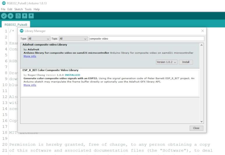
This is another feature I had originally planned as some type of configurable data. My predecessor ESP_8_BIT handled it as a compile-time flag. But just as I decided to make double-buffering run all the time in the interest of keeping the Arduino API easy to use, I’ve decided to collect performance metrics all the time. The compromise is that I only do so for users of the Adafruit GFX API, who have already chosen ease of use over maximum raw performance. The people who use the raw frame buffer API will not take the performance hit, and if they want performance metrics they can copy what I’ve done and tailor it to their application.

The key counter underlying my performance measurement code goes directly down to a feature of the Tensilica CPU. CCount, which I assume to mean cycle count, is incremented at every clock cycle. When the CPU is running at full speed of 240MHz, it increments by 240 million within each second. This is great, but the fact it is a 32-bit unsigned integer limits its scope, because that means the count will overflow every 232 / 240,000,000 = 17.895 seconds.

I started thinking of ways to keep a 64-bit performance counter in sync with the raw CCount, but in the interest of keeping things simple I abandoned that idea. I will track data through each of these ~18 second periods and, as soon as CCount overflows, I’ll throw it all out and start a new session. This will result in some loss of performance data but it eliminates a ton of bookkeeping overhead. Every time I notice an overflow, statistics from the session is output to logging INFO level. The user can also query the running percentage of the session at any time, or explicitly terminate a session and start a new one for the purpose of isolating different code.

The percentage reported is the ratio of of clock cycles spent in waitForFrame() relative to the amount of time between calls. If the drawing loop does no work, like this:

void loop() {
  videoOut.waitForFrame();
}

Then 100% of the time is spent waiting. This is unrealistic because it’s not useful. For realistic drawing loops that does more work, the percentage will be lower. This number tells us roughly how much margin we have to spare to take on more work. However, “35% wait time” does not mean 35% CPU free, because other work happens while we wait. For example, the composite video signal generation ISR is constantly running, whether we are drawing or waiting. Actual free CPU time will be somewhere lower than this reported wait percentage.

The way this percentage is reported may be unexpected, as it is an integer in the range from 0 to 10000 where each unit is a percent or a percent. The reason I did this is because the floating-point unit on an ESP32 imposes its own overhead that I wanted to avoid in my library code. If the user wants to divide by 100 for a human-friendly percentage value, that is their choice to accept the floating-point performance overhead. I just didn’t want to force it on every user of my library.

Lastly, the session statistics include frames rendered & missed, and there is an overflow concern for those values as well. The statistics will be nonsensical in the ~18 second session window where either of them overflow, though they’ll recover by the following session. Since these are unsigned 32-bit values (uint32_t) they will overflow at 232 frames. At 60 frames per second, that’s a loss of ~18 seconds of data once every 2.3 years. I decided not to worry about it and turn my attention to memory consumption instead.

[Code for this project is publicly available on GitHub]

Double Buffering Coordinated via TaskNotify

Eliminating work done for pixels that will never been seen is always a good change for efficiency. Next item on the to-do list is to work on pixels that will be seen… but we don’t want to see them until they’re ready. Version 1.0.0 of ESP_8_BIT_composite color video out library used only a single buffer, where code is drawing to the buffer at the same time the video signal generation code is reading from the buffer. When those two separate pieces of code overlap, we get visual artifacts on screen ranging from incomplete shapes to annoying flickers.

The classic solution to this is double-buffering, which the precedent ESP_8_BIT did not do. I hypothesize there were two reasons for this: #1 emulator memory requirements did not leave enough for a second buffer and #2 emulators sent its display data in horizontal line order, managing to ‘race ahead” of the video scan line and avoid artifacts. But now both of those are gone. #1 no longer applies because emulators had been cut out, freeing memory. And we lost #2 because Adafruit GFX is concentrated around vertical lines so it is orthogonal to scan line and no longer able to “race ahead” of it resulting in visual artifacts. Thus we need two buffers. A back buffer for the Adafruit GFX code to draw on, and a front buffer for the video signal generation code to read from. At the end of each NTSC frame, I have an opportunity to swap the buffers. Doing it at that point ensures we’ll never try to show a partially drawn frame.

I had originally planned to make double-buffering an optional configurable feature. But once I saw how much of an improvement this was, I decided everyone will get it all of the time. In the spirit of Arduino library style guide recommendations, I’m keeping the recommended code path easy to use. For simple Arduino apps the memory pressure would not be a problem on an ESP32. If someone wants to return to single buffer for memory needs, or maybe even as a deliberate artistic decision to have flickers, they can take my code and create their own variant.

Knowing when to swap the buffer was easy, video_isr() had a conveniently commented section // frame is done. At that point I can swap the front and back buffers if the back buffer is flagged as ready to go. My problem was that I didn’t know how to signal the drawing code they have a new back buffer and they can start drawing the next frame. The existing video_sync() (which I use for my waitForFrame() API) forecasts the amount of time to render a frame and uses vTaskDelay() which I am somewhat suspicious of. FreeRTOS documentation has the disclaimer that vTaskDelay() has no guarantee that it will resume at the specified time. The synchronization was thus inferred rather than explicit, and I wanted something that ties the two pieces of code more concretely together. My research eventually led to vTaskNotifyGiveFromISR() I can use in video_isr() to signal its counterpart ulTaskNotifyTake() which I will use for a replacement implementation of video_sync(). I anticipate this will prove to be a more reliable way for the application code to know they can start working on the next frame. But how much time do they have to spare between frames? That’s the next project: some performance metrics.

[Code for this project is publicly available on GitHub]

The Fastest Pixels Are Those We Never Draw

It’s always good to have someone else look over your work, they find things you miss. When Emily Velasco started writing code to run on my ESP_8_BIT_composite library, her experiment quickly ran into flickering problems with large circles. But that’s not as embarrassing as another problem, which triggered ESP32 Core Panic system reset.

When I started implementing a drawing API, I specified X and Y coordinates as unsigned integers. With a frame buffer 256 pixels wide and 240 pixels tall, it was a great fit for 8-bit unsigned integers. For input verification, I added a check to make sure Y did not exceed 240 and left X along as it would be a valid value by definition.

When I put Adafruit’s GFX library on top of this code, I had to implement a function with the same signature as Adafruit used. The X and Y coordinates are now 16-bit numbers, so I added a check to make sure X isn’t too large either. But these aren’t just 16-bit numbers, they are int16_t signed integers. Meaning coordinate values can be negative, and I forgot to check that. Negative coordinate values would step outside the frame buffer memory, triggering an access violation, hence the ESP32 Core Panic and system reset.

I was surprised to learn Adafruit GFX default implementation did not have any code to enforce screen coordinate limits. Or if they did, it certainly didn’t kick in before my drawPixel() override saw them. My first instinct is to clamp X and Y coordinate values within the valid range. If X is too large, I treat it as 255. If it is negative, I treat it as zero. Y is also clamped between 0 and 239 inclusive. In my overrides of drawFastHLine and drawFastVLine, I also wrote code to gracefully handle situations when their width or heights are negative, swapping coordinates around so they remain valid commands. I also used the X and Y clamping functions here to handle lines that were partially on screen.

This code to try to gracefully handle a wide combination of inputs added complexity. Which added bugs, one of which Emily found: a circle that is on the left or right edge of the screen would see its off-screen portion wrap around to the opposite edge of the screen. This bug in X coordinate clamping wasn’t too hard to chase down, but I decided the fact it even exists is silly. This is version 1.0, I can dictate the behavior I support or not support. So in the interest of keeping my code fast and lightweight, I ripped out all of that “plays nice” code.

A height or a width is negative? Forget graceful swapping, I’m just not going to draw. Something is completely off screen? Forget clamping to screen limits, stuff off-screen are just not going to get drawn. Lines that are partially on screen still need to be gracefully handled via clamping, but I discarded all of the rest. Simpler code leaves fewer places for bugs to hide. It is also far faster, because the fastest pixels are those that we never draw. These optimizations complete the easiest updates to make on individual buffers, the next improvement comes from using two buffers.

[Code for this project is publicly available on GitHub]

Overriding Adafruit GFX HLine/VLine Defaults for Performance

I had a lot of fun building a color picker for 256 colors available in the RGB332 color space, gratuitous swoopy 3D animation and all. But at the end of the day it is a tool in service of the ESP_8_BIT_composite video out library. Which has its own to-do list, and I should get to work.

The most obvious work item is to override some Adafruit GFX default implementations, starting with the ones explicitly recommended in comments. I’ve already overridden fillScreen() for blanking the screen on every frame, but there are more. The biggest potential gain is the degenerate horizontal-line drawing method drawFastHLine() because it is a great fit for ESP_8_BIT, whose frame buffer is organized as a list of horizontal lines. This means drawing a horizontal line is a single memset() which I expect to be extremely fast. In contrast, vertical lines via drawFastVLine() would still involve a loop iterating over the list of horizontal lines and won’t be as fast. However, overriding it should still gain benefit by avoiding repetitious work like validating shared parameters.

Given those facts, it is unfortunate Adafruit GFX default implementations tend to use VLine instead of the HLine that would be faster in my case. Some defaults implementations like fillRect() were easy to switch to HLine, but others like fillCircle() is more challenging. I stared at that code for a while, grumpy at lack of comments explaining what it is doing. I don’t think I understand it enough to switch to HLine so I aborted that effort.

Since VLine isn’t ESP_8_BIT_composite’s strong suit, these default implementations using VLine did not improve as much as I had hoped. Small circles drawn with fillCircle() are fine, but as the number of circles increase and/or their radius increase, we start seeing flickering artifacts on screen. It is actually a direct reflection of the algorithm, which draws the center vertical line and fills out to either side. When there is too much to work to fill a circle before the video scanlines start, we can see the failure in the form of flickering triangles on screen, caused by those two algorithms tripping over each other on the same frame buffer. Adding double buffering is on the to-do list, but before I tackle that project, I wanted to take care of another optimization: clipping off-screen renders.

[Code for this project is publicly available on GitHub]

Notes Of A Three.js Beginner: QuaternionKeyframeTrack Struggles

When I started researching how to programmatically animate object rotations in three.js, I was warned that quaternions are hard to work with and can easily bamboozle beginners. I gave it a shot anyway, and I can confirm caution is indeed warranted. Aside from my confusion between Euler angles and quaternions, I was also ignorant of how three.js keyframe track objects process their data arrays. Constructor of keyframe track objects like QuaternionKeyframeTrack accept (as their third parameter) an array of key values. I thought it would obviously be an array of quaternions like [quaterion1, quaternion2], but when I did that, my CPU utilization shot to 100% and the browser stopped responding. Using the browser debugger, I saw it was stuck in this for() loop:

class QuaternionLinearInterpolant extends Interpolant {
  constructor(parameterPositions, sampleValues, sampleSize, resultBuffer) {
    super(parameterPositions, sampleValues, sampleSize, resultBuffer);
  }
  interpolate_(i1, t0, t, t1) {
    const result = this.resultBuffer, values = this.sampleValues, stride = this.valueSize, alpha = (t - t0) / (t1 - t0);
    let offset = i1 * stride;
    for (let end = offset + stride; offset !== end; offset += 4) {
      Quaternion.slerpFlat(result, 0, values, offset - stride, values, offset, alpha);
    }
    return result;
  }
}

I only have two quaterions in my key frame values, but it is stepping through in increments of 4. So this for() loop immediately shot past end and kept looping. The fact it was stepping by four instead of by one was the key clue. This class doesn’t want an array of quaternions, it wants an array of quaternion numerical fields flattened out.

  • Wrong: [quaterion1, quaternion2]
  • Right: [quaterion1.x, quaterion1.y, quaterion1.z, quaterion1.w, quaternion2.x, quaternion2.y, quaternion2.z, quaternion2.w]

The latter can also be created via quaterion1.toArray().concat(quaternion2.toArray()).

Once I got past that hurdle, I had an animation on screen. But only half of the colors animated in the way I wanted. The other half of the colors went in the opposite direction while swerving wildly on screen. In a HSV cylinder, colors are rotated across the full range of 360 degrees. When I told them to all go to zero in the transition to a cube, the angles greater than 180 went one direction and the angles less than 180 went the opposite direction.

Having this understanding of the behavior, however, wasn’t much help in trying to get things working the way I had it in my head. I’m sure there are some amateur hour mistakes causing me grief but after several hours of ever-crazier animations, I surrendered and settled for hideous hacks. Half of the colors still behaved differently from the other half, but at least they don’t fly wildly across the screen. It is unsatisfactory but will have to suffice for now. I obviously don’t understand quaternions and need to study up before I can make this thing work the way I intended. But that’s for later, because this was originally supposed to be a side quest to the main objective: the Arduino color composite video out library I’ve released with known problems I should fix.

[Code for this project is publicly available on GitHub]

Notes Of A Three.js Beginner: Euler Angles vs. Quaternions

I was pretty happy with how quickly I was able to get a static 3D visualization on screen with the three.js library. My first project to turn the static display into an interactive color picker also went smoothly, giving me a great deal of self confidence for proceeding to the next challenge: adding an animation. And this was where three.js put me in my place reminding me I’m still only a beginner in both 3D graphics and JavaScript.

Before we get to details on how I fell flat on my face, to be fair three.js animation system is optimized for controlling animations created using content creation tools such as Blender. In this respect, it is much like Unity 3D. In both of these tools, programmatically generated animations are not the priority. In fact there weren’t any examples for me to follow in the manual. I hunted around online and found DISCOVER three.js, which proclaimed itself as “The Missing Manual for three.js”. The final chapter (so far) of this online book talks about animations. This chapter had an ominous note on animation rotations:

As we mentioned back in the chapter on transformations, quaternions are a bit harder to work with than Euler angles, so, to avoid becoming bamboozled, we’ll ignore rotations and focus on position and scale for now.

This is worrisome, because my goal is to animate the 256 colors between two color model layouts. From the current layout of a HSV cylinder, to a RGB cube. This required dealing with rotations and just as the warning predicted that’s what kicked my butt.

The first source confusion is between Euler angles and quaternions when dealing with three.js 3D object properties. Object3D.rotation is an object representing Euler angles, so trying to use QuaternionKeyframeTrack to animate object rotation resulted in a lot of runtime errors because the data types didn’t match. This problem I blame on JavaScript in general and not three.js specifically. In a strongly typed language like C there would be an error indicating I’ve confused my types. In JavaScript I only see errors at runtime, in this case one of these two:

  1. When the debug console complains “NaN error” it probably meant I’ve accidentally used Euler angles when quaternions are expected. Both of those data types have fields called x, y, and z. Quaterions have a fourth numeric field named w, while Euler angles have a string indicating order. Trying to use an Euler angle as quaternion would result in the order string trying to fit in w, which is not a number hence the NaN error.
  2. When the debug console complains “THREE.Quaternion: .setFromEuler() encountered an unknown order:” it means I’ve done the reverse and accidentally used Quaternion when Euler angles are expected. This one is fortunately a bit more obvious: numeric value w is not a string and does not dictate an order.

Getting this sorted out was annoying, but this headache was nothing compared to my next problem: using QuaternionKeyframeTrack to animate object rotations.

[Code for this project is publicly available on GitHub]

Notes Of A Three.js Beginner: Color Picker with Raycaster

I was pleasantly surprised at how easy it was to use three.js to draw 256 cubes, each representing a different color from the 8-bit RGB332 palette available for use in my composite video out library. Arranged in a cylinder representing the HSV color model, it failed to give me special insight on how to flatten it into a two-dimension color chart. But even though I didn’t get what I had originally hoped for, I thought it looked quite good. So I decided to get deeper into three.js to make this more useful. Towards the end of three.js getting started guide is a list of Useful Links pointing to additional resources, and I thought the top link Three.js Fundamentals was as good of a place to start as any. It gave me enough knowledge to navigate the rest of three.js reference documentation.

After several hours of working with it, my impression is that three.js is a very powerful but not very beginner-friendly library. I think it’s reasonable for such a library to expect that developers already know some fundamentals of 3D graphics and JavaScript. From there it felt fairly straightforward to start using tools in the library. But, and this is a BIG BUT, there is a steep drop if we should go off the expected path. The library is focused on performance, and in exchange there’s less priority on fault tolerance, graceful recovery, or even helpful debugging messages for when things go wrong. There’s not much to prevent us from shooting ourselves in the foot and we’re on our own to figure out what went wrong.

The first exercise was to turn my pretty HSV cylinder into a color picker, making it an actually useful tool for choosing colors from the RGB332 color palette. I added pointer down + pointer up listeners and if they both occurred on the same cube, I change the background color to that color and display the two-digit hexadecimal code representing that color. Changing the background allows instant comparison to every other color in the cylinder. This functionality requires the three.js Raycaster class, and the documentation example translated across to my application without much fuss, giving me confidence to tackle the next project: add the ability to switch between HSV color cylinder and RGB color cube, where I promptly fell on my face.

[Code for this project is publicly available on GitHub]

HSV Color Wheel of 256 RGB332 Colors

I have a rectangular spread of all 256 colors of the 8-bit RGB332 color cube. This satisfies the technical requirement to present all the colors possible in my composite video out library, built by bolting the Adafruit GFX library on top of video signal generation code of rossumur’s ESP_8_BIT project for ESP32. But even though it satisfies the technical requirements, it is vaguely unsatisfying because making a slice for each of four blue channel values necessarily meant separating some similar colors from each other. While Emily went to Photoshop to play with creative arrangements, I went into code.

I thought I’d look into arranging these colors in the HSV color space, which I was first exposed to via Pixelblaze I used in my Glow Flow project. HSV is good for keeping similar colors together and is typically depicted as a wheel of colors with the angles around the circle corresponding to the H or hue axis. However, that still leaves two more dimensions of values: saturation and value. We still have the general problem of three variables but only two dimensions to represent them, but again I hoped the limited set of 256 colors could be put to advantage. I tried working through the layout on paper, then a spreadsheet, but eventually decided I need to see the HSV color space plotted out as a cylinder in three dimensional space.

I briefly considered putting something together in Unity3D, since I have a bit of familiarity with it via my Bouncy Bouncy Lights project. But I thought Unity would be too heavyweight and overkill for this project, specifically because I didn’t need a built-in physics engine for this project. Building a Unity 3D project takes a good chunk of time and imposes downtime breaking my trains of thought. Ideally I can try ideas and see them instantly by pressing F5 like a web page.

Which led me to three.js, a JavaScript library for 3D graphics in a browser. The Getting Started guide walked me through creating a scene with a single cube, and I got the fast F5 refresh that I wanted. In addition to rendering, I wanted a way to look around a HSV space. I found OrbitControls in the three.js examples library, letting us manipulate the camera view using a pointer device (mouse, touchpad, etc.) and that was enough for me to get down to business.

I wrote some JavaScript to convert each of the 256 RGB values into their HSV equivalents, and from there to a HSV coordinate in three dimensions. When the color cylinder popped up on screen, I was quite disappointed to see no obvious path to flatten that to two dimensions. But even though it didn’t give me the flash of insight I sought, the layout is still interesting. I see a pattern, but it is not consistent across the whole cylinder. There’s something going on but I couldn’t immediately articulate what it is.

Independent of those curiosities, I decided the cylinder looks cool all on its own, so I’ll keep working with it to make it useful.

[Code for this project is publicly available on GitHub]

Brainstorming Ways to Showcase RGB332 Palette

It’s always good to have another set of eyes to review your work, a lesson reinforced when Emily pointed out I had forgotten not everyone would know what 8-bit RGB332 color is. This is a rather critical part of using my color composite video out Arduino library, assembled with code from rossumur’s ESP_8_BIT project and Adafruit’s GFX library. I started with the easy part of amending my library README to talk about RGB332 color and list color codes for a few common colors to get people started, but I want to give them access to the rest of the color palette as well.

Which led to the next challenge: What’s the best way to present this color palette? There is a fairly fundamental part of this challenge: there are three dimensions to a RGB color value: Red, Green, and Blue. But a chart on a web page only has two dimensions. Dictating that diagrams illustrating color spaces can only show a two-dimensional slice out of a three dimension volume.

For this challenge, being limited to just 256 colors became an advantage. It’s a small enough number that I could show all 256 colors by putting a few such slices side by side. The easiest one is to slice among the blue axis, since it only had two bits in RGB332 so there are only four slices of blue. Each slice of blue shows all combinations of the red and green channels. They had three bits each for 23 = 8 values, and combining them means 8 * 8 = 64 colors in each slice of blue. The header image for this post arranges the four blue slices side-by-side. This is a variant of my Arduino library example RGB332_pulseB which changes the blue channel over time instead of laying them out side by side.

But even though this was a complete representation of the palette, Emily and I were unsatisfied with this layout. Too many similar colors were separated by this layout. Intuitively it feels like there should be a potential arrangement for RGB332 colors that would allow similar colors to always be near each other. It wouldn’t apply in the general case, but we only have 256 colors to worry about, and that might work to our advantage again. Emily dived into Photoshop because she’s familiar with that tool, and designed some very creative approaches to the idea. I’m not as good with Photoshop, so I dived into what I’m familiar with: writing code.

My RGB332 Color Code Oversight

I felt a certain level of responsibility after my library was accepted to the Arduino library manager, and wrote down all the things I knew I could work on under GitHub issues for the project. I also filled out the README file with usage basics, and I had felt pretty confident I have enabled people to generate color composite video out signals from their ESP32 projects. This confidence was short-lived. My first guinea pig volunteer for a test drive was Emily Velasco, who I credit for instigating this quest. After she downloaded the library and ran my examples, she looked at the source code and asked a perfectly reasonable question: “Roger, what are these color codes?”

Oh. CRAP.

Having many years of experience playing in computers graphics, I was very comfortable with various color models for specifying digital image data. When I read niche jargon like “RGB332”, I immediately know it meant an 8-bit color value with most significant three bits for red channel, three bits for green, and least significant two bits for blue. I was so comfortable, in fact, that it never occurred to me that not everybody would know this. And so I forgot to say anything about it in my library documentation.

I thanked Emily for calling out my blind spot and frantically got to work. The first and most immediate task was to update the README file, starting with a link to the Wikipedia section about RGB332 color. I then followed up with a few example values, covering all the primary and secondary colors. This resulted in a list of eight colors which can also be minimally specified with just 3 bits, one for each color channel. (RGB111, if you will.)

I thought about adding some of these RGB332 values to my library as #define constants that people can use, but I didn’t know how to name and/or organize them. I don’t want to name them something completely common like #define RED because that has a high risk of colliding with a completely unrelated RED in another library. Technically speaking, the correct software architecture solution to this problem is C++ namespace. But I see no mention of namespaces in the Arduino API Style Guide and I don’t believe it is considered a simple beginner-friendly construct. Unable to decide, I chickened out and did nothing in my Arduino library source code. But that doesn’t necessarily mean we need to leave people up a creek, so Emily and I set out to build some paddles for this library.

Initial Issues With ESP_8_BIT Color Composite Video Out Library

I honestly didn’t expect my little project to be accepted into the Arduino Library Manager index on my first try, but it was. Now that it is part of the ecosystem, I feel obligated to record my mental to-do list in a format that others can reference. This lets people know that I’m aware of these shortcomings and see the direction I’ve planned to take. And if I’m lucky, maybe someone will tackle them before I do and give me a pull request. But I can’t realistically expect that, so putting them down on record would at least give me something to point to. “Yes, it’s on the to-do list.” So I wrote down the known problems in the issues section of the project.

First and foremost problem is that I don’t know if PAL code still works. I intended to preserve all the PAL functionality when I extracted the ESP_8_BIT code, but I don’t know if I successfully preserved it all. I only have a NTSC TV so I couldn’t check. And even if someone tells me PAL is broken, I wouldn’t be able to do anything about it. I’m not dedicated enough to go out and buy a PAL TV just for testing. [bootrino] helpfully tells me there are TV that understand both standards, which I didn’t know. I’m not dedicated enough to go out and get one of those TV for the task, but at least I know to keep an eye open for such things. This one really is waiting for someone to test and, if there are problems, submit a pull request.

The other problems I know I can handle. In fact, I had a draft of the next item: give the option to use caller-allocated frame buffer instead of always allocating our own. I had this in the code at one point, but it was poorly tested and I didn’t use it in any of the example sketches. The Arduino API Style Guide suggests trimming such extraneous options in the interest of keeping the API surface area simple, so I did that for version 1.0.0. I can revisit it if demand comes back in the future.

One thing I left behind in ESP_8_BIT and want to revive is a performance metric of some sort. For smooth display the developer must perform all drawing work between frames. The waitForFrame() API exists so drawing can start as soon as one frame ends, but right now there’s no way to know how much room was left before next frame begins. This will be useful as people start to probe the limits.

After performance metrics are online, that data can be used to inform the next phase: performance optimizations. The only performance override I’ve done over the default Adafruit GFX library was fillScreen() since all the examples call that immediately after waitForFrame() to clear the buffer. There are many more candidates to override, but we won’t know how much benefit they give unless we have performance metrics online.

The final item on this initial list of issues is support for double- or triple-buffering. I don’t know if I’ll ever get to it, but I wrote it down because it’s such a common thing to want in a graphics stack. This is a rather advanced usage and it consumes a lot of memory. At 61KB per buffer, the ESP32 can’t really afford many of them. At the very least this needs to come after the implementation of user-allocated buffers, because it’s going to be a game of Tetris to find enough memory in between developer code to create all these buffers and they know best how they want to structure their application.

I thought I had covered all the bases and was feeling pretty good about things… but I had a blind spot that Emily Velasco spotted immediately.

ESP_8_BIT Color Composite Video Out On Arduino Library Manager

I was really happy to have successfully combined two cool things: (1) the color composite video out code from rossumur’s ESP_8_BIT project, and (2) the Adafruit GFX graphics library for Arduino projects. As far as my research has found, this is a unique combination. Every other composite video reference I’ve found are either lower resolution and/or grayscale only. So this project could be an interesting complement to the venerable TVout library. Like all of my recent coding projects they’re publicly available on GitHub, but I thought it would have even better reach if I can package it as an Arduino library.

Creating an Arduino library was a challenge that’s been on my radar, but I never had anything I thought would be an unique contribution to the ecosystem. But now I do! I started with the tutorial for building an Arduino library with a morse code example. It set the foundation for me to understand the much more detailed Arduino library specification. Once I had the required files in place, my Arduino IDE recognized my code as an installed library on the system and I could create new sketches that pull in the library with a single #include.

One of my worries is the fact that this was a very hardware-specific library. It would run only on ESP32 running the Arduino Core and not any other hardware. Not the Teensy, not the SAMD, and definitely not the ATmega328. There are two layers to this protection: first, I add architectures=esp32 to my library.properties file. This will inform Arduino IDE to disable this library as “incompatible” when another architecture is selected. But I knew it was possible for someone to include the library and switch hardware target, and they would be mystified by the error messages that would follow. So the second layer of protection is this #ifdef I added that would cause a compiler error with a human-readable explanation.

#ifndef ARDUINO_ARCH_ESP32
#error This library requires ESP32 as it uses ESP32-specific hardware peripheral
#endif

I was pretty pleased by that library and set my eyes on the next level: What if this can be in the Arduino IDE Library Manager? This way people don’t have to find it on GitHub and download into their Arduino library directory, they can download directly from within the Arduino IDE. There is a documented procedure for submission to the Library Manager, but before I submitted, I made the changes to ensure my library conforms to the Arduino API style guide. Once everything looks like they’re lined up, I submitted my request to see what happens. I expected to receive feedback on problems I need to fix before my submission would be accepted, but it was accepted on the first try! This was a pleasant surprise, but I’ll be the first to admit there is still more work to be done.

Adapting Adafruit GFX Library to ESP_8_BIT Composite Video Output

I looked at a few candidate graphics libraries to make working with ESP_8_BIT video output frame buffer easier. LVGL offered a huge feature set for building user interfaces, but I don’t that is a good match for my goal. I could always go back to that later if I felt it would be worthwhile. FabGL was excluded because I couldn’t find documentation on how to adapt it to the code I have on hand, but it might be worth another look if I wanted to use its VGA output ability.

Examining those options made me more confident in my initial choice of Adafruit GFX Library. I think it is the best fit for what I want right now: Something easy to use by Arduino developers, with a gentle on-ramp thanks to the always-excellent documentation Adafruit posts for their stuff including the GFX Library. It also means there are a lot of existing code floating around out there for people to use and play with the ESP_8_BIT video generation code.

I started modifying my ESP_8_BIT wrapper class directly, removing the frame buffer interface, but then I changed my mind. I decided to leave the frame buffer option in place for people who are not afraid of byte manipulation. Instead, I created another class ESP_8_BIT_GFX that derives from Adafruit_GFX. This new class will be the developer-friendly class wrapper, and it will internally hold an instance of my frame buffer wrapper class.

When I started looking at what it would take to adapt Adafruit_GFX, I was surprised to see the list is super short. The most fundamental requirement is that I must implement a single pure virtual method: drawPixel(). I was up and running after calling the base constructor with width (256) and height (240) and implementing a single method. The rest of Adafruit_GFX base class has fallback implementations of every API that eventually boils down to a series of calls into drawPixel().

Everything beyond drawPixel() are icing on the cake, giving us plenty of options for performance improvements. I started small by overriding just the fillScreen() class, because I intend to use that to erase the screen between every frame and I wanted that to be fast. Due to how ESP_8_BIT organized the frame buffer into an array of pointers into horizontal lines, I can see drawFastHLine() as the next most promising thing to override. But I’ll resist that temptation for now, I need to make sure I can walk before I run.

[Code for this project is publicly available on GitHub]

Window Shopping: LVGL

I have the color composite video generation code of ESP_8_BIT repackaged into an Arduino display library, but right now the only interface is a pointer to raw frame buffer memory and that’s not going to cut it on developer-friendliness grounds. At the minimum I want to match the existing Arduino TVout library precedent, and I think Adafruit’s GFX Library is my best call, but I wanted to look around at a few other options before I commit.

I took a quick look at FabGL and decided it would not serve for my purpose, because it seemed to lack the provision for using an external output device like my code. The next candidate is LVGL, the self-proclaimed Light and Versatile Graphics Library. It is designed to run on embedded platforms therefore I was confident I could port it to the ESP32. And that was even before I found out there was an existing ESP32 port of LVGL so that’s pretty concrete proof right there.

Researching how I might adapt that to ESP_8_BIT code, I poked around the LVGL documentation and I was pleased it was organized well enough for me to quickly find what I was looking for: Display Interface section in the LVGL Porting Guide. We are already well ahead of where I was with FabGL. The documentation suggested allocating at least one working buffer for LVGL with a size at least 1/10th that of the frame buffer. The porting developer is then expected to register a flush callback to copy data from that LVGL working buffer to the actual frame buffer. I understand LVGL adopted this pattern because it needs RAM on board the microcontroller core to do its work. And since the frame buffer is usually attached to the display device, off the microcontroller memory bus, this pattern makes sense. I had hoped LVGL would be willing to work directly with the ESP_8_BIT buffer, but it doesn’t seem to be quite that friendly. Still, I can see a path to putting LVGL on top of my ESP_8_BIT code.

As a side bonus, I found an utility that could be useful even if I don’t use LVGL. The web site offers an online image converter to translate images to various formats. One format is byte arrays in multiple pixel formats, downloadable as C source code file. One of the pixel formats is the same 8-bit RGB332 color format used by ESP_8_BIT. I could use that utility to convert images and cut out the RGB332 section for pasting into my own source code. This converter is more elegant than that crude JavaScript script I wrote for my earlier cat picture test.

LVGL offers a lot of functionality to craft user interfaces for embedded devices, with a sizable library of control elements beyond the usual set of buttons and lists. If sophisticated UI were my target, LVGL would be an excellent choice. But I don’t really expect people to be building serious UI for display on an old TV via composite video, I expect people using my library to create projects that exploit the novelty of a CRT in this flat panel age. Simple drawing primitives like draw line and fill rectangle is available as part of LVGL, but they are not the focus. In fact the Drawing section of the documentation opens by telling people they don’t need to draw anything. I think the target audience of LVGL is not a good match for my intended audience.

Having taken these quick looks, I believe I will come back to FabGL if I wanted to build an ESP32 device that outputs to VGA. If I wanted to build an embedded brain for a device with a modern-looking user interface, LVGL will be something I re-evaluate seriously. However, when my goal is to put together something that will be quick and easy to play with throwing something colorful on screen over composite video, neither are a compelling choice over Adafruit GFX Library.

Window Shopping: FabGL

I have a minimally functional ESP32 Arduino display library that lets sketches use the color composite video signal generator of ESP_8_BIT to send their own graphics to an old-school tube TV. However, all I have as an interface is a pointer into the frame buffer. This is fine when we just need a frame buffer to hand to something like a video game console emulator, but that’s a bit too raw to use directly.

I need to put a more developer-friendly graphics library on top of this frame buffer, and I have a few precedents in mind. It needs to be at least as functional as the existing TVout Arduino library, which only handles monochrome but does offer a minimally functional graphics API. My prime candidate for my purpose is the Adafruit GFX Library. That is the target which contenders must exceed.

I’m willing to have an open mind about this, so I decided to start with the most basic query of “ESP32 graphics library” which pointed me to FabGL. That homepage loaded up with a list of auto-playing videos that blasted a cacophony of overlapping sound as they all started playing simultaneously. This made a terrible first impression for no technical fault of the API itself.

After I muted the tab and started reading, I saw the feature set wasn’t bad. Built specifically for the ESP32, FabGL offers some basic user interface controls, a set of drawing primitives, even a side menu of audio and input device support. On the display side (the reason I’m here) it supports multiple common display driver ICs that usually come attached to a small LCD or OLED screen. In the analog world (also the reason I’m here) it supports color VGA output though not at super high color depths.

But when I started looking for ways to adapt it to some other display mechanism, like mine, I came up empty handed. If there is provision to expose FabGL functionality on a novel new display like ESP_8_BIT color composite video generator, I couldn’t find it in the documentation. So I’ll cross FabGL off my list for that reason (not just because of those auto-playing videos) and look at something else that has well-documented ways to work on an external frame buffer.

Packaging ESP_8_BIT Video Code Into Arduino Library

I learned a lot about programming an ESP32 by poking around the ESP_8_BIT project. Some lessons were learned by hands-on doing, others by researching into documentation afterwards. And now I want to make something useful out of my time spent, cleaning up my experiments and making it easy for others to reuse. My original intent is to make it into a file people can drop into the \lib subdirectory of an PlatformIO ESP-IDF project, but I decided it could have far wider reach if I can turn it into an Arduino library.

Since users far outnumber those building Arduino libraries, majority of my web searches pointed to documentation on how to consume an Arduino library. I wanted the other end and it took a bit of digging to find documentation on how to produce an Arduino library, starting with this Morse Code example. This gave me a starting point on the proper directory structure, and what a wrapper class would look like.

I left behind a few ESP_8_BIT features during the translation to an Arduino library. The performance metric code was fairly specific to how ESP_8_BIT worked. I could bring it over wholesale but it wouldn’t be very applicable. The answer was to generalize it, but I couldn’t think of a good way to do that so I’ll leave perf metrics as a future to-do item. The other feature I left behind was the structure to run video generation on one core and the emulator on the other core. I consider ESP32 multicore programming on Arduino IDE to be an advanced topic and not my primary target audience. If someone wants to fiddle with running on another core, they’re going to need to learn about vTaskCreatePinnedToCore(). And if they’ve learned that, they know enough to launch my library wrapper class on the core of their choosing. I don’t need to do anything in my library to explicit to support it.

By working in the Arduino environment, I thought I lost access to ESP-IDF tools I grew fond of while working on Sawppy ESP32 brain. I learned I was wrong when I put in some ESP_LOGI() statements out of habit and noticed no compiler errors resulted. Cool! Looks like esp_log.h was already on the include list. That’s the good news, the bad news was that I didn’t get that log output in Arduino Serial Monitor, either. Fortunately this was easily fixed by changing an option Espressif added to the Arduino IDE “Tools” menu called “Core Debug Level“. This defaults to “None” but I can select the log level of my choosing, all the way up to maximum verbosity. If I wanted to see ESP_LOGI(), I could select level of “Info” or higher.

With this work, I built a wrapper class around the video code I extracted from ESP_8_BIT. Enough to let me manipulate the frame buffer from an Arduino sketch to put stuff on screen. But if I want to make this friendly to all Arduino developers regardless of skill level, frame buffer isn’t going to cut it. I’ll need to have a real graphics API on top of my frame buffer. And thankfully I don’t need to create one of my own from scratch, I just need to choose from the multitudes of graphics libraries already available.

ESP32 Lessons From ESP_8_BIT: CPU and Memory Allocation

I learn best when I have a working example I can poke and prod and tinker to see how it works. With Adafruit’s Uncanny Eye sort of running on my ESP32 running ESP_8_BIT code, I have a long list of things I could learn using this example as test case.

ESP32 CPU Core Allocation

Peter Barrett / rossumur of ESP_8_BIT said one of the things that made ESP_8_BIT run well were the two high performance cores available on an ESP32. Even the single-core variant only hiccups when accessing flash storage. When running on the more popular dual-core chips, core 0 handles running the emulator and core 1 handles the composite video signal generation. In esp_8_bit.ino we see the xTaskCreatePinnedToCore() call tying emulator to core 0, but I didn’t see why the Arduino default loop() was necessarily on core 1. It’s certainly an assertion backed by claims elsewhere online, but I wanted to get to the source.

Digging through Espressif’s Arduino Core for ESP32 repository, I found the key is configuration parameter ARDUINO_RUNNING_CORE. This is used to launch the task running Arduino loop() in main.cpp. It is core 1 by default, but that’s not necessarily the case. The fact it is a project configuration parameter means it could be changed, but it’s not clear when we might want to do so.

Why is core 1 the preferred core for running our code? Again the convention wisdom here says this is because the WiFi stack on an ESP32 runs on core 0. But again, this is not necessarily the case. It is in fact possible to configure the WiFi task with a different core affinity than the default, but again it’s not clear when we might want to do so. But at least now I know where to look to see if someone has switched it up, in case that becomes an important data point for debugging or just understanding a piece of code.

ESP32 Memory Allocation

I knew a Harvard architecture microcontroller like the ESP32 doesn’t have the freedom of a large pool of universally applicable memory I can allocate at will. I remember I lost ability to run ESP_8_BIT in Atari mode due to a memory allocation issue, so I went back and re-read the documentation on ESP32 memory allocation. There is a lot of information in that section, and this wasn’t the first time I read it. Every time I do, I understand a little more.

My Atari emulator failure was its inability to get a large contiguous block of memory. For the best chances of getting this memory, the MALLOC() allocator specified 32-bit accessible memory. This would open up areas that would otherwise be unavailable. But even with this mechanism, the Atari allocation failed. There are tools available to diagnose heap memory allocation problems and while it might be instructive to understand exactly why Atari emulator failed, I decided that’s not my top priority right now because I’m not using the Atari path.

I thought it was more important to better understand the video generation code, which I am using. I noticed methods in the video generation code were marked with IRAM_ATTR and thought it was important to learn what that meant. I learned IRAM_ATTR marked these as pieces of code that needs to stay in instruction RAM and not optimized out to flash memory. This is necessary for interrupt service routines registered with ESP_INTR_FLAG_IRAM.

But those are just the instructions, how about the data those pieces of code need? That’s the corresponding DRAM_ATTR and I believe I need to add them to the palette tables. They are part of video generation, and they are constant unchanging values that the compiler/linker might be tempted to toss out to flash. But they must no be moved out because the video generation routine (including ISRs) need to access them, and if they are not immediately available in memory everything comes crashing down.

With these new nuggets of information now in my brain, I think I should try to turn this particular ESP32 adventure into something that would be useful to others.

Putting Adafruit Uncanny Eyes on a Tube TV

I have extracted the NTSC color composite video generation code from rossumur’s ESP_8_BIT project, and tested it by showing a static image. The obvious next step is to put something on screen that moves, and my test case is Adafruit’s Uncanny Eyes sketch. This is a nifty little display I encountered on Adafruit’s Hallowing and used in a few projects since. But even though I’ve taken a peek at the code, I’ve yet to try running that code on a different piece of hardware as I’m doing now.

Originally written for a Teensy 3 and a particular display, Uncanny Eyes has grown to support more microcontrollers and display modules including those on the Hallowing. It is now quite a complicated beast, littered with #ifdef sections blocking out code to support one component or another. It shows all the evidence of a project that has grown too unwieldy to easily evolve, which is probably why Adafruit has split into separate repositories for more advanced versions. There’s one for Cortex-M4, another one for Raspberry Pi, and possibly others I haven’t seen. In classic and admirable Adafruit fashion, all of these have corresponding detailed guides. Here’s the page for the Cortex-M4 eyes, here’s the page for Pi Eyes, in addition to the Teensy/Hallowing M0 eyes that got me started on this path.

If my intent was to put together the best version I can on a TV, I would study all three variants. Read Adafruit documentation and review the code. But my intent is a quick proof of concept, so I pulled down the M0 version I was already familiar with from earlier study and started merrily hacking away. My objective was putting a moving eye on screen, and the key drawEye() method was easily adapted to write directly to my _lines frame buffer. This allowed me to cut out all code talking to a screen over SPI and such. This code had provisions for external interactivity such a joystick for controlling gaze direction, a button for blink, and a light sensor to adjust iris. I wanted a standalone demo and didn’t care about that, and thankfully the code had provisions for a standalone demo. All I had to do was make sure a few things were #define (or not #define)-ed. That left a few places that were inconvenient to configure purely from #define, so I deleted them entirely for the purpose of the demo. They’ll have to be fixed before interactivity can be restored in this code.

The code changes I had to make to enable this proof of concept is visible in this GitHub commit. It successfully put a moving eye on my tube TV on my ESP32 using a composite video cable, running the color NTSC composite video generation code I pulled out of rossumur’s ESP_8_BIT project. With the concept proven, I don’t intend to polish or refine it. This was just a crude test run to see if these two pieces would work together. I set this project aside and moved on to other lessons I wanted to learn.

[Code for this project is publicly available on GitHub]

Extracting ESP_8_BIT Sega Color Video

ESP_8_BIT implemented a system that could run one of three classic video game console emulators on an ESP32, but my interest is not in those games. My objective is to extract its capability to generate and output a NTSC composite video signal, and significantly, doing it in color without hardware modification. I chose the Sega emulator video generation code path for my project, since it had better color than the Nintendo emulator code path. The Atari emulator code path was not a candidate as it had stopped working on my ESP32 for memory allocation failures, caused by factors I don’t understand and might investigate later.

The objective of today’s project will mean deleting the majority of ESP_8_BIT. Most of the bulk were cut away quickly when I removed all three emulation engines along with their game ROMs. All three emulation engines had an adapter class that derived from a base emulator (Emu) class, and they were removed without issue thanks to the clean architecture separation. All lower level code interact with the emulators via the base class. With so many references to the base class sprinkled throughout the code, it took more finesse to find and cleanly remove them all.

Beyond the color video generation code that is my objective, there were various other system level services that I wanted to strip off to get to a minimum functional baseline. My first few projects will go without any of the following functionality: Bluetooth controller interface, infrared (IR) remote interface, and loading ROMs from on-board SPIFFS storage of ESP32. These are all fairly independent subsystems. Once I have built confidence in the base video code, and if I should need any of the other system services, I can add them back in one at a time.

That leaves a few items intertwined with video output routines. The easiest to remove were the portions specific to Atari and Nintendo emulators, clearly marked off with #ifdef statements. ESP_8_BIT creator rossumur explained that the color signal hack had an unfortunate side effect of interfering with standard ESP32 audio output peripherals, so as an alternate mechanism audio had to be generated via ESP32’s LEDC peripheral originally designed for controlling LED illumination. Since audio didn’t seem to work on my setup anyway, I removed that mechanism as well. The final bit of functionality I didn’t need was PAL support since I didn’t have a PAL TV. I started removing that code but changed my mind. The work to keep PAL looks to be fairly manageable, and it’s definitely a part of video signal generation. Plus, I want this project to be accessible to people with PAL screens. However, I have to remember to document the fact that I don’t have a PAL TV to test against, so if I inadvertently break PAL support with this work I wouldn’t know unless someone else tells me.

Another reason for choosing the Sega emulator code path is that its color palette is a mapping I know as RGB332. It is a way to encode color in eight bits: three bits for red, three for green, and two for blue. This mapping is more common than hardware-specific palettes of either Atari or Nintendo paths. I anticipate using RGB332 will make future projects much easier to manage.

As a practice run of the code that’s left after my surgery, I wrote a test to load a color image. The was a picture Emily took of her cat, cropped to 4:3 aspect ratio of old school tube TVs and then scaled to the 256×240 resolution of the target frame buffer. This results in a PNG file that looks vertically stretched due to the non-square pixels. Then I had to convert the image to RGB332 color. Since this is just a practice run, I wrote a quick script to extract the most significant bits in each color channel. This is an extremely crude way to downconvert image color lacking nice features like dithering. But image quality is not a high concern here, I just wanted to see a recognizable cat on screen. And I did! This successful static image test leads to the next test: put something on screen that moves.

[Result of this extraction project is publicly available on GitHub]

Observations on ESP_8_BIT Nintendo and Sega Colors

I have only scratched the surface of rossumur’s ESP_8_BIT project, but I got far enough for a quick test. I rendered the color palette available while in Nintendo emulation mode, and found that it roughly tracks with the palette shown on its corresponding Wikipedia page.

I say “roughly” because the colors seem a lot less vibrant than I would have expected from a video game. These colors are more pastel, or maybe like a watercolor painting. For whatever reason the color saturation wasn’t as high as I had expected. But judging color is a tricky thing, our vision system is not a precision instrument. What I needed was a reference point, and I found one with the OSD (on-screen display) for this TV’s menu system.

This menu is fairly primitive, using basic colors at full saturation. I can see the brilliant red I expected for Mario, alongside the brilliant green I expected for Luigi. These colors are more vibrant than what I got out of the Nintendo emulator palette. What causes this? I have no idea. NTSC colorburst math is voodoo magic to me, and rossumur’s description of how ESP_8_BIT performs it went high over my head. For the moment I choose to not worry about the saturation. I am thankful that I have colors at all as it is a far superior situation than earlier grayscale options.

At this point I felt confident enough to look at the Sega emulator code path, and was encouraged to see the table returned by its ntsc_palette() method had 256 entries instead of the 64 in the Nintendo path. Switching ESP_8_BIT into Sega mode, I can see a wider range of colors.

Not only are there four times the number of colors available, some of the saturation looks pretty good, too.

The red (partially truncated by overscan in the lower left) is much closer to the red seen on OSD, the yellow and blue looks pretty good, too. The green is still a bit weak, but I like what I see here. With its wider range of colors in its palette, I decided to focus on ESP_8_BIT Sega emulator code path from this point onwards.