Documenting Glow Flow Online

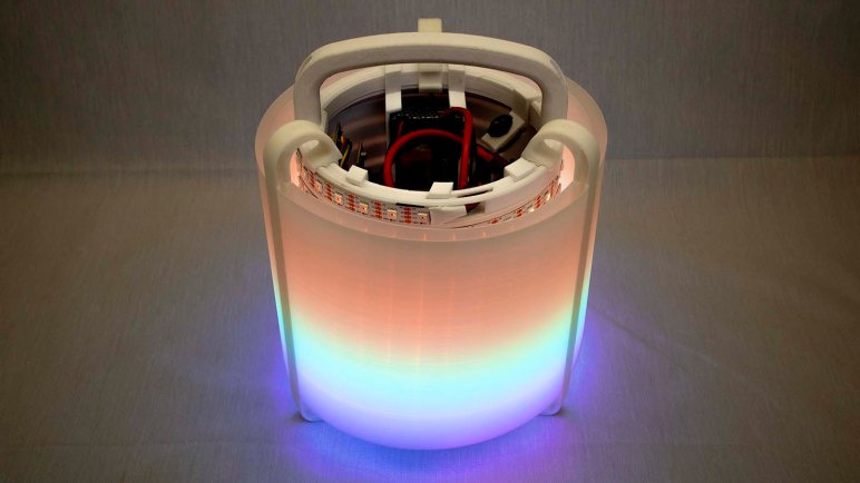
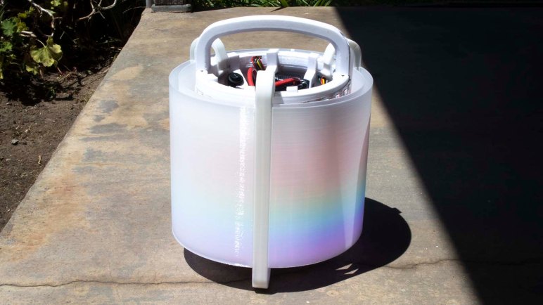
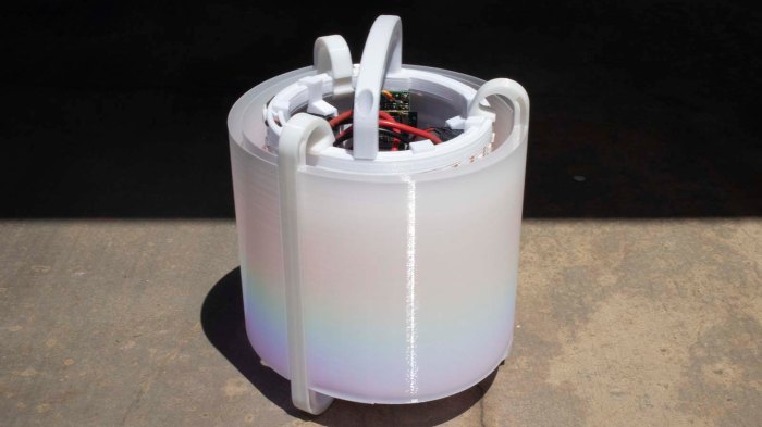
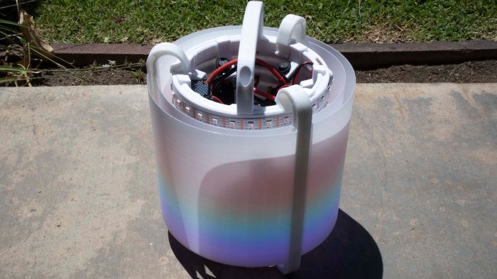
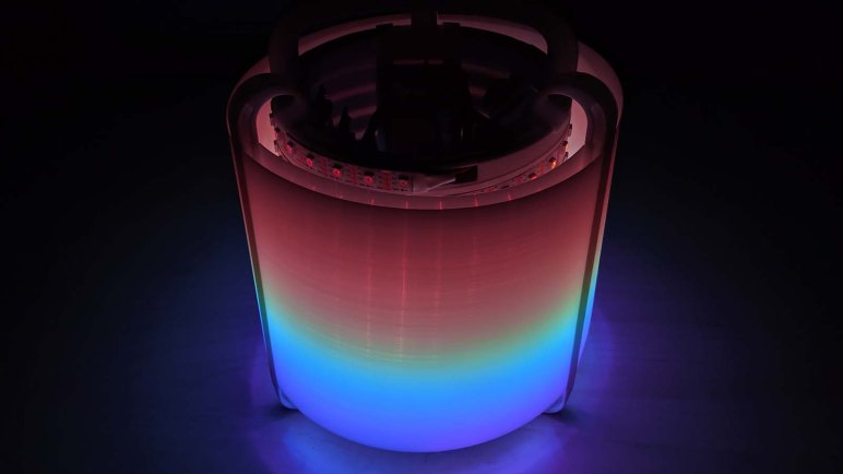
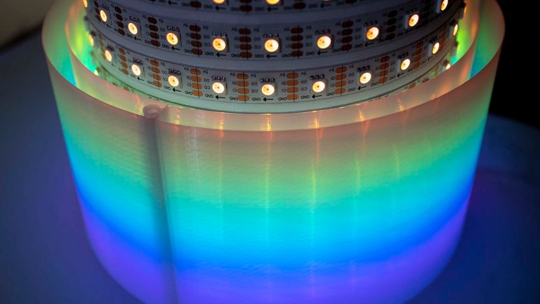
My Pixelblaze (and its sensor board) demonstration project Glow Flow is now complete. Well, maybe not “complete” but I’ve decided to stop here instead of exploring other ideas to continue evolving project. For now I’ll keep Glow Flow as-is, but before I shift attention to other projects, I should finish documenting this one before I forget everything.

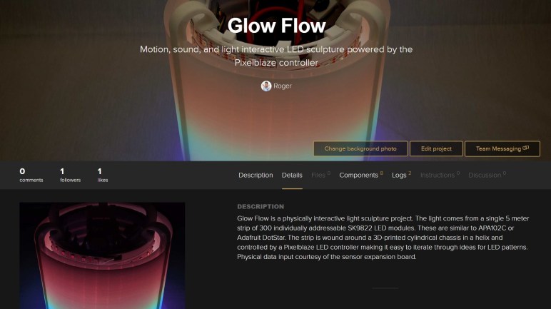
First thing to do is to create a Hackaday.io project page, with links to all the other resources. Then I gathered all the video I’ve shot through the project and edited them all together into a YouTube video. (Embedded below.) I personally prefer to read about projects, but I acknowledge that some prefer video and I want them to enjoy Glow Flow as well.

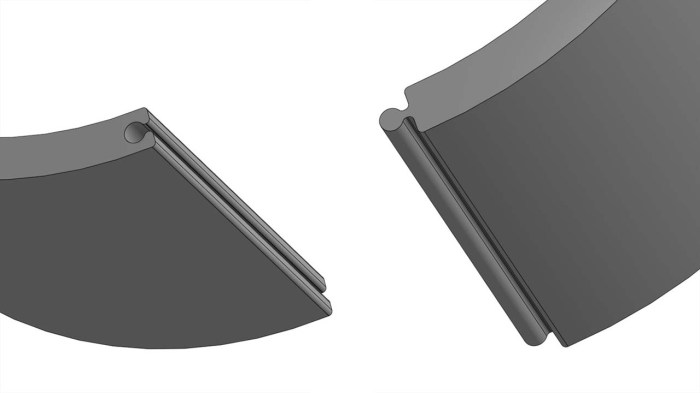
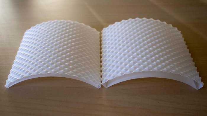
The Github repository where I had been tracking my Pixelblaze pattern code revisions also got an updated README.md. So anyone who encounters the project on Github will have links to all the other resources I’ve put online. And like every other file I’ve created on the free tier of Onshape, Glow Flow CAD data is publicly available too.

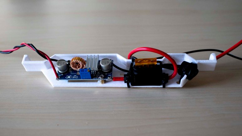
As an experiment I put Glow Flow on Hackster.io as well. It’s not terribly different from a Hackaday.io project page, with one notable exception: I’m expected to upload a schematic for a project before publishing it. This meant I had to fire up KiCad and re-learn its schematic editor to create a rudimentary schematic detailing how Glow Flow electronics components are connected. I didn’t think it was a very sophisticated circuit, but my judgement is not to be trusted as everything is still fresh in my mind. Chances are good I’ll forget details in the future and appreciate the schematic is available. I’ve also uploaded the schematic to the Github repo so it is saved in at least two different places.

This should be enough information for someone (including future me) to understand and build another Glow Flow if they so desire.

Glow Flow Project Complete

With an upgraded power system, Glow Flow can now run continuously at full brightness. This completes Glow Flow as a self-contained portable demonstration of Pixelblaze LED controller. I plan to leave it in this configuration for the foreseeable future, but the flexibility of Pixelblaze and the 3D-printed snap-together construction means it’d be easy to reuse the core components for another project in the future. The Pixelblaze is in no shortage of storage space for other patterns, and the LED strip wound around a cylindrical core can easily accept a different external “sleeve” tailored to a different design.

People have suggested some other visual patterns, some would work better with different LED diffuser exterior:

  • Illusion of a lantern, complete with a flickering flame inside.
  • Illusion of a fish tank, with colorful fishes swimming inside.
  • Glowing lava, matching my original plan.
  • Animated Jack-o-Lantern for Halloween.
  • Glowing green like a bucket of radioactive slime.
  • Glowing purple/pink like the Energon Cubes in Transformers cartoons. Of course, they’re supposed to be cubes and not cylinders.

Any of those are within the means of a Pixelblaze, but depending on specifics of a pattern, power requirements may different. Dramatically increased power draw would demand an upgraded power system as well, something to keep in mind.

There were two fascinating ideas to improve interactivity:

  1. Make colors flow past each other as in a lava lamp. This is similar to earlier suggestions of making different color pixels swirl and mix. This requires a substantial investigation into how to run a computational fluid dynamics simulation in a Pixelblaze pattern. I’m currently ignorant on CFD math so that will be a significant undertaking.
  2. Make the diffuser touch-sensitive so the illuminated pattern on LED cylinder can react to user touch. This is a significant upgrade to interactivity than merely reading an accelerometer. Experimentation with simple touch sensors imply smaller touch area is better. It would be challenging to make the entire exterior surface of the cylinder touch-sensitive, but the results would be worth the effort.

These are all great ideas for a future interactive LED project. When I’m bored with Glow Flow, I’ll remove the diffuser panel and their support ribs. Extract the core cylinder and do something else. It would still be a Pixelblaze project, but it would no longer be Glow Flow.

For now, I’ll keep the illusion of glowing liquid flowing inside a cylinder.

Glow Flow At Full Power

Once Glow Flow was armed with dual independent power supplies, each capable of delivering 25W of power, I was confident we can unleash the full power of this fully operational interactive LED sculpture. The Pixelblaze strip settings menu setting for maximum brightness was pushed all the way up to 100%, which the pattern code will happily use if the light sensor reads full brightness.

Modern LEDs are pretty bright, and these SK9822 are clones of the APA102C is know for an extreme range of control from dim to eye-blindingly bright. What’s the brightest thing I would hope for an LED creation? I would want it to be visible in broad daylight, so out into a bright sunny Southern California summer we go.

The verdict: a very admirable effort, but these LEDs are still overpowered by the sun.

Glow Flow outdoors - sun side

Looking on the brightly lit sun side, we can barely detect some of the LED colors. The fact that it is detectable at all is a tremendous accomplishment. Most of my other LED projects are simply invisible under a full early afternoon sun! In contrast these LEDs are still visibly illuminated under these circumstances behind the diffusers. Perhaps a diffuser held closer to the LEDs, possibly with a single layer, would be visible under direct sunlight. But it would not blend light as well as the current diffusers do, and I definitely prefer the blend.

Glow Flow outdoors - shade side

On the shady side, we could see more LED power shining through. Some bare LEDs are visible from this picture angle, and they are visible under these light circumstances.

It would have been impressive if Glow Flow worked under full sunlight, but our ball of burning gas at the middle of our solar system is still the more powerful light source. Still, this is more than enough power for Glow Flow to shine in any other scenario, and I’ll call it done here.

Glow Flow Power Regulator

Early on in this project I took a brief look at power requirements for a LED strip with 300 modules. I knew my project would not require maximum power but I didn’t know exactly how much until I got further in the project. Now that I’ve measured actual power consumption with it up and running, it’s time to put a new solution together.

The first and most important thing is safety, so I will have a fuse which is commonly neglected in one-off hobbyist projects. I’ll be using batteries which are rated to supply up to 150A. Nothing in Glow Flow can withstand that power in the event of a problem or a mistake. If that should happen, something will blow, might as well be a fuse whose job it is to do so.

The second thing is the regulator module. I have MP1584 modules (*) that can deliver 2A and peak of 3A, and I have XL4015E1 modules (*) that could deliver peaks of 5A. I know Glow Flow at full brightness will demand at least 5A, with peaks of power draw beyond that when responding to sound stimulus. So the plan is to use two XL4015E1 modules, one for each half of the LED strip.

Glow Flow power module installed

And finally, the convenience of a power switch so I would not have to disconnect and reconnect the battery all the time. All components were placed on a single tray that clips to the inside of Glow Flow cylinder. Leaving plenty of room for a second identical set of battery + power regulator board.

If I had a dual-pole switch I would use one to control my two parallel power supplies. But in my parts collection of compact power switches, I only had single-pole single-throw switches. So Glow Flow will have a switch for each of its two electrically independent power systems. Flipping two switches every time is not ideal, but not the end of the world. It’s only a slight annoyance for the capacity to finally run Glow Flow at full power.


(*) Disclosure: As an Amazon Associate I earn from qualifying purchases.

Glow Flow Battery Tray

I now have some target numbers for designing a new power system for Glow Flow, and whatever system I design will need a big battery to enable long run times. The most capable batteries on hand (*) are those I purchased for Sawppy rover. These batteries are designed to deliver high amperage (~150A) by trading off raw capacity. They are not ideal batteries for Glow Flow, which would draw low amperage over a longer duration, but they’ll work and they’re already here.

I started designing the battery tray first because it is a simpler problem to solve as I start figuring out how to apply tool-less construction techniques for components inside the cylinder core. They will be clipped to the grooves in top and bottom end pieces. Batteries are also expected to be the largest and bulkiest component, so installing one will help me gauge how much volume remains to work with. Glow Flow battery clip assembled

A velcro strap holds the two pieces of this battery tray together. This strap was a free gift the battery manufacturer conveniently packaged alongside the battery.

Glow Flow battery clip installed

Previously the USB power bank was held in the center of the cylinder. This time around the battery is held against the inner side surface of Glow Flow core cylinder, leaving a few millimeters of space behind for wire routing. There appears to be plenty of space left for additional components. Next up: the power regulator board.


(*) Disclosure: As an Amazon Associate I earn from qualifying purchases.

Quantifying Glow Flow Power Consumption

Glow Flow’s LED diffuser panels completed work on its external appearance, now it is time to upgrade innards. For testing Glow Flow concept and developing associated Pixelblaze pattern code, it ran from a USB power bank.  Which had always intended to be a placeholder because it was not powerful enough to run LEDs at full brightness. The 3D-printed pieces holding that USB power bank were discarded when I moved to tool-less construction, and now I need to build a replacement portable power system for Glow Flow.

It won’t need worst case scenario amount of 90 Watts of power, as that only occurs when every LED (red, green, and blue) in every one of 300 SK9822 LED module is running at full brightness drawing 20mA each. Glow Flow would only ever demand a subset of that, because a colorful display uses less power than full white and the “upper half” of pixels are always partially illuminated to show a fade to black. But how big is the subset? With the code now running I could get some real world numbers.

The USB power bank is advertised to deliver 2A on one port and 1A on the second. This combined to 5 volts * 3 amps = 15 watts. I used Pixelblaze’s LED strip settings menu to limit maximum power to 40%. This was experimentally determined by pushing it gradually higher until the USB power bank shut itself down at around 45%.

To get a better idea of where the maximum is, Glow Flow was connected to a bench power supply set to 5V and up to the power supply unit’s maximum of 4A. When the amperage limit is reached is reached, it will reduce voltage instead of cutting out entirely like the USB power bank did.

Once connected, I returned to the Pixelblaze UI. I first edited my program to act as if the ambient light sensor is at its brightest. Then I went to the “Strip Setttings” menu and gradually increased the cap from 40% while observing power supply display. Glow Flow reached that 4A maximum (and voltage started dropping) at roughly 80% of full brightness.

I don’t have a precision instrument capable of more power, but this is enough to imply a minimum power requirement of 5A @ 5V = 25W to drive Glow Flow. And to be safe, some margin on top of that to handle brief bursts of additional power draw. I already batteries which can easily deliver the required amount of power, they just need a bracket to be mounted on board Glow Flow.

Glow Flow Diffuser Assembly Complete

Even with the help of a few test pieces, it was not a surprise that the first full sized prints of a Glow Flow flexible diffuser panel and associated rigid support rib still required a few final adjustments. But once done, I printed out a set of three ribs, three panels, and assembled them together. Each of the ribs also function as one leg of a tripod for supporting Glow Flow. Not as subtle as the previous iteration, but the same general idea.

The completed assembly was more rigid than I had anticipated. The ribs worked well and, when supported by ribs on either side, the panels could actually take some stress. Enough to allow someone to handle Glow Flow by grabbing the sides without risk of everything falling apart. This is a pleasant surprise. I started with the minimum of 3 ribs 120 degrees apart, just to see how well it worked before I increase the number of ribs. Apparently 3 ribs are sufficient so we can stop here.

But the most important part is to see how well it does its primary job of diffusing LED lights and it’s very satisfying to see that job done well.

This design has a few issues: Because of its flexible snap-together nature, the ribs are free to slide out of position no longer exactly 120 degrees from each other. When this happens some panels will bulge out more than others. A related but different problem is the panel vertically shifting within their slot. I cut the slot taller than a panel needs to be as a provision for some sort of top & bottom border pieces. But right now those slots mean a panel has room to shift, which could also result in an unsightly bulge.

Those are problems I could tackle later. For now, attention turns to restoring Glow Flow to battery-powered portable operation.

Glow Flow Diffuser Assembly Test Pieces

Limited by my 3D printer’s usable print volume, the 3D-printed thin translucent diffuser panels for Glow Flow must be printed in multiple pieces and joined together with rigid support ribs. When I experimented with snap-together construction for thin panels, I tested a simple design for joining two of these panels together. However, I’ve since found that design could not be used to join a thin diffuser panel to a rigid rib. I will need a different design better suited for the task.

The characteristics for this problem were:

  • It needs to join two parts, one rigid (support rib) and one flexible (diffuser panel)
  • Flexible portion will be printed vertically in vase mode as part of the diffuser.
  • Rigid portion will be printed printing horizontally as part of the rib.
  • No supports as I don’t want to cleaning up supports inside the slot!
  • Rigid portion must be printable both right side up or upside down so a rib can accommodate a panel on both sides.
  • The joint does not need to be equally strong in both directions. These panels are more likely to experience inward force as when someone is grabbing and handling Glow Flow by the panels. In contrast, outward force is far less likely.

To test these constraints, I printed small samples to see how small tweaks to geometry impacted performance. Each of these small samples consisted of two symmetric pieces. A rigid one representing the rib, printed the way a rib would. Plus a flexible one representing the diffuser, printed in vase mode.

Getting the pieces to fit correctly were a challenge. If the pieces are too loose, a diffuser panel might pop out at inconvenient times. If the pieces are too tight, I would not be able to insert them. The rib section is designed to be symmetric, but the center of the rib depends on 3D printer’s bridging capabilities to work without supports. A bridged surface isn’t as smooth, so there’s some asymmetry between the two slots. There’s also some asymmetry introduced by the interface with the heated print bed also sometimes called “Elephant’s Foot“. And finally, there are imperfections introduced by the 3D printer that cause parts to collide because the two pieces are printed in different orientations. Test sample #1 in the picture above shows print bed orientation of each piece.

These test pieces were useful to explore both CAD dimensions and 3D printer settings before returning to the challenge of building actual pieces for Glow Flow.

Glow Flow Diffuser Rib

3D printed in vase mode, Glow Flow diffuser panels can be held together without tools using flexible tabs. However, keeping them thin to be translucent also means they are very soft and could not hold their own weight. They will need support structures to hold them at correct distance from LEDs. At the very minimum we’ll need 3 support ribs, spaced 120 degrees apart, to support panels small enough to be printed. This first pass will install three ribs and associated panels. Once they’re up and running, we’ll evaluate the results for future iteration.

The diffuser panels re-awakened an interest in designing for tool-less construction, individual pieces that snap together. So the diffuser support rib is designed to be printed in one single piece and, through flexibility of plastic, clips onto grooves in the new top and bottom end pieces. The cross-section of this rib is an I-beam, with slots on either side for installing diffuser panels. However, the first iteration did not fit.

Glow flow diffuser rib v1 does not fit

Even though all dimensions matched the earlier diffuser panel tests, it didn’t work here because the new rib is rigid and its slots did not flex. This design only worked if both ends are flexible to accommodate each other on insertion, as was the case earlier when I had two flexible diffuser pieces fitting in each other. Now, the rib is rigid and the diffuser panel tab could not compress enough to fit within the slot. In order to proceed, I will need to put time into designing a better mechanism.

Glow Flow Core Grooved End Pieces

Once I started thinking about building my diffuser panels to snap together without fasteners, I started thinking about designing other parts of Glow Flow for tool-less construction. It is appealing to be able to perform field repairs without requiring access to a tool box. I’ve done a few other projects with this kind of thinking in mind, like the panning camera base for my Supercon 2017 badge hack. But as I started incorporating aluminum extrusions for my projects (Luggable PC both Mark I and II, and Sawppy rover) I had to use fasteners for those larger and heavier projects.

In terms of size and weight, Glow Flow sat in between those extremes, so would be a fun new frontier to explore tool-less snap together construction. The project did not start with that in mind, so my central LED cylinder core was printed with holes for M3 screws. But that is no barrier, as the cylinder was always intended to allow exploring different end pieces top and bottom without having to reprint the large core cylinder, a flexibility that I shall now take advantage of because there’s little to lose.

My current top and bottom end pieces were designed to support a USB power bank, which could not deliver enough power to run the 300 LEDs at full power. So it was never intended to be the permanent solution and those pieces were slated to be replaced eventually. I would have to find another home for the Pixelblaze circuit board, but that is a minor thing.

Replacement top and bottom end pieces were drawn up and printed, each with a central groove for modules to grip on to. They are fastened to the core cylinder using its existing provision of M3 screws but, if all goes well, there would be very few other fasteners on Glow Flow.

With removal of the USB battery bank, Glow Flow is no longer portable and is tied to my bench power supply until a new power solution is online. That is a problem to be solved later. In the near term, attention returns to the LED diffusers which had awakened my interest in designing for snap-together construction.

Glow Flow: Snap-Together LED Diffuser Panels

After exploring a few ways to make 3D-printed diffusers for Glow Flow, I decided to proceed with no surface features and instead relying on raw distance to obtain diffusion. Not putting in surface features is easy, but how would I go about keeping these panels at a distance from LEDs?

If they could have been close to the LEDs and thin, there was a chance I could print one continuous cylinder to put around these lights. But the ambition to hold them 1 cm away, and have two layers 1 cm apart, pushed overall size beyond what my printer volume could handle. I will need to move to a multi-piece system.

Going multi-piece means I have to start thinking about how the pieces would join together. And given the nature of the diffuser, anything I do will be clearly visible and backlit by Glow Flow LEDs. This makes aesthetics of the solution a much larger concern. I didn’t want to have a row of screws or really any fasteners, so I started thinking about minimalist snap-together joints for these diffuser panels.

Diffuser tab MF

The first experiment seemed to work well, these pieces They fit together with a satisfying click and held up well to moderate mechanical stress. The resulting seam is visible as a plain shadow without details to distract. No black circular shadows of fasteners. The downside is that these panels are not nearly strong enough to support themselves. I’ll have to add some rigid support ribs to hold them up. And since these panels got my mind going on tool-less construction, I’m going to continue on that theme.

Glow Flow LED Diffusion Test: Layer Separation

After playing with the magnitude of a diamond pattern as LED diffuser for Glow Flow, it looked like the easiest thing to do for a good blend is put more distance between the LEDs and their diffuser. Which led to the next question: where should that distance be? Because these diffusers were printed in vase mode, they actually have two surfaces to help with diffusion: an inner layer and an outer layer. It looks like the outer layer needs to be about 2cm away from the LEDs, but where should the inner layer be?

Glow Flow diamond wall distance no LED

If we put the inner layer close to the LEDs, it would get first stab at diffusing light early, hopefully increasing its impact on outer layer diffusion. If we put the inner layer further away, it would receive a more diffuse input to begin with. Which would end up looking better?

To test which of the two might be better, a quick test was printed up with two different separation distances between inner and outer layers. Putting them up against Glow Flow LED core, the winner was… neither. It was basically a tie.

When we held the outer layer at the same distance from LEDs, visual output is nearly indistinguishable up close. From further away, they were identical. It appears for this 3D printed diffuser approach, the position of inner layer does not matter. It is the position of outer layer that will determine diffusion.

Based on these experiments with 3D printed diffusers, neither a surface texture nor texture magnitude nor layer separation made a significant improvement in appearance. The variable with most impact is distance of outer surface from LEDs.

In commercial product development, devoting such distance for diffusers is problematic because that is empty space not productive for whatever the product is supposed to do. One example: LED taillights in cars have a very limited space budget, because any volume consumed for good diffusion means less trunk space.

But for a hobbyist project like Glow Flow, where the whole point is appearance, we can freely devote volume to allow LED diffusion with a simple 3D printed mechanism. The next step is to think about how this diffuser will be installed.

Glow Flow LED Diffusion Test: Diamond Height

Using a diamond pattern to diffuse LED light for my Glow Project had interesting results but the first iteration wasn’t quite to my liking. But it showed enough promise that I thought maybe it’ll just be a matter of tuning. The first parameter for experimentation was the magnitude of diamond peaks, how does it look to have a subtle diamond pattern versus a strong one?

Glow Flow diamond magnitude no LED

Holding them up close to the LED, the subtle pattern was preferred. A strong diamond pattern added itself into the conversation and, while that’s a valid approach to a project, it’s not the goal for this specific one.

Glow Flow diamond magnitude distant

This difference only got more pronounced as they were moved further away from the bank of LEDs. A strong diamond pattern started shouting its presence where the subtle one stayed quiet.

So far the best blending effects were accomplished just by holding the diffuser further away from the LEDs, and exterior pattern structure doesn’t do enough to mitigate the bright points of LED. But there’s another variable we can play with: these are vase prints, with an inner and outer wall. If we changed the distance between these walls, would that make a difference in distance required for a good diffusion?

Glow Flow LED Diffusion Test: Diamonds

Experiment continues to create a LED diffuser for my Glow Flow project. I started cheap with some paper towels from the kitchen, moved on to a featureless 3D printed sheet, which I then added horizontal ribs for strength. The downside of 3D printed diffusers are their layers, which interact with light resulting in uneven brightness across layers.

After observing this behavior, I decided to try using a diamond pattern overlaid at 45 degrees to printed layers. The hope is that, by changing how layers stack on top of each other, I can break up the vertical streaks of brightness. Doing this experiment meant taking my horizontal rib and, instead of revolving around a center axis, I would loft it along two helical path instead. One helix goes up, the other goes down, and the intersection of those two gave me the diamond pattern I wanted. This turned out to be a nontrivial shape to compute in Onshape CAD. I could probably do it more efficiently, but this is good enough for my experiment.

Glow flow diamond

Once printed, I held it up to Glow Flow and… well, not a complete success. The diamond pattern succeeded in breaking up the pattern of vertical glare, but just by its nature it also introduced other distortions. When Glow Flow is turned off, the diamonds introduce a pretty pattern of light and shadow relative to ambient light. But with Glow Flow turned on, that pattern also interacted with light emitted by LEDs and the results are not to my liking.

Glow Flow diamond distant

When we pull the sheets further from LEDs, the diamond pattern becomes just a distraction no better than the featureless sheet.

There’s potential here, perhaps it just requires some tuning. Let me experiment with a few variables starting with diamond surface height.

Glow Flow LED Diffusion Test: Horizontal Ribs

A 3D-printed curved sheet of plastic showed promise as LED diffusion layer, but it was very flexible and I worry about its suitability to be the outermost layer of Glow Flow. The flexibility means people who try to handle Glow Flow by grabbing this outside layer may damage the sheet, and the flexibility also means it might be difficult to control its distance and therefore diffusion.

Glow flow horizontal ribs

As an experiment to increase rigidity, the next print added a wave texture to the outer surface, giving it appearance of horizontal ribs. This shape should resist bending more than a texture-free sheet of plastic. It would also diffuse light differently, which may or may not look better. At the very least it is worth exploring and a vase mode print is a quick experiment to find out.

On the front of structural strength, the ribbed version is indeed noticeably more rigid than the featureless sheet. It still doesn’t feel rigid enough to withstand handling, but enough that I think it can maintain a particular distance (and therefore diffusion) without worry. Certainly good enough to be worth further experimentation down the line.

Ribbed versus flat distant

On the topic of visual appearance, the varying angles of these ribs picked up light from both above and below, presenting a blending of lights that correspond to the ribs themselves. On the downside, the print layer direction seems to magnify a problem where the light is focused into a vertical line that is extremely visible from certain angles. The featureless sheet also had this problem but not as serious.

The ribbed sheet is more interesting than a featureless sheet, and this opens the door to additional experiments on how we might use physical strengthening geometry to aid diffusion. The next experiment: introduce bending along more than one axis for a diamond-like pattern.

Glow Flow LED Diffusion Test: 3D Printed Sheet

Experimenting with different ways I could implement a light diffuser, there’s no reason to overlook 3D printed plastic. One problem is that 3D printed structure typically has infill that is never seen, so their placement aren’t calculated with the goal of controlling light transmitted through the structure. There are some fancy tricks we could use to control infill pattern, but the easy way out is to skip infill entirely and use a hollow plastic structure.

The other potential problem is the Z-axis seam. A fused-deposition modeling 3D printer (most popular affordable hobbyist 3D printers) puts down plastic one layer at a time. When it shifts from one layer to the next, there is a brief pause that also manifests as a little bump in plastic. Good slicers will bury this somewhere invisible, either inside infill or on one of the inner layers, but if we’re printing something to transmit light there’s no escape.

The solution to both problems is to use a single-wall print that continuously spirals upwards in Z axis, also referred to as “vase mode”. This will give us a no-infill print without Z-movement seam and sounds the most promising way to print a light diffusion layer. This first test piece is 2mm in thickness, printed with 0.4mm nozzle in vase mode it means there’s 1.2mm gap in between the inner and outer layers.

Glow Flow diffusion test vase print 1mm

Held right up against the LEDs at a distance of less than 1mm, we have a decent amount of diffusion while leaving individual LEDs clearly visible. This might be a good choice if we want to display graphical patterns that need separation from one dot to another.

Glow Flow diffusion test vase print 5mm

Holding the test piece a little further away at 5mm, we see a much smoother blend. Individual pixels are still visible, so any graphics (or text) will still be somewhat legible.

Glow Flow diffusion test vase print 10mm

Going a bit further, at approximately 10mm, the pixels can no longer be differentiated. While this may be bad for things like marquee text, it is an excellent property for projects with abstract gradual color changes like Glow Flow. This is promising, but this thin walled object was very flexible and felt too fragile to be used as the outermost layer for a project meant to be handled by people. Perhaps it can be made more rigid with a little structure?

Glow Flow LED Diffusion Test: Paper Towel

With Glow Flow sitting stable on three stubby feet, I am out of excuses and must confront an important but very challenging topic that I’ve been putting off: light diffusion.

LEDs are very bright point sources by nature, which is very useful for some applications. But most lighting applications would prefer to diffuse light across a larger surface. Unfortunately there is no single best way to do so, one method which is ideal in one application won’t necessarily be ideal on another. Getting perfect LED diffusion on a cost constrained, mass produced, real world product, is an art form sitting at the intersection of engineering, design, and black magic.

Fortunately, as an one-off hobby project, I don’t need to perfectly balance appearance with manufacturing cost and complexity. I just need “looks pretty good” and that’s an easier bar to meet. I’ll obtain a few experimental data points to guide my design, starting with some cheap and easy diffusers. And there’s nothing easier and cheaper than going in the kitchen to grab some white paper towels for installation with masking tape.

Pixelblaze glow flow paper towel diffuser tape closeup

Paper towels give better diffusion than standard copy paper due to their fibrous construction lending to greater thickness. This helps with their primary purpose of absorbing liquids, but in this off-label application it also helps with absorbing and redistributing light energy.

Wrapping a layer of paper towels around this LED helix had a surprisingly large benefit to making Glow Flow better looking. This was the first data point: I probably won’t need anything terribly fancy to achieve good enough diffusion. The second point came from pieces of paper towel that weren’t sitting flat against the surface: when they bulge away, the diffusion improves, so a little distance helps.

Pixelblaze Glow Flow with paper towel diffuser closeup

This was the state of the project when I brought it to show off at Hackaday Los Angeles July 2019 meetup. People seemed to like it, and I’m only just getting started on the exterior design.


Glow Flow Tripod Base

With my Pixelblaze pattern for implementing Glow Flow in good shape, attention turns from software back to hardware. First on the list is another iteration for the bottom end piece. Earlier I had installed a surplus handle on the bottom for experiment’s sake. It was a fun way to test some ideas using an already-printed piece that would otherwise have gone into the trash. But having taken the results around to show a few people, it was clear the lack of an obvious bottom to set it down was disorienting. Confused users are never good from a user experience design standpoint, so I’ll back off to a more conventional base.

With the extraneous bottom handle removed, Glow Flow sat on four screws used to fasten my existing end unit holding the USB power bank. As anyone knows, four points of contact are rarely on the same plane, resulting in a Glow Flow that rocks back and forth on three of the four screws. This had the risk of damaging the four screw heads, as well as damaging soft surfaces that the metal screw heads might scratch up.

Pixelblaze glow flow tripod CAD

To address this in the short term (and possibly long term) a base was designed with three blobs of contact, printed, and installed. Intending to be subtle, not calling attention to itself very much, but now it is obvious to people how they should set down Glow Flow on a tabletop. And once placed, it will stay level.

With that little annoyance out of the way, I’ll have to face a big challenge that I’ve been dreading ever since the start of this project: find a good way to diffuse my 300 LEDs so they blend together well.

Glow Flow Now Use All Sensors

Changing some things around in my Pixelblaze pattern for Glow Flow improved performance and responsiveness, which are good things in their own right. The primary focus and most of processing workload of Glow Flow will remain dedicated to the accelerometer. But with those performance improvements, now Glow Flow can spare a bit of time to incorporate remaining sensors available on the Pixelblaze Sensor Expansion Board.

Microphone

The collection of Pixelblaze sample code includes blinkfade, a sound-reactive pattern that brightens a random subset of pixels based on average energy level reported by the microphone. I copied most of the code, skipping the color selection portions as Glow Flow already has its own. I reduced the range of brightness and the count of bright LEDs because sound-reactive change is not the focus of Glow Flow. The goal for integrating microphone code is to make my rainbow liquid look like it is fizzing and popping in reaction to noise.

The core of code copied from blinkfade is a PI (proportional integral) controller, two thirds of the classic PID algorithm. Here the controller’s mission is to dynamically adjust microphone sensitivity so we have roughly a specified amount of reactive LEDs, expressed as a fractional targetFill value between 0 and 1. If the sensitivity is too high, more than targetFill fraction of LEDs will be illuminated, and the controller reduces sensitivity. Same for the other direction: if the sensitivity is too low, less than targetFill fraction of LEDs would illuminate leaving possibly nothing to see. In this case, the controller will increase sensitivity. When all goes well, this process ensures that the microphone is exactly as sensitive as needed to keep the light show interesting.

Ambient Light Sensor

The ambient light level sensor was designed to allow Pixelblaze LED installations to dynamically adjust their overall brightness based on ambient light. In direct sunlight? Crank up the power to make sure LEDs remain visible. Sitting in the dark? Turn them down to avoid blinding people. I had the ambition to devise something creative to do with this sensor, but I failed to think of something interesting over the past few days. So now there’s a straightforward implementation of the original intent, adjusting brightness based on ambient light.

These additions make Glow Flow a pretty good demonstration of using all three major sensors on the expansion board. The only things I haven’t used yet are its five channels of analog input. I have some ideas for that, but will postpone until later. The next step is to turn my attention back to hardware.

Pixelblaze pattern code for Glow Flow is available on Github.

Glow Flow Pixelblaze Performance

The first draft of Glow Flow is up and running, but response speed is sluggish. It can be argued this is an upside: it adds the illusion my glowing rainbow liquid is viscous, taking a bit of time to flow. But I want to see if faster responsiveness would feel better, so I start hunting for room for improvement. Here is a summary of top gains:

Only recalculate values when they change

The first draft were recalculating my rotation matrices for every LED. However, the accelerometer based rotation matrix values only change once per frame, so I could do it in beforeRender() once per frame instead of doing that work in render3D() 300 times per frame (once per LED.) That is 299 times too many! Fixing this mistake had a tremendous impact. Thanks to Ben for pointing this one out.

Skip multiplication with zero or one

A 3D transform matrix is a general mechanism to handle every possible 3D operation. Calculating a transform involves multiplying sixteen numbers. However, Glow Flow only requires two 3D operations: rotate about the Y axis and rotate about Z axis. The transform matrix for these operations are mostly filled with zeroes. We don’t need to perform a multiplication operation when we already know the result is going to be zero. These multiplications also have elements filled with one, which we can replace with an assignment operation. This cuts down from sixteen multiplications down to four. The improvement here is almost fourfold, corresponding to the ratio of reduction in multiplication.

Minimize data movements

Avoid using global variables is good programming practice, but when trying to extract every bit of performance, it is sometimes worthwhile to put that option back in the toolbox. In the case of Glow Flow Pixelblaze program, many things that are commonly passed as parameters are instead stored as globals. Example: the two rotate transform matrices, as well as the coordinate being transformed. The improvement here is very small, only a few frames per second, but noticeable.

These changes improved frame rate and responsiveness, making it more dynamic and giving me breathing room to add more features to Glow Flow.

Pixelblaze pattern code for Glow Flow is available on Github.