Limited by my 3D printer’s usable print volume, the 3D-printed thin translucent diffuser panels for Glow Flow must be printed in multiple pieces and joined together with rigid support ribs. When I experimented with snap-together construction for thin panels, I tested a simple design for joining two of these panels together. However, I’ve since found that design could not be used to join a thin diffuser panel to a rigid rib. I will need a different design better suited for the task.
The characteristics for this problem were:
- It needs to join two parts, one rigid (support rib) and one flexible (diffuser panel)
- Flexible portion will be printed vertically in vase mode as part of the diffuser.
- Rigid portion will be printed printing horizontally as part of the rib.
- No supports as I don’t want to cleaning up supports inside the slot!
- Rigid portion must be printable both right side up or upside down so a rib can accommodate a panel on both sides.
- The joint does not need to be equally strong in both directions. These panels are more likely to experience inward force as when someone is grabbing and handling Glow Flow by the panels. In contrast, outward force is far less likely.
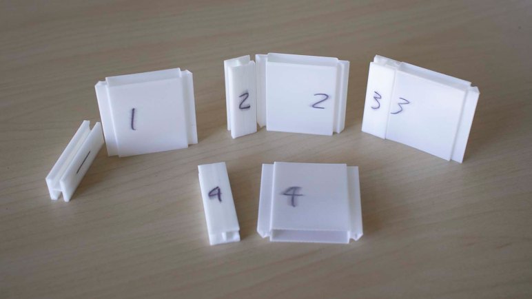
To test these constraints, I printed small samples to see how small tweaks to geometry impacted performance. Each of these small samples consisted of two symmetric pieces. A rigid one representing the rib, printed the way a rib would. Plus a flexible one representing the diffuser, printed in vase mode.
Getting the pieces to fit correctly were a challenge. If the pieces are too loose, a diffuser panel might pop out at inconvenient times. If the pieces are too tight, I would not be able to insert them. The rib section is designed to be symmetric, but the center of the rib depends on 3D printer’s bridging capabilities to work without supports. A bridged surface isn’t as smooth, so there’s some asymmetry between the two slots. There’s also some asymmetry introduced by the interface with the heated print bed also sometimes called “Elephant’s Foot“. And finally, there are imperfections introduced by the 3D printer that cause parts to collide because the two pieces are printed in different orientations. Test sample #1 in the picture above shows print bed orientation of each piece.
These test pieces were useful to explore both CAD dimensions and 3D printer settings before returning to the challenge of building actual pieces for Glow Flow.
