During teardowns, I usually keep any motors I come across, even if I have no idea how I’d use them. Recently I got a pair of hard drive motors spinning again, a good step forward in my quest to better understand brushless direct current (BLDC) motors. I’ve also learned enough to spot some differences between motors. Those that I’ve successfully spun up are three-phase motors, with three sets of coils energized 120 degrees out of phase with each other to turn the rotor. But not all of the motors I’ve disassembled fit this description.
There’s a class of motors with only two sets of coils. Based on what I know of three-phase brushless motors, that would imply two sets of coils are 180 degrees out of phase. A naive implementation would have no control over which direction the rotor would spin, but I’ve found these in cooling fans, where the direction of spin is critical, so there must be more to this story. (If it doesn’t matter which direction the motor spins, we only need a single coil.)
What I’ve observed so far is that a Hall-effect sensor is an important part of this mystery, because I looked up this control chip found inside a computer cooling fan and read it had an integrated Hall sensor.
Searching online for an explanation of how these motors worked, I found this thread “How do single phase BLDC motors start in proper direction?” on Electronics StackExchange. I don’t fully understand the explanation yet, but I do understand these motors aren’t as symmetric as they look. A slight asymmetry allows enforcing the correct turn direction. The hall sensor adds a bit of cost, but I guess it is cheaper than additional coils.
Even better, that thread included a link to Electric Drive Fundamentals on Electropaedia. This page gives an overview of fundamental electromagnetic principles that underpin all electric motors. I knew some of these, but not all of them, and certainly not enough to work through the mathematical formulas. But I hope studying this page will help me better understand the motors I find as I take things apart.
Independent of building an understanding of electromagnetic fundamentals, I also want to better understand Hall sensors critical to running certain motors.
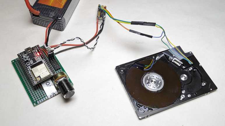
I bought some brushless motor controllers meant for multirotor aircraft: A four-pack intended for quadcoptor drones. But instead of running a motor turning a propeller, I started with a small motor salvaged from a laptop optical drive. (CD or DVD I no longer remember.) It spun up with gusto, and I watched the motor control signals under an oscilloscope. That was interesting, and I shall continue these experiments with more of my teardown detritus: computer hard drive motors.
2.5″ Laptop Hard Drive
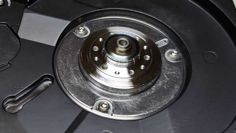
This hard drive was the performance bottleneck in a Windows 8 era tablet/laptop convertible. The computer was barely usable with modern software until this drive was replaced with an SSD. Once taken out of use, I took it apart to see all the intricate mechanical engineering necessary to pack hard drive mechanicals into 5mm of thickness. The detail important today are these three pads on the back, where its original control board made electrical contact with the spindle motor.
They are now an ideal place for soldering some wires.
This motor is roughly the same size as CD/DVD motor. But because I never figured out how to remove the hard drive platter, there is significantly more inertia. This probably contributed to the inconsistent startup behavior I saw. Sometimes the drone motor controller could not spin up the motor, it would just twitch a few times and give up. I have to drop PWM control signal back down to zero throttle and try again. Something (maybe the platter inertia, maybe something else) is outside the target zone of the drive controller’s spin-up sequence. This has been a recurring issue and my motivation to learn more about brushless motors.
Side note: This motor seemed to have a curious affinity for the “correct” orientation. I had thought brushless motors didn’t care much which direction they spun, but when I spun the platter by hand (without power) it would coast for several seconds in the correct orientation but stop almost immediately if I spun it backwards. There’s a chance this is just my wrist, applying more power in one direction versus another, or there might be something else. It might be fun to sit down and get scientific about this later.
3.5″ Desktop Hard Drive
I then switched out the 2.5″ laptop hard drive motor for a 3.5″ desktop computer hard drive motor. This isn’t the WD800 I took apart recently, but another desktop drive I took apart even further back.
I dug it out of my pile because it already had wires soldered to the motor from a previous experiment trying to use the motor as a generator. The data storage platters had been removed from this hard drive so I expected less problems here, but I was wrong. It was actually more finicky on startup and, even if it starts up, never spins up very fast. If I try turning up the speed control signal beyond a certain (relatively slow) point, the coil energizing sequence falls out of sync with the rotor which jerkily comes to a halt.
I was surprised at that observation, because this motor is closest size-wise to the brushless outrunner motors I’ve seen driving propellers. There must be one or more important differences between this 3.5″ hard drive motor and motors used for multirotor aircraft. I’m adding this to a list of observations I hope I can come back to measure and articulate those important differences. Lots to learn still, but at least I know enough now to notice something’s very different with brushless motors built from even fewer wires and coils.
I saw what looked like a WS2812-style RGB LED on the motor controller circuit board and was disappointed when I didn’t see it light up at all. I had expected to see different colors indicating operating status. Instead, the firmware communicates status by pulsing the motor coils to create a buzzing tone. I found an explanation of these beeps on this Drones StackExchange thread titled “When I power up my flight controller and ESC’s, I hear a series of beeps. What do all of the beeps mean?” The answer says the normal sequence is:
Powered-Up: A set of three short tones, each higher pitch than the previous.
Throttle signal detected (arming sequence start): One longer low pitch tone.
Zero throttle detected (arming sequence end): One longer high pitch tone.
(The author of that answer claimed this information came from BLHeli_S manual, but the current edition I read had no such information I could find. Was it removed? If so, why?)
Once the “arming sequence end” tone ends, I could increase my throttle PWM setting to spin up the little motor. It spins up quite enthusiastically! It responded exactly as expected, speeding up and slowing down in response to change in motor control PWM signal.
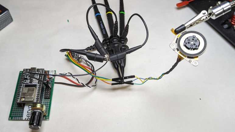
Oscilloscope Time
Once I verified the setup worked, I added my oscilloscope probes to the mix. I wanted to see what the motor power waveforms looked like, and how it compares against what I saw from an old Western Digital hard drive.
That might be a bit jumbled, so here are the phases separately. We can see they are in a sequence, one after another. They all peak at battery power level, and there’s a transition period between peaks. The transitions don’t look as smooth as the Western Digital controller and I don’t have a center wye tap to compare voltage levels against.
Using a brushed DC motors is easy: apply voltage, watch motor shaft turn. I’m exploring brushless DC motors and even the cheapest controller from Amazon had features that I hadn’t even known existed. It is far more sophisticated than a DC motor driver (DRV8833) I explored earlier. To make it actually turn a motor, I’ll start simple with the smallest brushless motor I found in my pile of salvaged hardware.
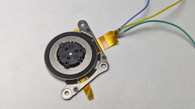
This is a small brushless motor in the spindle of a CD or DVD drive. Based on the fact it is only a few millimeters thick, it was probably salvaged from a laptop optical drive. Lots of wires visible in the pale-yellow ribbon cable. I will need to probe them looking for a set of three or four wires, with a tiny bit of resistance between them, that would indicate coils for the brushless motor.
I probed the set of four contacts closest to the motor, but found no electrical connection between them.
This set of four wires looked promising. They ended abruptly, as if I had cut them off from a larger piece of pale yellow flexible printed circuit. (FPC) I guess the rest of that circuit didn’t look interesting to keep and what they were have been lost to history. I used sandpaper to uncover the copper traces within this cut-off segment. This work was for naught: no electrical connections here either.
This left the large connector of many wires. I noticed the five conductors in the middle are wider than the rest. Each of those led to two contact points on the connector. I started with those and found likely candidates in three of the five wide wires. I’m not sure what the other two were… perhaps power and ground for some other circuit? Whatever they were, I hope they aren’t relevant to my current experiment.
I soldered thin (30 gauge *) wires to each of those points. Using an old AA battery as ~1V source, energizing any two of these wires would result in the motor holding a position. Motor coils confirmed!
A bit of careful cutting and heat-shrink tubing isolated these wires from each other.
For curiosity and learning, I wanted to poke at a commercial brushless motor controller. Thanks to the current popularity of multirotor aircraft, the cheapest option on Amazon that day was a four-pack designed for small quadcoptor drones. Among the listing description is a string “BLHeli_S” that meant nothing to me at the time. Once I received the product and looked it over, I saw “BLHeli_S” written on the label as well, I thought I should at least do a web search to learn more.
BLHeli_S is a development of BLHeli motor control firmware, whose source code is on GitHub. From what I can understand, BLHeli_S is a port to SiLabs 16-bit microcontrollers offering higher performance than original BLHeli 8-bit hardware target. At first, I was thrilled there might be another brushless motor algorithm I could try to learn from, but my enthusiasm quickly cooled when I realized BLHeli_S was written in assembly language for maximum performance. That’s hard core. Understanding that codebase might take more work than I’m willing to put in.
I found additional information on Ardupilot website, which supports BLHeli_S and the even newer BLHeli32 motor controller firmware. In addition to standard RC servo control signal, these controllers also support a more advanced protocol called DShot. It allows higher bandwidth and lower latency, as well as digital checksum to detect and discard corrupted control signals. The most fascinating feature is bidirectional communication, which allows the motor controller to send back information like motor RPM. BLHeli_S also supports OneShot and OneShot125 protocols, but they offer neither the wide compatibility of RC servo style PWM nor the advanced features of DShot. I’m probably never going to touch those.
I could find scattered reviews of BLHeli_S like this one. The most interesting page I stumbled cross was What is DShot ESC Protocol which pointed me to Betaflight. Skimming through Betaflight’s GitHub repository, I found its DShot command driver. It was much easier than trying to find Ardupilot’s implementation. (This is as close as I got. [UPDATE: According to comment by David, the RCOutput_bdshot.cpp file I found handles telemetry coming back from the ESC. Outbound DShot control is handled by RCOutput_serial.cpp in the same directory.])
Looking for implementations outside of those large flight controller projects, I found several GitHub repositories of people taking a stab at it.
I also found an Arduino forum thread of someone asking about bidirectional DShot protocol, and the answer was a link to DShot – the missing Handbook. I doubt I would learn SiLabs assembly to dig into BLHeli firmware itself, but it might be interesting to talk to my new BLHeli_S brushless controllers via bidirectional DShot.
For my first experiment, though, I’m going with the tried-and-true RC servo PWM.
I want to learn how to control brushless motors and how to best tailor their control algorithms to different tasks. Most brushless motors I encounter are very tightly coupled to their associated controller. Occasionally I could examine how a particular pairing worked together, but I don’t know enough to mix and match salvaged motors/controllers to see how different combinations work together. I think I should start with a motor controller that has been designed to accommodate a range of different brushless motors.
The good news: recent popularity of multirotor aircraft (“drones”, “quadcoptors”, etc.) has spawned a product ecosystem of brushless motors and controllers marketed to drone owners. Whether they want to repair, upgrade, or build their own from scratch, many companies compete for their money. I just wanted something cheap as a starting point, so I went with Amazon’s lowest bidder of the day(*) for a four-pack of compact and lightweight brushless motor controllers. Obviously intended to match four motors in a quadcoptor, a pack of four works for me in the interest of redundancy. I may damage a few in my experiments.
Here’s one of the four, just removed from its packaging. I was impressed by its tiny size, the circuit board itself is only about 13mm x 23mm. Thicker red and black wires are for delivering battery power. The thinner wires led to 0.1″ pitch connectors for control signal and signal ground. There are no wires provided for the motor, just three solderable tabs.
I cut away its protective heat-shrink tubing to see inside. On the upper-left I see “S” for white control signal and “-” for signal ground. Probing with my meter indicates signal ground is connected to power ground. This isn’t usually a problem because drones tend to run everything off a single battery but would exclude this controller from circuits isolating logic ground from power ground.
In the center we see two microchips. Larger chip on the right has a logo I don’t recognize, and text SA6288 210. A web search found this SA6288, a gate driver chip designed to drive MOSFET/IGBT transistors to control power for three-phase motors. That fits. It’s probably taking orders from the other chip, then. A microcontroller makes sense given its proximity to the control input signal and four circular pads across the bottom that may be a way to reprogram the chip. I read its markings to be “dB21 F16C C01Q5K 2217”. Search engines clung on to “F16C” and wanted to tell me about the fighter jet, which wasn’t helpful. Maybe I’ve misread one or more characters.
Backside of the chip are all of the power control components, starting with red wire (VBAT) and black wire (GND) for battery power. Relatively large capacitors are visible, and I’m impressed it didn’t need larger electrolytic capacitors. Half of this side are taken up by an array of six modules. From my LX-16A teardown I recognize the logo for Alpha & Omega Semiconductors, but their website didn’t have any information on a 7544 chip. Arrow Electronics says there’s should be an AON7544 N-Channel “AlphaMOS” MOSFET. Two of them per channel would fit with my current understanding of brushless motors.
One of the remaining two chips should be a voltage converter to translate battery power to a lower voltage for the unidentified microcontroller and gate driver chip. But on the lower left, next to the ground wire, is an unexpected entity. It looks like a WS2812 or similar RGB LED module which is much fancier than the single LED I would have expected for an indicator light.
There’s a mysterious name “BLHeli_S” on the Amazon listing and also printed on the front label of this motor controller. A web search found this to be the name of motor control firmware.
(*) Disclosure: As an Amazon Associate I earn from qualifying purchases.
Learning more about brushless DC motor control have been on my to-do list for several years, ever since I learned of another maker’s problems with motor control algorithms that did not suit the task. I’m still not ready to dive into this field yet, but I thought I’ve collected enough potential sources of information that it’s worth writing them down.
ESP32 MCPWM
When I looked at ESP32, one of the features that caught my eye was its motor control pulse-width modulation (MCPWM) peripheral. I used it for my Micro Sawppy rover project which used it to control DC gearmotors in each of the rover’s six wheels. But it is also applicable for controlling two brushless DC motors. Espressif’s ESP32 BLDC control example project looked interesting. Putting it to work directly without modification requires a motor with integrated hall sensor and additional hardware (MOSFETs and gate drivers) I don’t have at the moment. I’ve noticed that MCPWM seems to be missing from more recent Espress microcontrollers, does this mean customer demand hasn’t been high enough to justify continued development? If so, that’s a shame but also a warning I might not want to get too invested in a feature of uncertain future.
SimpleFOC
For something more fully-featured than an Espressif demo, I could look at SimpleFOC. It’s a library for Arduino framework that supports many microcontrollers with Arduino cores. Ranging from the original ATMega328P to STM32 to ESP32. (ESP32 port claims to use its MCPWM peripheral.) This is promising, but SimpleFOC documentation seems to be aimed at people who already knew a lot about brushless motors and know what they want. I need to do more studying before I can absorb information within.
There are a few “reference implementations” for power circuits controlled by SimpleFOC software, but it looks like most of them are out of stock due to the global semiconductor shortage. There are also projects that build on SimpleFOC like this custom wheeled robot controller featured on Hackaday.
VESC
Another open-source project for brushless motor control is VESC. Its documentation is even more opaque to me than SimpleFOC was. (One of them could be built on top of the other for all I know.) What I got out of VESC site is that its primary focus are on brushless motors of sizes suitable for carrying a person around: electric skateboards, scooters, etc.
Theory of Operation
Looking online for beginner-level introductions, I first found How to Make Advanced BLDC Motor Controllers which, despite the name, stayed quite beginner-friendly and did not get very advanced. Here I learned terminology like “trapezoidal drive” which is easier to implement than “sinusoidal drive” which is what field-oriented controllers like SimpleFOC and VESC does. I also learned of dangers like “shot-through condition” which risks short-circuiting and blowing out our controller circuit and/or our power supply.
Of course, this study syllabus is only important because I want to understand what’s going on behind the scenes. If I just want to spin a motor, the easiest thing to do is to buy a commercial controller. Which I’ve also done to see what I can learn.
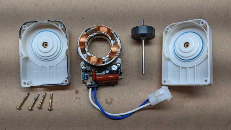
I looked over the control circuit board for a Western Digital WD800 hard drive and failed to find any documentation relating to chips I found onboard. Oh well. Maybe I’ll have better luck with another drive. For this drive, I continue on to familiar territory: take it apart to marvel at all those mechanical wonders within. As a side effect, this will also make all data stored on this drive functionally inaccessible.
The only tricky part with disassembly is that two of the Torx screws holding lid in place were hidden under the label sticker.
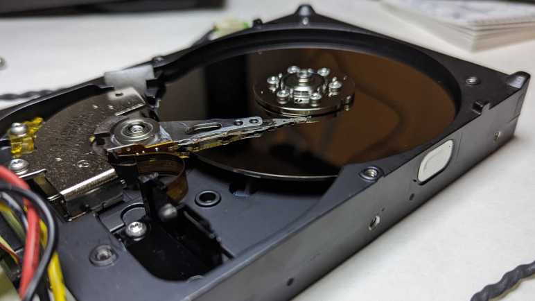
Inside we see a single platter. I’m pretty sure 2002 was recent enough for multi-platter drives, which would mean 80GB was not the highest capacity model in this product line even when it was new.
A translucent yellow bracket limits possible range of motion with read-write head. A small magnet is embedded on one end, but I don’t know its design intent. Perhaps it held the head in place when there’s no power? This bracket is held by a single screw and had to be removed before the read-write head can pivot far enough to clear the platter.
Visible in this picture under the read-write head voice coil is one of two very powerful magnets buried inside this hard drive, the other one is mirror-image on top and already removed in this picture. I have yet to figure out how to nicely separate the magnets from the thick steel cage they are glued(?) to.
Once cleared I could remove the read-write head and platter. There was a pleasant surprise when the platters were removed: I saw three more screws holding the motor in place. Previous HDD teardowns found motors press-fit into the aluminum and impractical to remove. This was the first brushless hard drive motor spindle I could easily remove and store away for potential future projects. Learning more about brushless DC motors is on my to-do list, and I will need motors to experiment with.
This is just the latest in a series of desktop-sized 3.5″ HDD I’ve taken apart. What I haven’t done much of is taking apart their laptop-sized counterpart 2.5″ HDD.
I took apart a Fantom Drives FDU80 and found within a Western Digital WD800 3.5″ hard disk drive with 80GB capacity. I’m sure that was a lot of space in its day, but it’s quite small by current standards. Combined with the fact that it used now-outdated PATA interface, there’s no point trying to put this drive back into service storing data. However, it is still a marvel of engineering and manufacturing and I want to poke around to learn what I can.
One thing that caught my attention was the motor power interface, showing four contact points. My past hard drive adventures always found three contact points on the brushless motor, why is this different? My experience with four-conductor motors are stepper motors used in 3D printers. Is this an electrical cousin?
Removing four Torx screws allowed circuit board removal, which was easy because electrical connection between the board and mechanical drive bits are done with springy metal fingers. Now I can probe electrical resistance between these four points, named via their label on the circuit board E50 through E53.
Resistance (Ohms)
E50
E51
E52
E53
E50
0
1.1
1.1
1.1
E51
1.1
0
1.9
1.9
E52
1.1
1.9
0
1.9
E53
1.1
1.9
1.9
0
Measuring small resistance values is a little tricky, we’re getting into margins of errors. But it is clear this is not an electrical cousin of a stepper motor. A 4-wire stepper would have two pairs of wires that are electrically independent from each other, but these wires all have connections to each other. It appears E50 has the same resistance to the remaining three, and the resistance between any of those three are roughly double the resistance to E50. This is consistent with a brushless DC motor with “Wye” winding style with E50 as the center.
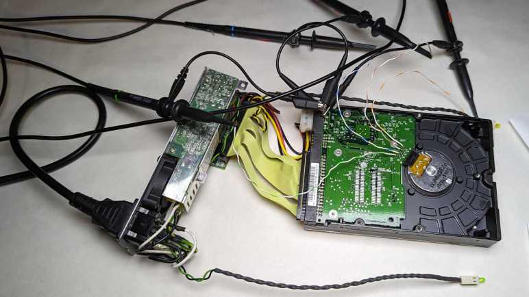
I wanted to see what the motor control signals look like under an oscilloscope, so I soldered wires to each motor point and connected them to my Siglent four-channel oscilloscope. I also soldered a wire to the ground wire of power input and connected all four probes’ ground reference alligator clip to that ground wire.
E50 center of the Wye is connected to yellow channel 1
E51 to magenta channel 2
E52 to cyan channel 3
E53 to green channel 4
With everything hooked up, I powered up the hard drive and the oscilloscope. Siglent has an “Auto Setup” button that can quickly configure the scope for simple tasks. If this were easy, I expect to see three sinusoidal waves 120 degrees out of phase.
The jumble told me Auto Setup couldn’t handle this task. There’s enough pattern for me to see It’s not random noise but I don’t know how to interpret what I see. Trying to make sense of this plot, I started by giving all four channels identical vertical scale. A repeating pattern emerged, and I zoomed in a little bit.
From here I can see E50 (channel 1 yellow) spends most of its time either at 0V or 6V, and when it is at 0V all the other channels are usually at 0V as well. Beyond that, this trace is still quite noisy with other channels anywhere from 0V to 12V. There’s a lot happening and, trying to decipher things one at a time, I pressed “Run/Stop” to see individual snapshots. I mostly get a trace I don’t understand, but occasionally I see a simple picture consistent with a state I do:
The motor control board energizes coils in a sequence to keep the rotor spinning. Sometimes this means peak voltage difference across two of the coils while the third is close to same voltage as center of the wye winding. (Yellow channel 1.) This could happen in one of two directions. Three coils * two directions = six possibilities, after pressing “Run/Stop” enough times I could catch examples of all six.
Most of the time, though, it doesn’t look that obvious. as we’re in some intermediate state transitioning between those six endpoints. I couldn’t see any pattern at this timescale, I had to zoom out from 5us to 500us.
Looking at which coil spends time at 12V, I can see them cycling through a repeating pattern magenta-cyan-green (or channel 2/3/4). This is a cycle, but not a sinusoidal one like I had expected. The key here is noticing what matters here is not voltage relative to power supply ground, but the voltage relative to yellow center 1: the center of the wye. It spends a lot of time near 6V but doesn’t stay at exactly 6V. Looking at how yellow voltage level varies we can see how that would approximate a sine wave relative to each of the coils. It may not be a perfect sine wave, but I guess it’s close enough to drive this brushless motor. I had expected the wye center to be connected to ground and each of the coils given positive or negative sinusoidal voltage. But this controller connects the coils to either ground or 12V and vary voltage of Wye center. I’m sure the engineering team decided on this approach for good reasons, but I don’t understand motors well enough (yet) to see them.
Some time ago I had a broken hobby servo that I traced to a burned-out control board. Since the motor itself and its geartrain are still good, I thought I could use it as a gearmotor but I didn’t have an immediate project. What I did have immediately on hand was a few LEDs on the workbench, so I reversed the power flow: I connected the LED to the motor and spun the servo shaft. The former output shaft is now where I input my mechanical energy, and the former motor power input pins have become electrical output pins of a very simple and crude power generator. Making the LED glow a dull red was fun for a few minutes before some gears failed. Clearly, there is room for improvement.
I think of that experience every time I take apart a failed hard disk drive, which I do for a few reasons: first, because I wanted the powerful magnets within a hard drive. Second, because disassembling the data platters make my data very difficult to steal. And third, because all that precision machining is very pretty to look at! The typical finish line for this activity is a hard drive chassis with a brushless motor that formerly spun the platters.
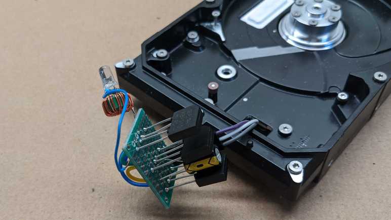
I’ve wanted to try turning such a motor into a generator as well, a more complex project that I had put off until now. I started by soldering wires to the motor’s three input pins.
From here I could connect any two of these three wires to my cheap oscilloscope. When I spin the motor by hand, I can see a small sinusoidal AC signal. There should be three sets of these waveforms, one between each pair of wire. (1-2, 2-3, and 1-3.) In order to convert this to DC power suitable for lighting up a LED, I will need rectifiers to turn that AC power into DC. I have a motley collection of rectifiers salvaged from various electronics teardowns, but I don’t know if it is important that I use three matching units. Since they are cheap, I decided to buy a pack of twenty rectifiers(*) just so I have three identical units for this experiment.
Rectifiers in hand, I picked two out of the three wires from my motor and wire them up to the two pins labeled “AC”. Repeat for two more rectifiers each for one of the other two wire pairings, then connect all three “+” and “-” together in parallel with a capacitor. I then put my DC voltmeter across them and started playing with the motor spindle. Unsurprisingly, there’s some kind of startup barrier. If I just casually spin the motor about the same speed I turn the volume knob on audio equipment, nothing happens. But if I give it a fast twist like I’m spinning a top, I can see the capacitor voltage jump to about 1V.
A single volt is not enough to directly illuminate a LED, but I have built lots of little “Joule thief” boost converters that can light LEDs from tired alkaline batteries. They only need about 0.4V to do their thing, but I don’t know if there’s enough current. I soldered one of them to this circuit and gave the motor a good twist. I was rewarded by a brief blink of LED. I count that as success!
The next step in this exploration is to build something so that motor can spin faster and more consistently than what I can accomplish with a flick of the wrist. What form of mechanical energy should I try to harness for power generation?
(*) Disclosure: As an Amazon Associate I earn from qualifying purchases.
Today I learned brushless DC (BLDC) motor controllers might tailor their motor start up procedure for their designed use case. This is notable because depending on the specialization, it might make them unsuitable for repurposing to other projects. This is not something I had experienced as my own projects have used either stepper motors, brushed DC motors, or self-contained modules like RC hobby servo motors. But another local maker tried to repurpose some brushless motors for a project, and made a discovery worthy of writing down for future reference.
The motors were sold as electric skateboard motors, similar but not identical to this Amazon item. (*) The rubber wheel was removed, and the motor mounted inside a 3D printed gearbox in a similar manner to the brushed DC motors inside SGVHAK rover wheels. The resulting assembly worked well enough on a workbench when driven by the controller module that came with the motor. But when placed under load, the motor was unable able to start from standstill. It was stuck in an endless loop of try, fail, wait, repeat. We had to give the mechanism a push and start it moving before the skateboard motor controller could take over.
Unsatisfied with this behavior, the project moved on to a dedicated brushless motor control chip purchased from Digi-Key and a circuit board was designed around it. This custom BLDC controller module replaced the default unit. When starting under load, it would twitch for a few seconds, then give up and stop. It was only able to run the motor in open air or after a push. So while the actual behavior was different, for practical purposes the two controllers were equally useless for the project.
If it was just one controller, we can blame a faulty unit. But two completely different controllers exhibiting similar behavior in different ways tell us something else is going on. After some investigation, the conclusion is that both controllers are behaving by design. Neither controller were capable of starting a loaded brushless motor from standstill because neither were intended to.
The first controller was tailored for electric skateboards. It does not need to be able to start moving a heavy load from standstill, because skateboard riders usually start off with a kick as they engage their electric throttle. In fact, its inability to move until the skateboard is already moving can be argued as a safety measure to ensure a board can’t take off unexpectedly.
The second controller, after some digging, was discovered to be designed for fans. Unsurprising, then, that it was able to start the motor spinning in air. And again the inability to start under load might even be a safety measure: an air moving fan encountering resistance on startup indicates an obstruction that must be removed.
While instructive, learning this lesson has put the project no closer to a solution. Motor start up behavior isn’t something typically stated up front when shopping for BLDC controllers, as seen in this Amazon “brushless motor controller” query result. (*) More research is required.
But at least we now know it is a factor.
(*) Disclosure: As an Amazon Associate I earn from qualifying purchases.