I’ve dusted off my Dell Inspiron 7577 laptop and set it up as a light-duty virtualization server running Proxmox Virtual Environment. My InfluxDB project and my Plex server both run on top of Ubuntu Server, and Proxmox has a very streamlined process to set up virtual machines from installation media ISO file. I got those two up and running easily.
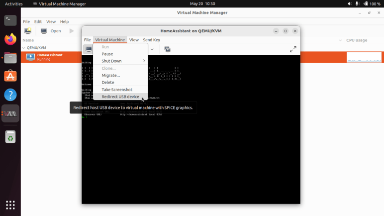
Setting up Home Assistant OS under Proxmox took more work. Unlike Virtual Machine Manager, Proxmox doesn’t have a great way to import an existing KVM virtual machine image, which is how Home Assistant OS was distributed. I tried three sets of instructions without success:
- Proxmox documentation describes how to import an OVF file. HAOS is available as an OVA file, which is a tar archive of an OVF plus its associated files. I unpacked that file to confirm it did include an OVF file and tried using that, but the disk image reference was considered invalid by the import tool and ignored.
- GetLabsDone: I got far enough to get a virtual machine, but it never booted. I got some sort of infinite loop, consuming 100% of one CPU while showing a blank screen.
- OSTechNix: Slightly different procedure but the same results: blank screen and 100% of one CPU.
Then I found a forum thread on Home Assistant forums, where I learned GitHub user @tteck has put together a script to automate the entire process. I downloaded the script to see what it is doing. I understood it enough to see it closely resembled the instructions on GetLabsDone and OSTechNix, but not enough to understand all the differences. I felt I at least understood it enough to be satisfied it’s not doing anything malicious, so I ran the script on my Proxmox VE instance and it worked well to get Home Assistant OS up and running. Looking at the resulting machine properties in Proxmox UI, I see a few differences. The system BIOS is “OVMF” instead of default “SeaBIOS” and there’s an additional 4MB “EFI disk”. I could try to recreate a Home Assistant VM using these parameters, but since HAOS is already up and running so I’m not particularly motivated to perform that experiment.
A side note on auditing @tteck‘s script haos-vm.sh: commands are on a single line no matter their length, so I wanted a way to line-wrap text files at the command-line and learned about the fold command. Instead of dumping out the script with “more haos-vm.sh” I can line wrap it at spaces with “fold -s haos-vm.sh | more“.
After Home Assistant OS fired up and I could access its interface in a web browser, the very first screen has an option for me to upload a backup file from my previous HAOS installation. I uploaded the file and a few minutes later the new HAOS virtual machine running under Proxmox VE took over all functions with only a few notes:
- The “upload…” screen spinner kept spinning even after the system was up and running. I saw the CPU and memory usage dropped in Proxmox UI and thought things were done. I opened up a new browser tab to
http:/homeassistant.local:8123/and saw Home Assistant was indeed up and running, but the “Uploading…” spinner never stopped. I shrugged, closed that first spinner tab, and moved on. - The nightly backup automation carried over, but I had to manually re-add the network drive used for backups and point the automation back at the just-re-added storage location target.
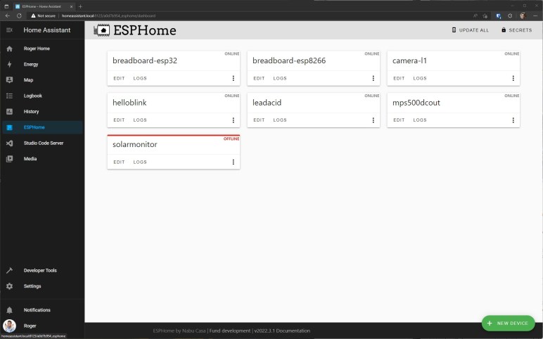
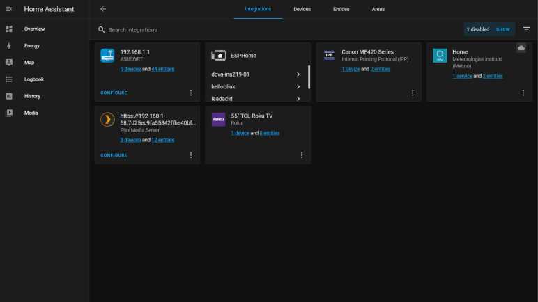
- All my ESPHome YAML files carried over intact, but I had to manually re-add ESPHome integration. Then all the YAML files were visible and associated with their respective still-running devices around the house, who seamlessly started reporting data to the new HAOS virtual machine.
I have done several Home Assistant migrations by now, and it’s been nearly seamless every time with only minor adjustments needed. I really appreciate how well Home Assistant handles this infrequently-used but important capability to backup and restore.
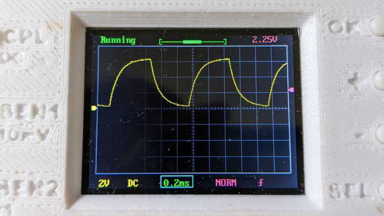
After I got Home Assistant up and running under Proxmox VE on the new machine, I wondered how long it’ll be before I run into my first technical problem with this setup. The answer: about 36 hours.