Performing AS7341 Sensor Integration in Parallel Resolved Mozzi Glitches

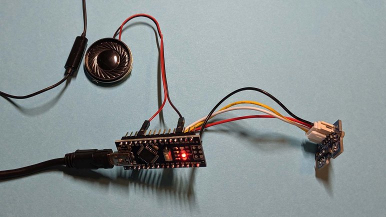
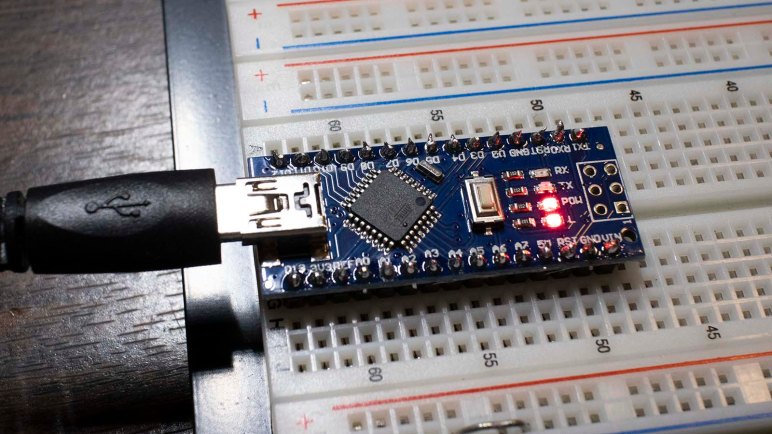
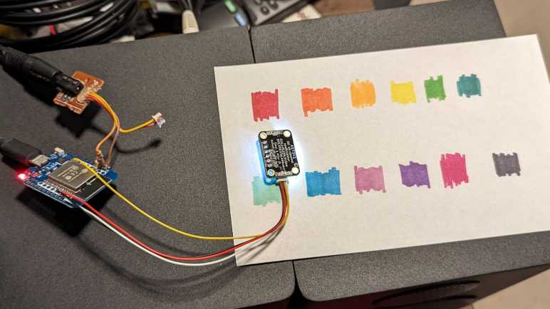
I’ve set up an ESP32 development board for interfacing with both an AS7341 spectral color sensor as well as Mozzi audio generation libraries. This is a follow-up to my project doing the same with an AVR ATmega328-based Arduino Nano. On those AVR boards, trying to compile Mozzi with Adafruit’s AS7341 library would fail due to conflict between Mozzi’s twi_nonblock I2C library and Arduino’s Wire I2C library.

[...]\libraries\Mozzi-master\twi_nonblock.cpp.o (symbol from plugin): In function `initialize_twi_nonblock()':
(.text+0x0): multiple definition of `__vector_24'
[...]\libraries\Wire\utility\twi.c.o (symbol from plugin):(.text+0x0): first defined here
collect2.exe: error: ld returned 1 exit status

exit status 1

Compilation error: exit status 1

My earlier project solved that problem by avoiding Arduino Wire library, writing AS7341 interface code with twi_nonblock while using Adafruit’s library as a guide. (But unable to copy code straight from it.) However, twi_nonblock is excluded from non-AVR platforms like ESP32. The good news is that we avoid above compiler error, the bad news is that we’re on our own to find a non-blocking I2C API. For an ESP32, that meant dropping down to Espressif’s ESP-IDF I2C API. I believe that’s within my coding capabilities, but there was an easier way.

Why does as7341.readAllChannels() consume so much time that it causes Mozzi audio glitches? Arduino Wire’s blocking I2C operations are certainly a part of that process, but most of that time is spent in AS7341 sensor integration. as7341.readAllChannels() starts an integration and waits for it to complete before returning results, blocking our Arduino sketch the entire time. But Adafruit foresaw this problem and included a provision in their AS7341 library: we can start an integration without blocking on it. Our sketch resumes code execution, allowing Mozzi to update audio while integration occurs in parallel. Once integration is complete, we can retrieve the values and do all the same things we would do for results of as7341.readAllChannels().

This concept was illustrated in the Adafruit example sketch reading_while_looping, which I thought was promising when I reviewed all example sketches earlier. I couldn’t try it on an AVR due to Wire/twi_nonblock compiler conflict, but I could give it a shot on this ESP32. I started with the reading_while_looping example sketch and converted it over to a Mozzi sketch. First by moving existing code in loop() into updateControl(), leaving just a call to audioHook() inside loop(). For my first test I didn’t need anything fancy, so I just had Mozzi play a steady 440Hz sine wave in updateAudio(). (A440 is the note used by western classical music orchestra to verify all instruments are in tune with each other.)

The first run was a disaster! Audio glitches all over the place, but I knew there was room for improvement. There was an entirely unnecessary delay(500), which I deleted. Interleaved with the parallel integration is a blocking integration to our old friend as7341.readAllChannels(). I don’t understand why the blocking code is in the middle of a non-blocking example, but I deleted that, too. This removed most of the problems and left a little recurring audible click. Looking over what’s left, I noticed this sketch made quite a number of calls to Serial.println(). After their removal I no longer heard glitches in Mozzi audio.

I2C communication is still performed with Arduino Wire library. But this experiment empirically showed the communication is fast enough on an ESP32 that Mozzi does not audibly glitch despite Wire’s blocking nature. This is much easier than dropping down to ESP-IDF I2C API. Also, this approach portable to other non-AVR Mozzi platforms like Teensy.

After this successful experiment, I modified one of Emily’s color organ sketches and the resulting pull request shows the changes I had to make. They were quite minimal compared to rewriting everything with twi_nonblock.

Playing with Mozzi was a fun challenge catering to its timing requirements. But as I proceed to play with AS7341, I’d prefer to shed Mozzi timing constraint and focus on other capabilities of this sensor.


Code for this exploration is publicly available on GitHub

JST-SH (STEMMA QT) and 3.5mm (Headphone Audio) Jack for ESP32 Mini

It was an interesting challenge to write code which talked to an AS7341 spectral color sensor using Mozzi’s twi_nonblock API for I2C communication. I referenced Adafruit’s AS7341 library heavily, but I couldn’t copy much (any?) code directly on account of the differences between Arduino Wire I2C and twi_nonblock. But twi_nonblock is only supported for AVR chips, and Mozzi runs on additional architectures such as ESP32. Can I get AS7341 to play nice with Mozzi on those platforms?

For my earlier AVR adventures, I laid out my hardware components on a breadboard. This time, with a bit more confidence, I’m going to wire the components point-to-point without a breadboard. Which means I am free to use my breadboard unfriendly ESP32 Mini board and equip it for integrating Mozzi with AS7341.

For Mozzi audio output on AVR ATmega328 Arduino Nano, I wired an earbud headphone directly to pin D9. I was comfortable doing this as the ATmega328 is a fairly robust chip tolerant of simple direct designs like this. However, the ESP32 is not designed for similar scenarios, and I should take a bit of effort to make sure I don’t kill my chip. Thankfully Mozzi has a guide on how to connect audio with an RC (resistor+capacitor) filter which should be better than nothing to protect the ESP32 pin used for audio output. According to Mozzi documentation, both GPIO25 and GPIO26 are used. I soldered my resistor to GPIO26.

For audio hardware interface, I used a 3.5mm jack salvaged from a cheap digital photo frame I tore down long ago. (Before I started documenting my teardowns on this blog.) This was technically the video output port with four conductors inside the 3.5mm TRRS jack for composite video, audio left, audio right, and ground. But I only need two of the wires: ground plus one audio signal. The other two wires were left unused here.

For AS7341 interface, I dug up my pack of JST-SH connectors (*) originally bought for a BeagleBone Blue but went unused. This is mechanically compatible with Adafruit’s STEMMA QT connectors on their AS7341 breakout board #4698. However, the wire colors in my pack of pre-crimped connectors do not match convention for how they are used in a STEMMA QT. Testing for continuity, I found the following:

  • White = Ground (GND) should be black
  • Yellow = Power (VIN) should be red
  • Black = Data (SDA)
  • Red = Clock (SCL)

I briefly contemplated popping individual pre-crimped wires out of the connector and rearranging them, then I decided this was a quick hack prototype and I didn’t care enough to spend time fiddling with tiny fussy connectors. (This is why I bought them pre-crimped!) Hopefully this decision wouldn’t come back to bite me later. I soldered I2C data wire (black) to GPIO21 and I2C clock wire (red) to GPIO22. Power and ground went to their respective pins on the ESP32 Mini.

This should be enough hardware for me to start investigating the software side.


(*) Disclosure: As an Amazon Associate I earn from qualifying purchases.

AS7341 Spectral Color Sensor with Mozzi on AVR Arduino

Looks like I will never learn how to build custom configurations for AS7341 SMUX, but at least I have presets I could copy/paste and that’s good enough for my hobbyist level project. The goal is to convert I2C communication from Arduino’s standard Wire library to the twi_nonblock library bundled as part of Mozzi library. Arduino Wire library would block execution while I2C communication is ongoing, which causes audible glitches with Mozzi sketches. Converting to twi_nonblock avoids that issue.

Using Adafruit’s AS7341 Arduino library and sample sketches as my guide, it was relatively straightforward to converting initialization routines. Partly because most of them were single-register writes, but mostly because non-blocking isn’t a big concern for setup. I could get away with some blocking operations which also verified I2C hardware was working before adding the variable of nonblocking behavior into the mix.

To replicate Adafruit’s readAllChannels() behavior in a nonblocking manner, I split the task into three levels of state machines to track asynchronous actions:

  • Lowest level state machine tracks a single I2C read operation. Write the address, start a read, and copy the results.
  • Mid level state machine pulls data from all 6 AS7341 ADC. This means setting up SMUX to one of two presets then waiting for that to complete. Start sensor integration, then wait for that to complete. And finally copy sensor results. Each read operation is delegated to the lower level state machine.
  • High level state machine runs the mid-level state machine twice, once for each SMUX preset configuration.

Once that high level state machine runs through both SMUX preset configurations, we have data from 10 spectral sensors. The flicker detector is the 11th sensor and not used here. This replicates the results of Adafruit’s readAllChannels() without its blocking behavior. Getting there required an implementation which is significantly different. (I don’t think I copied any Adafruit code.)

While putting this project together, my test just printed all ten sensor values out to serial console. In order to make things a little more interesting, I brought this back full circle and emulated the behavior of Emily Velasco’s color organ experiment. Or at least, an earlier version of it that played a single note depending on which sensor had returned highest count. (Emily has since experimented with vibrato and chords.) I added a lot of comments my version of the experiment hopefully making it suitable as a learning example. As a “Thank You” to Emily for introducing me to the AS7341, I packaged this project into a pull request on her color organ repository, which she accepted and merged.

This is not the end of the story. twi_nonblock supports only AVR-based Arduino boards like the ATmega328P-based Arduino Nano I used for this project. What about processors at the heart of other Arduino-compatible boards like the ESP32? They can’t use twi_nonblock and would have to do something else for glitch-free Mozzi audio. That’ll be a separate challenge to tackle.


Code for this project is publicly available on GitHub.

Unrolling Adafruit AS7341 readAllChannels()

After successfully reading an AS7341’s product ID via a non-blocking I2C API, I have gained confidence I can replicate any existing AS7341 library’s actions with the non-blocking I2C API. This way it will play nice with Mozzi library. I decided to focus on Adafruit_AS7341::readAllChanels() because it seemed like the most useful one to convert to non-blocking operation. It was used in multiple examples as well as Emily’s color organ project.

bool Adafruit_AS7341::readAllChannels(uint16_t *readings_buffer) {

  setSMUXLowChannels(true);        // Configure SMUX to read low channels
  enableSpectralMeasurement(true); // Start integration
  delayForData(0);                 // I'll wait for you for all time

  Adafruit_BusIO_Register channel_data_reg =
      Adafruit_BusIO_Register(i2c_dev, AS7341_CH0_DATA_L, 2);

  bool low_success = channel_data_reg.read((uint8_t *)readings_buffer, 12);

  setSMUXLowChannels(false);       // Configure SMUX to read high channels
  enableSpectralMeasurement(true); // Start integration
  delayForData(0);                 // I'll wait for you for all time

  return low_success &&
         channel_data_reg.read((uint8_t *)&readings_buffer[6], 12);
}

Examining this code, we can see it does the same thing twice, differing only in a single boolean parameter to setSMUXLowChannels. This reflects AS7341 architecture where we have more sensors than ADCs so we have to configure SMUX to read a subset then reconfigure SMUX to read remaining sensors.

void Adafruit_AS7341::setSMUXLowChannels(bool f1_f4) {
  enableSpectralMeasurement(false);
  setSMUXCommand(AS7341_SMUX_CMD_WRITE);
  if (f1_f4) {
    setup_F1F4_Clear_NIR();
  } else {
    setup_F5F8_Clear_NIR();
  }
  enableSMUX();
}

Digging into setSMUXLowChannels we see the following actions:

  1. enableSpectralMeasurement disables a register bit to turn off spectral measurement, necessary preparation for SMUX reconfiguration.
  2. setSMUXCommand flips a different register bit to notify AS7341 that a new SMUX configuration is about to be uploaded.
  3. Upload one of two SMUX configurations, depending on boolean parameter.
  4. enableSMUX repeatedly reads a register bit until it flips to 0, which is how AS7341 signifies that SMUX reconfiguration is complete.

Steps 1-3 above are I2C writes and can be done quickly. Step 4 will add complication: not only is it an I2C read, but we might also need to read it several times before the bit flips to zero.

Backing out to readAllChannels, we see spectral measurement bit is flipped back on after SMUX reconfiguration. According to the datasheet, flipping this bit back on is a signal to start a new reading. How do we know when sensor integration is complete? That’s indicated by yet another register bit. delayForData repeatedly reads that until it flips to 1, clearing the way for us to read 12 bytes of sensor data. Representing data from all six ADCs channels, each of which gives us 16 bits (2 bytes) of data.

Unrolling all of the above code in terms of I2C operations, readAllChannels breaks down to:

  1. I2C register write to turn OFF spectral measurement.
  2. I2C register write to notify incoming SMUX configuration data.
  3. I2C write to upload SMUX configuration for ADC to read sensors F1 through F4, plus Clear and NIR channels.
  4. Repeated I2C read for “SMUX reconfiguration” flag until that bit flips to 0.
  5. I2C register write to turn ON spectral measurement. (Starts new sensor integration.)
  6. Repeated I2C read for “Sensor integration complete” flag until that bit flips to 1.
  7. I2C read to download sensor data
  8. Repeat 1-7, except step #3 uploads SMUX configuration for sensors F5 through F8 instead of F1 through F4.

I like this plan but before I roll up my sleeves, I wanted to take a closer look at SMUX configuration.


Code for this project is publicly available on GitHub.

Hello AS7341 ID via Non-Blocking I2C

I’ve refreshed my memory of Mozzi and its twi_nonblock API for non-blocking I2C operations, the next step is to write a relatively simple Hello World to verify I can communicate with an AS7341 with that API. While reading AS7341 datasheet I noted a great candidate for this operation: product ID and revision ID registers.

In order to use twi_nonblock we need to break a blocking read() up to at least three non-blocking steps in order to avoid glitching Mozzi sound:

  1. We start with an I2C write to tell the chip which register we want to start from. Once we set parameters, I2C hardware peripheral can do the rest. In the meantime, we return control to the rest of the sketch so Mozzi can do things like updateAudio(). During each execution of updateControl() we check I2C hardware status to see if the write had completed. If it’s still running, we resume doing other work in our sketch and will check again later.
  2. If step 1 is complete and address had been sent, we configure I2C hardware peripheral to receive data from A7341. Once that has been kicked off, we return control to the rest of the sketch for updateAudio() and such. During each execution of updateControl() we check I2C hardware status to see if data transfer had completed. If it’s not done yet, we resume running other code and will check again later.
  3. If data transfer from AS7341 is complete, we copy the transferred data into our sketch and our application logic can take it from there.

My MMA_7660 sketch tracked above states #1-3 within updateControl(), following precedence set by Mozzi’s ADXL354 example. But that was a simple sensor to use, we just had to read three registers in a single operation. AS7341 is a lot more complex with multiple different read operations, so I pulled that state machine out of updateControl() and into its own method async_read(). The caller can keep calling async_read() on every updateControl() until the state reaches ASYNC_COMPLETE, at which point the process stops waiting for data to be copied and processed. Whenever the caller is ready to make another asynchronous read, they can set the state to ASYNC_IDLE and the next async_read() will start the process again.

As a test of this revamped system, I used it to read two bytes from AS7341 starting at register 0x91. 0x91 is for revision ID and the following byte 0x92 is the product ID. I wasn’t sure what to expect for revision ID, I got zero. But according to the datasheet product ID is supposed to be 0x09, and that matches what I retrieved. A great start! Now I can dig deeper and figure out how to read its sensors with nonblocking I2C.


Code for this project is publicly available on GitHub.

Refresher on Mozzi Timing Before Tackling AS7341

I’ve decided to tackle the challenge of writing a Mozzi-friendly way to use an AS7341 sensor, using nonblocking I2C library twi_nonblock. At a high level, this is a follow-up to my MMA7660 accelerometer Mozzi project several years ago. Due to lack of practice in the meantime I have forgotten much about Mozzi and need a quick refresher. Fortunately, Anatomy of a Mozzi sketch brought most of those memories back.

I connected a salvaged audio jack to the breadboard where I already had an Arduino Nano and my Adafruit AS7341 breakout board. (The AS7341 will sit idle while I refamiliarize myself with Mozzi before I try to integrate them.) After I confirmed the simple sine wave sketch generated an audible tone on my test earbuds, I started my first experiment.

I wanted to verify that I understood my timing constraints. I added three counters: the first is incremented whenever loop() is called. The second when Mozzi calls the updateControl() callback, and the third for updateAudio() callback. Inside loop(), I check millis() to see if at least one second has passed. If it had, I print values of all three counters before resetting them back to zero. This test dumps out the number of times each of these callbacks occur every second.

loop 165027 updateControl 64 updateAudio 16401
loop 164860 updateControl 63 updateAudio 16384
loop 165027 updateControl 64 updateAudio 16401
loop 164859 updateControl 64 updateAudio 16384
loop 165027 updateControl 64 updateAudio 16401
loop 164860 updateControl 63 updateAudio 16384
loop 165028 updateControl 64 updateAudio 16400
loop 164859 updateControl 64 updateAudio 16385
loop 165027 updateControl 64 updateAudio 16400
loop 164858 updateControl 64 updateAudio 16384
loop 165029 updateControl 63 updateAudio 16401
loop 164858 updateControl 64 updateAudio 16384
loop 165027 updateControl 64 updateAudio 16401
loop 164858 updateControl 64 updateAudio 16384
loop 165029 updateControl 64 updateAudio 16400
loop 164860 updateControl 63 updateAudio 16384

Arduino framework calls back into loop() as fast as it possibly can. In the case of this Mozzi Hello World, it is called roughly 165,000 times a second. This represents a maximum on loop() frequency: as a sketch grows in complexity, this number can only drop lower.

In a Mozzi sketch, loop() calls into Mozzi’s audioHook(), which will call the remaining two methods. From this experiment I see updateControl() is called 63 or 64 times a second, which lines up with the default value of Mozzi’s CONTROL_RATE parameter. If a sketch needs to react more quickly to input, a Mozzi sketch can #define CONTROL_RATE to a higher number. Mozzi documentation says it is optimal to use powers of two, so if the default 64 is too slow we can up it to 128, 256, 512, etc.

We can’t dial it up too high, though, before we risk interfering with updateAudio(). We need to ensure updateAudio() is called whenever the state of audio output needs to be recalculated. Mozzi’s default STANDARD mode runs at 16384Hz, which lines up with the number seen in this counter output. If we spend too much time in updateControl(), or call it too often with a high CONTROL_RATE, we’d miss regular update of updateAudio() and those misses will cause audible glitches. While 16 times every millisecond is a very high rate of speed by human brain standards, a microcontroller can still do quite a lot of work in between calls as long as we plan our code correctly.

Part of a proper plan is to make sure we don’t block execution waiting on something that takes too long. Unfortunately, Arduino’s Wire library for I2C blocks code execution waiting for read operations to complete. This wait is typically on the order of single-digit number of milliseconds, which is fast enough for most purposes. But even a single millisecond of delay in updateControl() means missing more than 16 calls to updateAudio(). This is why we need to break up operations into a series of nonblocking calls: we need to get back to updateAudio() between those steps during execution. Fortunately, during setup we can get away with blocking calls.

New Project: Mozzi + AS7341

After looking at Adafruit’s AS7341 library and its collection of example sketches, I will now embark on a new project: make Mozzi play nice with AMS AS7341 sensor. If successful, it would solve a problem for my friend Emily Velasco who got me interested in the AS7341 to begin with. Her project uses Mozzi library to generate sounds but calls into AS7341 API would cause audible pops.

The problem is that AS7341 libraries from Adafruit and DFRobot both use Arduino’s Wire library for I2C communication. (Adafruit actually goes to their BusIO library which then calls into Wire.) These are blocking calls meaning the microcontroller can’t do anything else until the operation completes. This is especially problematic for I2C reads: We have to perform a write to send the register address we want to read from, then start a read operation, and wait for the data to come in. This operation is usually faster than an eyeblink, but that’s still long enough to cause a pop in Mozzi audio.

To help solve this problem, Mozzi includes a library called twi_nonblock. It allows us to perform I2C operations in a non-blocking manner so Mozzi audio can continue without interruption. Unfortunately, it is a lot more complicated to write code in this way, and it only supports AVR-based Arduino boards, so people usually don’t bother with it. Mozzi includes an example sketch, altering sounds based on orientation of an ADXL345 accelerometer. A few years ago, I took that example and converted it to run with a MMA7660 accelerometer instead.

If I could interface with an AS7341 using Mozzi’s twi_nonblock, it would allow color-reactive Mozzi sketches like Emily’s to run on AVR-based Arduino boards without audio glitches. But the AS7341 is far more complex than a MMA7660 accelerometer. I’ve got my work cut out for me but if it works, I will gain a great deal of confidence and experience on the AS7341 as well as a refresher on working with Mozzi.


Code for this project is publicly available on GitHub.

Arduino Mozzi Wilhelm Exercise

After completing a quick Mozzi exercise, I found a few problems that I wanted to fix in round 2.

The first problem was the use of audio clip from Portal 2. While Valve Software is unlikely to pursue legal action against a hobbyist exercise project for using one short sound from their game, they indisputably own the rights to that sound. If I wanted a short code exercise as any kind of example I can point people to, I should avoid using copyrighted work. Hunting around for a sound that would be recognizably popular but less unencumbered by copyright restrictions, I settled on the famous stock sound effect known as the Wilhelm scream. Information about this effect — as well as the sound clip itself — is found all over, making it a much better candidate.

The second problem was audible noise even when not playing sampled audio. Reading through Mozzi sound code and under-the-hood diagram I don’t understand why this noise is coming through. I explicitly wrote code to emit zero when there’s no sound, which I thought meant silence, but something else was happening that I don’t understand yet.

As a workaround, I will call stopMozzi() when playback ends, and when the button is pressed, I’ll call startMozzi(). The upside is that the noise between playback disappears, the downside is that I now have two very loud pops, one each at the start and end of playback. If connected to a powerful audio amplifier, this sudden impulse can destroy speakers. But I’ll be using it with a small battery-powered amplifier chip, so the destruction might not be as immediate. I would prefer to have neither the noise nor the pop, but until I figure out how, I would have to choose one of them. The decision today is for quick pops rather than ongoing noise.

This improved Arduino Mozzi exercise is publicly available on Github.

Arduino Accelerometer Success On Second Try: Mozzi + MMA7660

When we left off earlier, Emily and I determined that getting her MMA7660 I2C accelerometer breakout board to work with Mozzi on an Arduino will require more work than it looked at first glance, and probably not worth the trouble. Emily has since moved on to a different accelerometer module, one which communicates via analog voltage values. But I had a harder time letting go. Some helpful comments on Twitter plus Randy Glenn’s comment on the previous blog post motivated me to take another run with different objectives.

The first change was a reduction in problem scope: I originally thought I’d update the MMA7660 library using fragments from Mozzi’s non-blocking I2C example. This time I’m going the other way: I’m modifying Mozzi’s non-blocking I2C example by pulling fragments from the MMA7660 library. This is a tiny subset of capability and coding. Notably absent are any sort of error-handling… not even that wacky use of goto that make seasoned programmer eyes twitch.

The second change was a change in attitude: I see a lot of violations of good coding conventions, and I wanted to fix them all. Especially problems horrible for code robustness such as poor error-handling. But talking with others who have played with Arduino longer than I have, I learned code quality has not exactly been a barrier for people putting Arduino code online. As I’m starting with a piece of Mozzi example code, all I had to do is make sure I don’t make that code worse, and I should be good to go.

Easing those two constraints (a.k.a. lowering expectations) made for a much easier task, one which was ultimately successful! The Mozzi example chirped at one of three different pitches depending on if the ADXL345 reported X, Y, Z value over half of its range. (And stays silent if none of them were.) Now it chirps in response to MMA7660 data instead. Here’s the short demonstration video I tweeted. (Be sure to turn on sound.)

There was one technical challenge in capturing that video clip: I didn’t have an audio amplifier on hand, so the tiny speaker was powered directly by the Arduino Nano and thus extremely quiet. To capture the chirps, I plugged in a wired earbud headphone with mic to my cell phone for filming. Its microphone module was placed next to the quietly chirping speaker and visible in the picture/video. I prefer not to have such items in the field of view, but it’s what I had to do.

It turns out the MMA7660 is not appropriate for what Emily had in mind anyway. This module was designed for detecting portrait/landscape orientation and had very poor resolution: 5 bits, or values from zero to 63 to cover a range +/- 1.5G. Moving through an 180 degree arc under normal gravity, we see about 40 out of those 64 values. This translates to one tick every ~4.5 degrees. A gently swinging pendulum like what Emily had in mind would only ever see four or five different values through its entire range of motion and not nearly enough to make interesting sounds.

But that’s OK, I’m sure it’ll be useful for something else in the future. I’ve made my modified Mozzi example available on Github in case Emily or I or anyone else decide to put the MMA7660 accelerometer in a Mozzi sketch. And if someone is less interested in that specific module but more curious about how to adapt from one I2C peripheral to another, they can look at this commit to see every line I changed.

Aborted Attempt At Arduino Accelerometer: Mozzi + MMA7660

Every tool has its use, and for quick prototype of electronic ideas, it’s hard to beat an Arduino. A huge community of users has generated an equally huge selection of libraries to get any hardware up and running quickly. The downside is that there’s no way to ensure they all work together. Playing with a single library is easy, but getting more than one to play nicely together is a hit-or-miss affair. Today’s story is a miss.

Mozzi is an Arduino library for sound synthesis. It allows Arduino creations to audibly react to external input, and is the brains behind the Rackety Raccoon project. Its inputs were potentiometers connected to an Arduino’s analog pins. To follow up that project, Rackety Raccoon creator Emily wanted to use an accelerometer chip as input.

The device Emily had on hand was a small breakout board for the MMA7660FC. It communicates via I2C and there’s an Arduino library available. But when it was added into a Mozzi sketch, verification fails with the following error:

libraries/Wire/utility/twi.c.o (symbol from plugin): In function `twi_init':
(.text+0x0): multiple definition of `__vector_24'
libraries/Mozzi/twi_nonblock.cpp.o (symbol from plugin):(.text+0x0): first defined here
collect2: error: ld returned 1 exit status
exit status 1

This error message is spectacularly unhelpful even though it is technically correct on all counts. There is indeed a collision in defining interrupt vector table entries, but Arduino’s target user demographic would have no idea what that means. At a higher level, the problem is that we have two chunks of code both trying to perform I2C communication. MMA7660 sample code uses the standard Arduino Wire library, Mozzi has its own I2C communication library. They both use the same hardware resources and hence the collision. Only one of them may exist in an Arduino sketch.

Why would Mozzi have its own I2C library? The hint comes from the name: “twi_nonblock“. Mozzi is an audio library and it is critically important for Mozzi to run nonstop. Any interruptions would become audible glitches! This is a problem for receiving I2C data using the Wire library because it would wait (“block”) for the I2C peripheral (accelerometer in this case) to respond.

Mozzi can’t wait, hence the twi_nonblock I2C communication library as a replacement for Arduino’s standard Wire library. In order to use MMA7660 with Mozzi on an Arduino, the portions dependent on Wire library must be replaced with counterparts in Mozzi’s twi_nonblock. Mozzi includes sample code to communicate with another I2C accelerometer, the ADXL345.

Examining the sample, we see it is a straightforward line-by-line replacement when sending I2C data. The sample function acc_writeTo() includes comments explaining the Wire equivalent for each line.

// Writes val to address register on device
void acc_writeTo(byte address, byte val) {
  // Wire.beginTransmission(ADXL345_DEVICE); // start transmission to device
  twowire_beginTransmission(ADXL345_DEVICE); // start transmission to device
  // Wire.send(address); // send register address
  twowire_send( address );
  // Wire.send(val); // send value to write
  twowire_send( val );
  // Wire.endTransmission(); // end transmission
  twowire_endTransmission();
}

Which would serve as an excellent guide to rewrite MMA7660::write() from its current Wire format.

void MMA7660::write(uint8_t _register, uint8_t _data) {
  Wire.begin();
  Wire.beginTransmission(MMA7660_ADDR);
  Wire.write(_register);
  Wire.write(_data);
  Wire.endTransmission();
}

In contrast, receiving I2C data would not be a trivial line-by-line replacement. The nature of twi_nonblock meant we have to change a lot more code in order to convert it from a simple synchronous blocking procedure to an asynchronous non-blocking process. If the MMA7660 module and associated library were well-executed, it would not be technically challenging, just time-consuming. And it might be something good we can do to contribute back to the Arduino community.

MMA7660 demo code says it is bad and uses goto

Sadly it was not a shining example of excellence. A comment saying “it is bad” raised warning flags about weird behavior from the chip. Then a few lines later, we see a goto statement as an ugly hack around the chip’s behavior. This is when we decided to “Nope!” out of there and abort this particular investigation.

UPDATE: A week later I took another look, and the second try was successful.

Window Shopping Chirp For Arduino… Actually, ESP32

Lately local fellow maker Emily has been tinkering with the Mozzi sound synthesis library for building an Arduino-based noise making contraption. I pitched in occasionally on the software side of her project, picking up bits and pieces of Mozzi along the way. Naturally I started thinking about how I might use Mozzi in a project of my own. I floated the idea of using Mozzi to create a synthetic robotic voice for Sawppy, similar to the voices created for silver screen robots R2-D2, WALL-E, and BB-8.

“That’d be neat,” she said, “but there’s this other thing you should look into.”

I was shown a YouTube video by Alex of Hackster.io. (Also embedded below.) Where a system was prototyped to create a voice for her robot companion Archimedes. And Archie’s candidate new voice isn’t just a set of noises for fun’s sake, they encode data and thus an actual sensible verbal language for a robot.

This “acoustic data transmission” magic is the core offering of Chirp.io, which was created for purposes completely unrelated to cute robot voices. The idea is to allow communication of short bursts of data without the overhead of joining a WiFi network or pairing Bluetooth devices. Almost every modern device — laptop, phone, or tablet — already has a microphone and a speaker for Chirp.io to leverage. Their developer portal lists a wide variety of platforms with Chirp.io SDK support.

Companion robot owls and motorized Mars rovers models weren’t part of the original set of target platforms, but that is fine. We’re makers and we can make it work. I was encouraged when I saw a link for the Chirp for Arduino SDK. Then a scan through documentation of the current release revealed it would be more accurately called the Chirp for Espressif ESP32 SDK as it doesn’t support original genuine Arduino boards. The target platform is actually the ESP32 hardware (connected to audio input and output peripherals) running in its Arduino IDE compatible mode. It didn’t matter to me, ESP32 is the platform I’ve been meaning to gain some proficiency at anyway, but might be annoying to someone who actually wanted to use it on other Arduino and compatible boards.

Getting Chirp.io on an ESP32 up and running sounds like fun, and it’s free to start experimenting. So thanks to Emily, I now have another project for my to-do list.

[UPDATE: Chirp technology has been acquired by Sonos. The developer portal and all SDKs have disappeared. Fortunately, we have an open-source alternative: GGWave.]