Segmented LCD From Sunbeam PAC-215

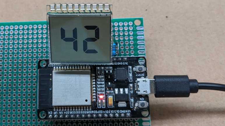
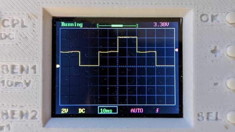
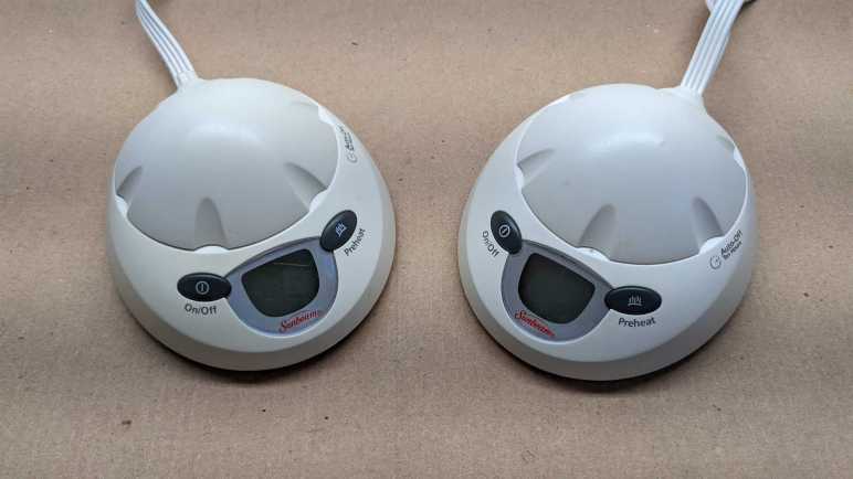
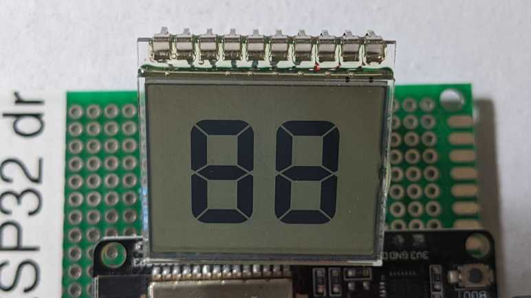
I now have imperfect but working control of a 2-digit 7-segment LCD module salvaged from a Sunbeam PAC-215 electric blanket controller. I used an ESP32 for this initial run because I thought I needed voltage control over all ten pins. After a little bit of experimentation, I’ve found that I could probably get away with using 0V and 3.3V directly on each of the segment pins. For the common pins I need an additional option of the midway point 1.65V, but if it is true that an LCD uses very little current, perhaps I could supply that voltage with merely a voltage divider built from resistors? If true, I might be able to control this with something far simpler and less powerful than an ESP32. Perhaps an ATmega328 (Arduino)? Or a PIC16F18345, which has a DAC peripheral and already on hand. (If I’m going to buy a chip, I’ll take Joey Castillo’s suggestion and buy one with LCD control peripheral built in.) These are potential experiments for the future. For now, I want to wrap up work with this particular pair of salvaged LCDs which means leaving good notes for my future self.

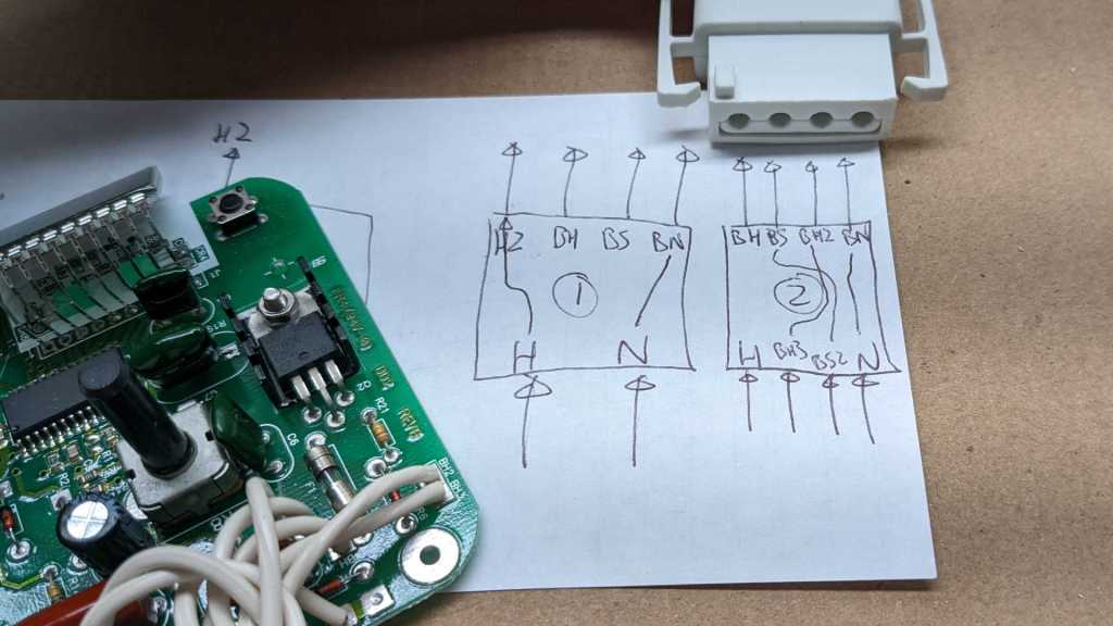
I scribbled down this diagram when probing the pins. The pins were numbered before I knew what they did. Now that I know which are segment and which are common, I could label them differently.

I also moved to a zero-based counting system thinking it might be easier to match up to code. Color-coding the different common pins is an idea I picked up from Joey Castillo’s slides, but I wonder if that’s the best way to go. I can’t claim to be an expert on how to use color in a way that’s still accessible to the color blind, and coding common pin information in color risks losing data for scenarios like printing on a black-and-white laser printer.

Moving to letters for segments and numbers for common allows me to put them together as labels on each segment while reducing ambiguity. This is also friendlier to black-and-white printing, but it loses the visual delineation of color coding. Is this better? I don’t know as I see strengths in each. I couldn’t make up my mind on which to keep so I’ll keep both of these diagrams here as references for later.

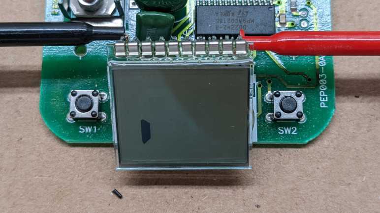
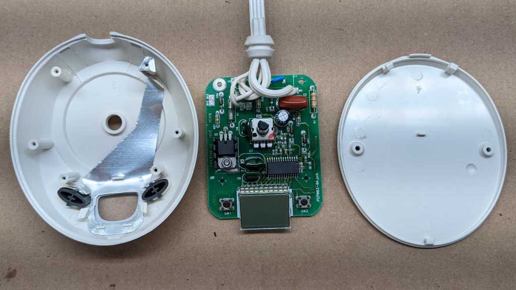
With this successful milestone of working with LCD modules, I revisited a module that frustrated me earlier.

ESP32 as Driver for Simple Segmented LCD

Once I have some confidence that I can write ESP-IDF code to control voltage levels at a speed relevant for driving a LCD, it was time to move beyond a simple breadboard test circuit. Onward to a perforated prototype board for all ten pins of a simple 2-digit 7-segment LCD, salvaged from an electric blanket controller. In the interest of keeping the wiring simple, I chose ten GPIO pins on one side of this ESP32 dev module I’m using (*) so I could wire everything (almost) parallel.

A 1kΩ resistor connects each ESP32 GPIO pin to an LCD pin, and a 330pF capacitor connects each ESP32 GPIO pin to ground. It isn’t quite a straight shot of ten parallel pins, with a two-wide gap on the left (serial communication TX/RX pins) and a single pin gap on the right (GPIO2, which this dev board connected to a blue LED that I’m using as a system heartbeat indicator.) On the far right is a loop of wire connected to the ground plane, so I have a convenient place for my oscilloscope to clip onto.

That completes the hardware side for my initial test. Moving on to my ESP-IDF project, I started hard-coding a sequence of LEDC PWM duty cycle adjustments that would drive this LCD in a fashion that I believe is called 1/2 duty, 1/2 bias. I think 1/2 duty means switching off between two common segments so each set of segments has 1/2 of the time, and 1/2 bias means the inactive common pin is held at 1/2 of the voltage difference of the active pins. I’m still a beginner so that might be wrong!

I chose to hard code the test because it avoids all the lookup table code I’d have to do if this were to become an interactive changeable display. I have two number digits to work with, so my test pattern is a Hitchhiker’s Guide reference.

The result is clearly legible at the optimal viewing angle, but it fades off quite a bit as the perspective changes. I remember a much wider range of legible viewing angles in its original use, I assume it means I’m doing something different from real LCD driver circuits in this little hack. Possibly related is the observation that, if I illuminate this screen from behind with a LED, its light washes out the LCD.

The original device used two LEDs behind the LCD for backlight, and it didn’t make the digits hard to read, so there’s definitely something missing in my amateur hour LCD controller. But the fact remains it is under ESP32 control, and I learned a lot on my way here. This was the first tangible result of a lot of fumbling around after listening to Joey Castillo’s Remoticon talk on hacking LCDs. Seeing “42” show up on screen is a good milestone to stop and review what I’ve learned.


Source code for this experiment is available on GitHub.

(*) Disclosure: As an Amazon Associate I earn from qualifying purchases.

Switching to ESP-IDF For PWM Waveform Control

I used ESPHome and Home Assistant to quickly experiment with parameters for ESP32 chip’s LEDC peripheral for generating PWM (pulse-width modulated) signals, seeing how they looked under a cheap oscilloscope. But for actually driving a segmented LCD, I will need even better control over signal behavior. It is an issue of timing: I need to toggle between high and low states for each common segment pin to generate an alternating signal, and I have two common segments to cycle through. In order to avoid flickering the LCD, this cycle needs to occur at least several tens of times a second.

The tightest control over timing I could get with ESPHome appears to be the on_loop automation, which is generally triggered roughly every 16 milliseconds. This translates to roughly 62Hz which, if I could complete the entire cycle, would be sufficient. But performing all of those toggles within a single on_loop would be too fast for our eyes to see, so we can only take one step in the cycle per on_loop. In order to toggle both high and low on consecutive on_loop, that cuts me down to 31Hz. Then there are two common segments, which cuts it further to 15Hz. I need something faster.

Until I have other tools in my toolbox, the “something faster” I have on hand require going to Espressif’s ESP-IDF SDK. PlatformIO makes ESP-IDF easier to work with, and I’ve had experience with this arena. My starting point (chosen because I’ve done similar things before) is to write a FreeRTOS task dedicated to toggling voltage levels by changing PWM parameters. In between steps of the cycle, I use a FreeRTOS wait (vTaskDelay) to send this task into the background until the next step. This mechanism allows finer control over timing than the ~16ms of on_loop, though it is only slightly better at 10ms by default. Repeating the math above, that works out to 25Hz which would at least be as good as 24fps film. But that is not the limit. Once I’m working within ESP-IDF, I have the option to get even finer timing control. I can get a little bit faster by reconfiguring FreeRTOS tick rate via ESP-IDF’s menuconfig tool. And for ultimate timing control I can start working with hardware timers.

I whipped up a test program to generate a staircase pattern. From 0% duty cycle, to 50% duty cycle, to 100%, then 50%, and repeat with 0%. Running at 20ms per step in the cycle, the timing looks solid. I can easily move this to 10ms and still have a solid square wave.

The 50% PWM value looked almost good enough without a capacitor. (Left) I have a huge pile of 300pF capacitors on hand, so I tried one and the waveform looked much better. (Right.) This is good enough for me to move forward with wiring this signal into a segmented LCD.


Source code for this experiment is available on GitHub.

Quick ESP32 PWM Experiment via ESPHome

I’ve mapped out the segments of a small LCD salvaged from an electric blanket controller. I activated these segments with an ESP8266 that alternated between 0V and 3.3V on two GPIO pins. Good for individual segments, but not good enough to drive the whole display. There are eight segment pins and two common pins for 8*2=16 total possible combinations (14 of which are used for the two 7-segment digits) controlled from ten total pins.

Technically speaking, an ESP8266 has enough GPIO pins, but we’d start intruding into the realm of sharing pins between multiple tasks which is more complexity than I wanted to tackle for a quick test. When driving a LCD, we also want to control voltage levels on these pins and ESP8266 lacks hardware PWM peripheral. For these reasons I will use an ESP32. It has more than enough pins, and hardware PWM peripherals to support generating a voltage on all those pins. ESP32 LEDC PWM peripheral is very flexible, and I need to determine how I want to configure that peripheral.

I used ESPHome because it is a great platform for quick experiments like this. I don’t strictly need WiFi here, but easy integration to Home Assistant and ability to update code over the network are great conveniences. Before I found ESPHome, I would wire up a few potentiometers to the circuit board and write code to use ADC to read their positions. A bit of code will then allow me to interactively play with parameters and see their results. But now, with ESPHome in my toolbox, I don’t need to solder potentiometers or write code for ADC. I can get such interactivity from the Home Assistant dashboard.

By default, ESPHome configures LEDC PWM peripheral to run at a frequency of 1kHz. According to Espressif documentation, it can be configured to run as high as 40MHz, though at that point it really isn’t a “PWM” signal anymore with only a fixed 50% duty cycle. Slowing down the frequency increases the number of bits available for duty cycle specification, and I wanted to find a tradeoff that I think will work well for this project. Here is an excerpt of ESPHome configuration YAML I used for this test.

output:
  - platform: ledc
    pin: GPIO23
    id: pwm_23
  - platform: template
    id: pwm_freq
    type: float
    write_action:
      lambda: |-
        int newFreq = (int)(10000000.0*state)+1000;
        id(pwm_23).update_frequency(newFreq);
    
light:
  - platform: monochromatic
    gamma_correct: 1.0
    output: pwm_23
    name: "PWM23"
  - platform: monochromatic
    gamma_correct: 1.0
    output: pwm_freq
    name: "PWM Freq"

This allows me to adjust two variables, each exposed to Home Assistant as a monochromatic dimmable light. Which I can change via a slider on a web page instead of a potentiometer soldered to the board. (The gamma correction value was set to 1.0 because we’re not actually controlling a visible light that requires gamma correction.)

  1. pwm_23 controls the PWM duty cycle.
  2. pwm_freq controls the PWM frequency via ESPHome Template Lambda. Theoretically from 1kHz to 10MHz, though in practice we won’t reach either end as the state never gets all the way down to 0.0 nor all the way up to 1.0.

As I adjusted the frequency, ESPHome automatically calculates the duty cycle bit depth.

[15:32:00][D][ledc.output:041]: Calculating resolution bit-depth for frequency 2491148.000000
[15:32:00][D][ledc.output:046]: Resolution calculated as 5
[15:32:00][D][ledc.output:041]: Calculating resolution bit-depth for frequency 2494322.000000
[15:32:00][D][ledc.output:046]: Resolution calculated as 5
[15:32:00][D][ledc.output:041]: Calculating resolution bit-depth for frequency 2497869.000000
[15:32:00][D][ledc.output:046]: Resolution calculated as 5
[15:32:00][D][ledc.output:041]: Calculating resolution bit-depth for frequency 2501411.000000
[15:32:00][D][ledc.output:046]: Resolution calculated as 4
[15:32:00][D][ledc.output:041]: Calculating resolution bit-depth for frequency 2503623.000000
[15:32:00][D][ledc.output:046]: Resolution calculated as 4
[15:32:00][D][ledc.output:041]: Calculating resolution bit-depth for frequency 2505428.000000
[15:32:00][D][ledc.output:046]: Resolution calculated as 4

From this snippet, we can see that 2.5MHz is the limit for 5 bits of resolution. 25 = 32 levels, which gives me control of resulting voltage in (3.3V / 32) ~= 0.1V increments. I think that’ll be good enough.


Here are some plots in oscilloscope form: First the starting point of 50% duty cycle at default 1kHz frequency, before and after adding a 100nF capacitor into the mix.

Not nearly good enough to output 1.65V. To make this better, I can increase the capacitance or increase frequency. Increasing capacitance will dull system response (and I need pretty quick response to rapidly cycle between LCD common pins) so I start cranking up the frequency.

At hundreds of kilohertz without capacitor, the resulting wave is more than what this little oscilloscope can capture at this timescale. When the 100nF capacitor is added in, we see a pretty respectable 1.65V signal, might even be good enough. But there’s plenty of room left to go faster.

Getting into the megahertz range, there’s enough natural capacitance in the system (wires, breadboard, etc.) that we see a pretty good waveform even without a real capacitor in line with the output. But with just a 330pF capacitor (much smaller than the 100nF I started with) the resulting voltage looks pretty good. At least, at this time scale. Now I need to move beyond ESPHome for better control of 2.5MHz PWM signals.

Electric Blanket LCD

I chose to take apart controllers from my old broken electric blanket because I got frustrated trying to control LCD from a food thermometer and went looking for something simpler. I was optimistic that an electric blanket controller, with just two 8-segment digits, would be just the ticket.

I was so eager I performed a quick LCD test before I even completed the teardown. I got a single segment to show up, which was a promising start. I was also happy to see this LCD connected to its circuit board with nice long metal pins that I could unsolder, not the elastomeric “zebra strip” used by the food thermometer. These pins are even spaced in a breadboard-friendly 0.1″ pitch, win!

I recently got the Engineer solder sucker from Adafruit, upon Helen Leigh’s recommendation and it made this de-soldering task much easier than with my previous lowest-bidder solder sucker. I now recommend the Engineer unit too, it is well worth the price premium.

I tried to put this module directly into a breadboard, but the pins are too fragile. (They would bend instead of pushing into the breadboard.) Thanks to the 0.1″ spacing, it was very easy to solder robust headers onto those pins.

The headers gave me a solid reliable connection to those pins, making it easy to map out all the segments. Far easier than the food thermometer LCD and its elastomeric strip. Now I need to figure out how to generate the voltage levels necessary to drive this LCD.

Electric Blanket Control (Sunbeam PAC-215)

Electric blankets are an energy-efficiency way to stay warm during cold nights. If I’m going to stay in bed while sleeping, why heat the whole house? Heat just the bed and get a comfortable rest. But they don’t last forever, and this particular Queen-sized blanket stopped heating for unknown reasons. I’m going to take apart its two control units (one for each half of the bed) to see what’s inside.

According to the label, this is a Sunbeam PAC-215 STYLE 85KQP with a maximum power draw of 360 watts. I interpret PAC-215 to mean the functional designation and 85KQP to mean a specific cosmetic variation, but that’s just a guess. (And it doesn’t affect a teardown, anyway.)

Peeling back all the adhesive circles unveiled two Philips-head fasteners.

Once those two fasteners were removed, there were three plastic clips to undo before the bottom could be separated from the enclosure. We see many thick traces and wires of through-hole components. Four small Philips-head fasteners hold the circuit board in place, the larger fifth fastener is for the heat sink and can be left in place.

In addition to those four fasteners, the LCD is held by two plastic clips and blobs of hot glue.

Once removed, we could separate the circuit board from the enclosure. Curiously, I see a sheet of metal glued to enclosure top conducting from one of the four screws out to the front of the display area. It might be for grounding purposes, but there is no other metal for it to make contact. It’s not obvious to me what user scenario justified this effort.

I was amused to see that backlight for the LCD is just a pair of LEDs soldered to the board. Simple, straightforward, and functional. No fancy multi-layer light diffusers for this screen.

The circuit board has a white silkscreen marking of PEP003-0A.pcb on the left and a copper marking of FR4(94V-0) DD2 REVB on the right. This picture was rotated 180 degrees relative to earlier pictures to better read identifier on the large surface-mounted IC.

DD2ZW2-3
MP9ACO218E
KOREA

I can make out the ST logo but a search for “DD2ZW2” and “MP9ACO218E” on their site both came up empty. Based on the traces going directly to the LCD, this chip has LCD control capabilities. How much more? I don’t know. It might be a complete electric blanket controller solution for all I know. The other item with a ST logo is a BTB06 triac.

I then proceeded to disassemble the other controller, whose enclosure came apart the same way. I had expected to find two different circuit boards: a primary controller with majority of logic and a secondary unit purely for user interface purposes. I was wrong: the two circuit boards are identical. They only differ in how wires were soldered to each board. I followed their paths and drew a crude diagram.

The power plug enters the first unit and connected to points labeled “H” (Hot) and “N” (Neutral). These are forwarded to the second unit as H2 and BN, respectively. H2 enters the second unit at its own “H” and BN goes to the second unit’s “N”.

Outputs of the first unit are labeled BH and BS, which enters the second unit as BH3 and BS2, respectively, and forwarded on to exit points BH2 and BS. The second unit’s own output goes out as BH, and neutral is forwarded out to the blanket plug.

The blanket plug itself was interesting. It was made of injection-molded plastic and designed to allow loose tolerances due to the flexible nature of the plastic yet still offer lots of mechanical strain relief.

The story continues inside, with plenty of strain relief considerations. This should nearly eliminate any mechanical stress from acting on the four crimped electrical connectors.

This teardown was more interesting than I had expected, as the controllers were more sophisticated than I had given them credit for. That was fun in its own right. But the motivation for doing this teardown today (instead of later) was so I could get my hands on some simple bare LCD modules I could play with.