ESP32 VGA Signal Generator Finds Cozy Home Inside Monitor

I want to repurpose a malfunctioning monitor as a lighting fixture. I was tempted to separate the LED backlight from the LCD module, because that LED illumination is the functionality I actually cared about. But I might need the LCD portion for further diagnostics, so I held off separation for now. Either way, I need an ESP32 generating VGA signal of full screen white to keep the monitor from going into sleep mode. Dangling it outside the monitor is functional, but not very elegant. There’s plenty of space inside the monitor enclosure for a little ESP32 development board, I just have to find places to solder the necessary wires.

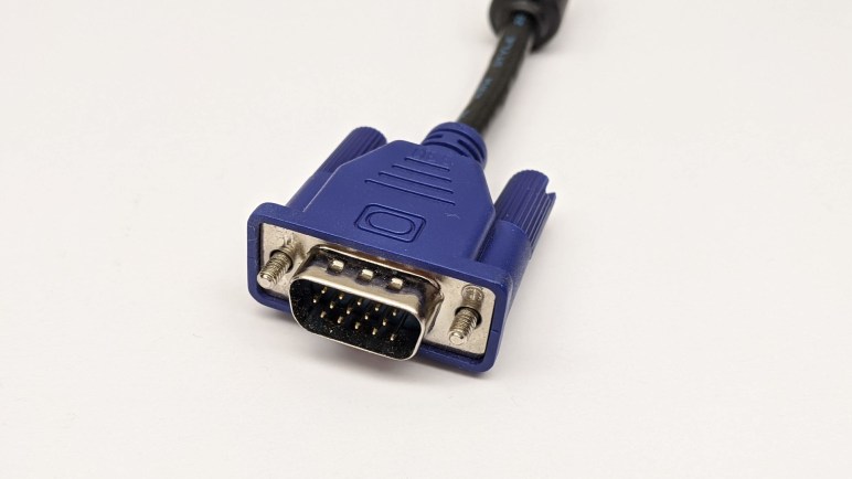
The signal output side is easy because we know where the VGA input port is. There was no exposed metal to solder on the top side, but it is a through-hole part so soldered pins are accessible from the bottom. A multimeter set to continuity detection mode quickly found the five critical signal pins I need to solder to: red, green, blue, horizontal sync, and vertical sync.

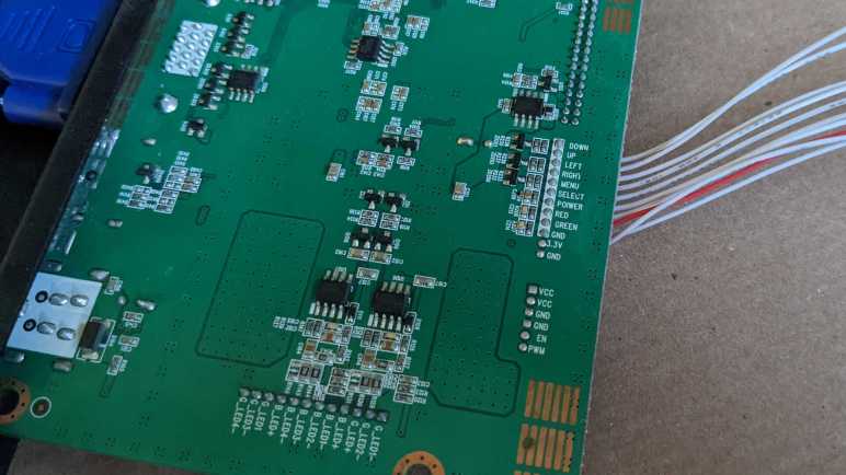
I also probed the VGA ground pins and found them to be common to electrical ground throughout the entire board, so that would be easy. The only remaining challenge was to find an appropriate power source for the ESP32. I found the power supply input jack, but that comes in at 24V DC and too high for the ESP32’s onboard voltage regulator. I didn’t want to add a buck converter to the circuit because I’m sure something already existed on this board. The answer was found on the connector for physical control buttons for this monitor. We see a row of wires each corresponding to a button: Down, Up, Left, Right, Menu, Select, Power. Below that are wires for the two status LEDs: red and green. And finally, GND and 3.3V, which I could tap to power my ESP32.

With these wires soldered in place, the ESP32 will have power as soon as the monitor is plugged in, eliminating the need for a separate power supply. It will generate a VGA signal sent directly to the VGA input port, eliminating the need for a separate VGA cable. When the power button is pressed, the monitor will wake up and detect a valid VGA signal and display full screen white, turning the monitor (and its useless sub pixels) into a lighting fixture.

Small black heat-shrink tubing helped me keep the wires organized, and a large clear heat-shrink tube encased the ESP32 board providing electrical insulation from the monitor enclosure. A small piece of double-sided tape holds the entire assembly inside the monitor. It lives here now. This lets me test the concept and verify the system could run long term in this state. If proven successful, I will return and separate the LED backlight to unlock full brightness.

Full Screen White VGA Signal with Bitluni ESP32 Library

Over two and a half years ago, I had the idea to repurpose a failed monitor into a color-controllable lighting panel. I established it was technically feasible to generate a solid color full screen VGA signal with a PIC, then I promptly got distracted by other projects and never dug into it. I still have the weirdly broken monitor and I still want a large diffuse light source, but now I have to concede I’m unlikely to dedicate the time to build my own custom solution. In the interest of expediency, I will fall back to leveraging someone else’s work. Specifically, Bitluni’s work to generate VGA signals with an ESP32.

Bitluni’s initial example has since been packaged into Bitluni’s ESP32Lib Arduino library, making the software side very easy. On the hardware side, I dug up one of my breadboards already populated with an ESP32 and plugged in the VGA cable I had cut apart and modified for my earlier VGAX experiment. Bitluni’s library is capable of 14-bit color with the help of a voltage-dividing resistor array, but I only cared about solid white and maybe a few other solid colors. The 3-bit color mode, which did not require an external resistor array, would suffice.

I loaded up Bitluni’s VGAHelloWorld example sketch and… nothing. After double-checking my wiring to verify it is as expected, I loaded up a few other sketches to see if anything else made a difference. I got a picture from the VGASprites example, though it had limited colors as it is a 14-bit color demo and I had only wired up 3-bit color. Simplifying code in that example step by step, I narrowed down the key difference to be the resolution used: VGAHelloWorld used MODE320x240 and VGASprites used MODE200x150. I changed VGAHelloWorld to MODE200x150 resolution, and I had a picture.

This was not entirely a surprise. The big old malfunctioning monitor had a native resolution of 2560×1600. People might want to display a lower resolution, but that’s still likely to be in the neighborhood of high-definition resolutions like 1920×1080. There was no real usage scenario for driving such a large panel with such low resolutions. The monitor’s status bar said it was displaying 800×600, but 200×150 is one-sixteenth of that. I’m not sure why this resolution, out of many available, is the one that worked.

I don’t think the problem is in Bitluni’s library, I think it’s just idiosyncrasies of this particular monitor. Since I resumed this abandoned project in the interest of expediency, I didn’t particular care to chase down why. All I cared about was that I could display solid white, so resolution didn’t matter. But timing mattered, because VGAX output signal timing was slightly off and could not fill the entire screen. Thankfully Bitluni’s code worked well with this monitor’s “scale to fit screen” mode, expanding the measly 200×150 pixels to its full 2560×1600. An ESP32 is overkill for just generating a full screen white VGA signal, but it was the most expedient way for me to turn this monitor into a light source.

#include <ESP32Lib.h>

//pin configuration
const int redPin = 14;
const int greenPin = 19;
const int bluePin = 27;
const int hsyncPin = 32;
const int vsyncPin = 33;

//VGA Device
VGA3Bit vga;

void setup()
{
  //initializing vga at the specified pins
  vga.init(vga.MODE200x150, redPin, greenPin, bluePin, hsyncPin, vsyncPin); 

  vga.clear(vga.RGB(255,255,255));
}

void loop()
{
}

UPDATE: After I had finished this project, I found ESPVGAX: a VGA signal generator for the cheaper ESP8266. It only has 1-bit color depth, but that would have been sufficient for this. However there seem to be a problem with timing, so it might not have worked for me anyway. If I have another simple VGA signal project, I’ll look into ESPVGAX in more detail.

VGA Signal Generation with PIC Feasible

Trying to turn a flawed computer monitor into an adjustable color lighting panel, I started investigating ways to generate a VGA signal. I’ve experimented with Arduino and tried to build a Teensy solution, without success so far. If I wanted full white maybe augmented by a fixed set of patterns, Emily suggested the solution of getting a VGA monitor tester.

They are available really cheaply on Amazon. (*) And even cheaper on eBay. If I just wanted full white this would be easy, fast, and cheap. But I am enchanted with the idea of adjustable color, and I also want to learn, so this whole concept is going to stay on the project to-do list somewhere. Probably not the top, but I wanted to do a bit more research before I set it aside.

One thing Emily and I noticed was that when we zoomed in on some of these VGA monitor testers, we can tell they are built around a PIC microcontroller. My first thought was “How can they do that? a PIC doesn’t have enough memory for a frame buffer.” But then i remembered that these test patterns don’t need a full frame buffer, and furthermore, neither do I for my needs. This is why I thought I could chop out the DMA code in the Teensy uVGA library to make it run on a LC, keeping only the HSYNC & VSYNC signal generation.

But if I can get the same kind of thing on a PIC, that might be even simpler. Looking up VGA timing signal requirements, I found that the official source is a specification called Generalized Timing Formula (GTF) which is available from the Video Electronics Standards Association (VESA) for $350 USD.

I didn’t want to spend that kind of money, so I turned to less official sources. I found a web site dedicated to VGA microcontroller projects and it has tables listing timing for popular VGA resolutions. I thought I should focus first on the lowest common denominator, 640×480 @ 60Hz.

The PIC16F18345 I’ve been playing with has an internal oscillator that can be configured to run at up to 32 MHz. This translates to 0.03125 microseconds per clock, which should be capable of meeting timing requirements for 640×480.

I thought about leaving the PIC out of the color signal generation entirely, have a separate circuit generate the RGB values constantly. But I learned this would confuse some computer monitors who try not to lose data. So we need to pull RGB values down to zero (black) when not actively transmitting screen data. It would be more complex than just focusing on HSYNC/VSYNC but not a deal breaker.

[UPDATE: I continued this project with an ESP32.]


(*) Disclosure: As an Amazon Associate I earn from qualifying purchases.

Sparklecon 2020 Day 2: Arduino VGAX

Unlike the first day of Sparklecon 2020, I had no obligations on the second day so I was a lot more relaxed and took advantage of the opportunity to chat and socialize with others. I brought Sawppy back for day two and the cute little rover made more friends. I hope that even if they don’t decide to build their own rover, Sawppy’s new friends might pass along information to someone who would.

I also brought some stuff to tinker at the facilities made available by NUCC. Give me a table, a power strip, and WiFi and I can get a lot of work done. And having projects in progress is always a great icebreaker for fellow hardware hackers to come up and ask what I’m doing.

Last night I was surprised to learn that one of the lighting panels at NUCC is actually the backlight of an old computer LCD monitor. The LCD is gone, leaving the brilliant white background illuminating part of the room. That motivated me to dust off the giant 30-inch monitor I had with a bizarre failure mode making it useless as a computer monitor. I wasn’t quite willing to modify it destructively just yet, but I did want to explore the idea of using the monitor as a lighting panel. Preserving the LCD layer, I can illuminate things selectively without overly worrying about the pixel accuracy problems that made it useless as a monitor.

The next decision was the hardest: what hardware platform to use? I brought two flavors of Arduino Nano, two flavors of Teensy, and a Raspberry Pi. There were solutions for ESP32 as well, but I didn’t bring my dev board. I decided to start at the bottom of the ladder and started searching for Arduino libraries that generate VGA signals.

I found VGAX, which can pump out a very low resolution VGA signal of 160 x 80 pixels. The color capability is also constrained, limited to a few solid colors that reminded me of old PC CGA graphics. Perhaps they share similar root causes!

To connect my Arduino Nano to my monitor, I needed to sacrifice a VGA cable and cut it in half to expose its wires. Fortunately NUCC had a literal bucketful of them and I put one to use on this project. An electrical testing meter helped me find the right wires to use, and we were in business.

Arduino VGAX breadboard

The results were impressive in that a humble 8-bit microcontroller could produce color VGA signals. But they were not very useful in the fact that this particular library is not capable of generating full screen video, only part of the screen was filled. I thought I might have done something wrong, but the FAQ covered “How do I center the picture” so this was completely expected.

I would prefer to use the whole screen in my project, so my search for signal generation must continue elsewhere. But seeing VGAX up and running started gears turning in Emily’s brain. She had a few project ideas that might involved VGA. Today’s work gave a few more data points on technical feasibility, so some of those ideas might get dusted off in the near future. Stay tuned. In the meantime, I’ll continue my VGA exploration with a Teensy microcontroller.