The use of threaded rods to hold the Luggable PC case together was borne out of necessity: The print volume of the 3D printer is much smaller than the volume of a PC case so it must be printed in pieces then fastened together. A threaded rod provides strength along its length, but how do we best handle the inevitable corners?
The key constraint is the strength of a 3D printed part, especially the adhesion between layers. This is an unavoidable fact of life for FDM-type printers: the part is weakest between layers, so designing for 3D printers must consider the layers similar to how designing for wood must consider the grain.
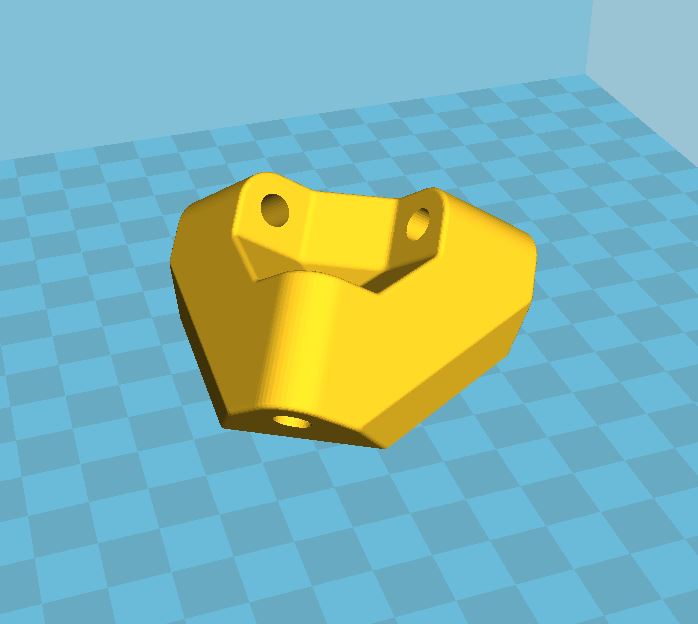
Version 1: basic asymmetric
In this design (as used in the “Easel PC” iteration) two of the rod axis are aligned with the direction of the layer. Stress along those two axis would mostly be held in check by the strength within each layer, but a fraction of the force would try to push the layers apart. To guard against this, the third axis is orthogonal so its fastening nuts would also try to hold the layers together.


The problem with this design is that the corners are asymmetric by nature. Not just in appearance, the loads it can tolerate are also asymmetric.
Version 2: symmetric but space consuming
The goal of a corner that handle loads symmetrically across the plastic layers means finding a way to make sure the plastic grain is equally strong across all three axis. The solution is to print at an orientation that lies at the same angle to all three axis.
While this design solved the problem of symmetric appearance and strength, it introduced a new problem: by printing this way, the hinge consumes a lot of the enclosed volume making it unusable. When the goal is to pack the computer components inside a minimalist PC case, every cubic centimeter counts!
This hinge was used in the “Threaded Rod Box V1” and the space it consumed severely hampered the packaging of that layout. It is definitely not the optimal solution so the search continues.
Version 3: Let’s All Huddle Close!
The previous two designs both depended on the plastic to take some part of the load and hold on to a few steel rods. These rods were a few centimeters apart because we needed room for a wrench to tighten the nuts. We needed the nuts to sit inside the corner because…
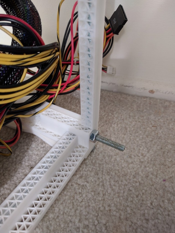
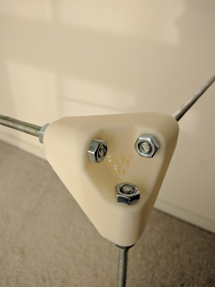
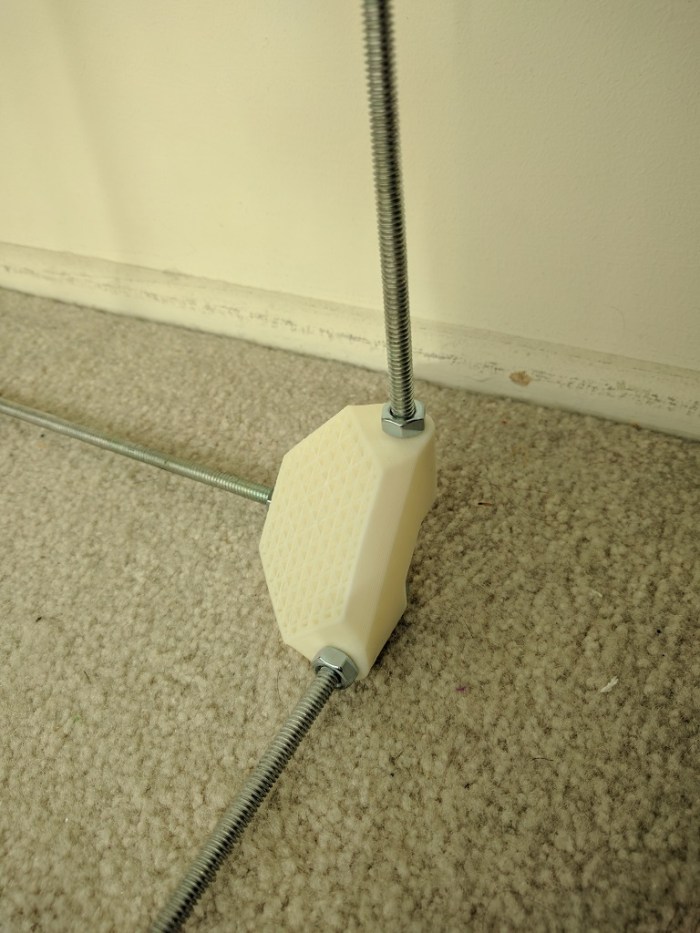
… um, why do we need them inside? The key for version 3 is the realization that we don’t need that. By offsetting the rods slightly, we can extend the rods past the corner so the fastening nuts are outside of the enclosed volume and not competing for space with the components inside the box.
When the nuts (and the required wrench clearance) are no longer inside the volume, it allows the rods to sit much closer to each other. Now the closest distance between rods are measured in millimeters instead of centimeters. It also means the three sets of fastening nuts help exert a clamping force across all three axis, compressing everything together. This compression means the alignment of the print layers become much less critical allowing significantly more freedom in designing the rest of the case.
This corner design was used successfully in Threaded Rod Box V2 as shown. (In these pictures, some of the threaded rods have yet to be trimmed to length.)