Supercon 2017 Badge – Pan Base is Turning

After the mechanical bits were assembled yesterday, I worked on the simple PIC program I’d need to drive it. This involved refining the exploratory code into something that resembles an usable device. Things like no longer running on a fixed program but read the potentiometer I wired into the circuit to dictate motor control. Fortunately most of the hard work is done by MPLAB X boilerplate code, I only had to weak a few things here and there to end up with the functionality I want.

(The MPLAB X project file is publicly available on Github.)

I also 3D-printed the remaining layers of the enclosure – the battery tray, a minimalist lid, and the little flexible clips that hold them all together. The layers are an extremely tight fit because the wiring plugs were longer than I expected. Right now they’re pressed against the bottom of the battery tray which is not good for connector health. I’ll increase the height for the next iteration to give everything more headroom.

Pan Base Assembled

The good news is that everything runs. The bad news is that it doesn’t run very well. I dug a digital camera with a built-in time-lapse mode, set it on top of the base, and shot a few clips. The jittery motion of this cheap DIY pan base is very clearly visible in the resulting video. There’s a reason professional photography pan heads cost a lot of money – they have much smoother bearings and better motors for fine control.

Since the conference kicks off tomorrow, I’m going keep forging ahead with what I have. No time to find better motors or bearings. There are a few issues that I might be able to fix in the PIC software, but the sticky jittery motion from the motor and bearing isn’t something I expect to be able to fix in code.

Well, I can hope the jittery motion is not visible in the default 128×96 resolution of the camera!

Supercon 2017 Badge – Pan Base Mechanical Assembly

Hackaday Superconference 2017 kicks off tomorrow! Clock is ticking for me to complete my preparation work. My 3D printer is hard at work churning out iterations of my motorized base for panning photo/video. I had originally intended to drive the whole works with my three-cell lithium lion battery pack built from cells salvaged from a Dell laptop battery pack. The battery power will go straight to the power coils of the stepper motor and a voltage step-down converter will reduce the voltage for the ULN2003 chip driving the steppers and my PIC16F18345 running a program to run the works.

The stepper motor is designed for nominal operating voltage of 5 volts, but the actual limit on stepper motor operation is the amperage running through its coils. I thought I could drive the coils with pulse-width modulation and keep the power under control. The batteries power is about 12 volts, so a 40% duty cycle should be a good approximation.

But real life got in the way of my plan with these unipolar stepper motors. As the coils are energized and de-energized in the PWM cycle, magnetic field and electrical current were getting sent elsewhere in the motor in ways I didn’t understand. Causing the motor to behave erratically instead of just turning at a lower power.

If there wasn’t a looming deadline, I would hit the web searches to learn and understand what’s going on so I could fix the problem correctly. But I do have a deadline and needed a quick fix. “Just” running the motor at full power isn’t a solution. The motor could run at ~12V but it gets very hot. If I was only using the motor to turn infrequently, this might be OK. But a camera pan base is constantly turning slowly.

In order to keep the coils energized with a lower voltage, I changed the power supply to a 4-pack of NiMH AA batteries. Their nominal voltage of 4.8 is close enough for my purposes. It is smaller and lighter than the Li-Ion pack and also eliminates the need for the voltage regulator. The trade-off is a drop in power capacity… which may or may not be important. We don’t know yet. I guess I should pack a NiMH battery charger.

Once the stepper motor power was sorted out, I added a potentiometer to give manual control of rotation direction and speed. Once I finish 3D printing a case around this, I will have a minimal implementation of the mechanical base.

Pan Base Mechanicals

Supercon 2017 Badge – Time Lapse Pan Base

It’s Wednesday and a concrete plan is way overdue if I want to make a project for Supercon 2017 this coming weekend. The badge is a little digital camera so I started thinking about camera accessories that I could build. Since I won’t have the camera itself until Friday, ideally the accessory has some baseline functionality that I can build before I get the badge itself.

There are tons of accessories for photography, but when the goal is to find something both electronic and mechanical, that narrows down the list. Browsing through a photography catalog, I considered a few accessories and settled down on one thing: a pan base. Useful for taking panoramic photos or time-lapse videos, it boils down to a little mechanical platform to turn the camera at a controlled rate as it does its thing.

And most importantly: I can build something basic by this weekend and build upon it through the weekend as time and progress allows. This incremental development means if I don’t get to them all, I’ll still have something neat to show off. This minimizes the risk I’ll get to the end of the weekend and have absolutely nothing to show.

Phase 1: Base Mechnicals

Build the electrical and mechanical parts of the pan base. Digging through the boxes of parts on hand, I think I have everything I need to build the base itself: I have a small slow stepper motor, an associated controller board, a thrust bearing for everything to spin on, and batteries. A PIC with a simple program should be enough to drive the controller board for a slow photography panning motion.

Pan base parts

Hopefully I can get it all put together by Friday, ideally with manual control so it can run by itself.

If this is all I could do, it should be enough to put the camera badge on top and turn on video recording mode for a video that pans across the field of view.

Phase 2: Camera Time-Lapse Mode

If I get the mechanical base working on its own before Friday, it’ll give me time to dive into writing the software for the camera. I’ll need to understand the sample code enough to know what pieces I need to copy/paste to build a time-lapse video app for the camera. Hopefully it’s as simple as taking the video recording application and slowing the frame-rate down.

Once I know the code necessary to gather images and put them in a sequence, I’ll worry about creating the UI to control things like time-lapse speed.

If this is all I could do, it’ll be enough to create cool time-lapse panning video clips to enter into the video contest.

Phase 3: Camera+Base Integration

This is the stretch goal in case everything above was easy and smooth (ha!): Integrate the camera and the base so the time-lapse application controls the panning base. The UI will allow control of not only the frame rate, but also the rotation speed as the time-lapse runs. The camera badge already has a simple API for I2C communication, so I’ll probably have to write code to talk to the PIC controlling the stepper motor via I2C. Either that, or have the PIC32 on board the camera talk to the stepper motor board directly. Whichever is easiest to get running by the end of the weekend.

If I can get this far, I can feel proud at what I have accomplished over Supercon 2017.

Let’s see how far I get. It’s time to get to work!


Supercon 2017 Badge – Pivot for Project Risk Reduction

The calendar does not lie – it is now Tuesday and Superconference starts Friday. After a day of playing with mTouch on the Curiosity board, I’m no closer to a project that captures my fancy. Time to take off the curious explorer hat and put on the project manager hat. (Assuming that it’s not already too late to do so…)

The fact is that I won’t have the camera badge hardware in my hands until Friday. Despite all the help Microchip tries to give us with libraries for doing mTouch, capacitive touch is finicky and will require tuning. On top of having to get oriented with the rest of the hardware. On top of the rest of the conference going on over the weekend. I don’t want to be so consumed by the project that I miss out on interesting things happening.

I’m sure there are hardware hacker types who has accumulated enough skills and experience to put together something in a short time. I have ambition to build up to that skill level, but I have to accept the fact that I’m not there today. And I’m probably not going to get there by the end of the week. Time to change the focus to something more predictable and less risky for the sake of getting something up and running this weekend rather than risk having nothing at all by the end of the weekend.

The new ideals:

  • External components interface with the camera badge in some way to add to the camera badge functionality.
  • External components do not require the camera badge itself for its basic functions, so I can start building it and debugging it before I get the badge Friday.
  • Integration with camera badge to be kept as simple as possible.
  • Integration should not be “none” – it’d be pointless to build something that works just as well without the camera badge.
  • Even if all integration efforts fail (at worst, integration is “none”) I want to have enough to demo the idea even if it doesn’t work.

The above ideas led me to think about building an electro-mechanical camera accessory. The gears in the brain continue turning…. but soon physical gears will turn, too.

GearBase1

Microchip “Curiosity” Development Board and its Zero Ohm Resistors

When I purchased my batch of PIC16F18345 chips, Microchip offered 20% discount off standard price for its corresponding Curiosity development board (DM164137). I thought it might be interesting and added it to my order, but I hadn’t pulled it out of its packaging until today.

Today’s motivation is the mTouch button built onto the board. As part of my investigation into projects I might tackle with the Hackaday Superconference 2017 camera badge, I found that the capacitive touch capabilities of the MCU is unused and thought it might be interesting to tie it into the rest of the camera badge. Before I try to fabricate my own touch sensors, I thought it’d be a good idea to orient myself with an existing mTouch implementation. Enter the Curiosity board.

Looking over the board itself and the schematics on the user’s guide, I noticed a generous scattering of zero ohm surface-mount resistors. If I had seen zero ohm resistors in isolation, I would have been completely mystified. Many electronics beginner like myself see a zero ohm resistors as something that does nothing, take up space, and there’s no point. For those beginners, a web search would have led them to this StackExchange thread, possibly the Wikipedia article, or maybe the Hackaday post.

Curiosity Zero OhmsBut I was not introduced to them in isolation – I saw them on the Curiosity board and in this context their purpose was immediately obvious: a link between pins on the PIC socket and the peripheral options built on that board. If I wanted to change which pins connected to which peripherals, I would not have to cut traces on the circuit board, I just had to un-solder the zero ohm resistor. Then I can change the connection on the board by soldering to the empty through-holes placed on the PCB for that purpose.

This was an illuminating “Oh that makes sense!” introduction to zero ohm resistors.

Maytag Top Load Washer (LAT8826AAM) Lid Switch + Fuse Module

Today’s distraction came courtesy of aging appliance. Specifically, the 20+ years-old Maytag top-loading clothes washer stopped working this morning. It has just started doing a load of heavy laundry that was out of balance and shut down when the tub started shaking. This itself has occurred before, we just had to redistribute the load and restart. Except this time pulling the knob failed to restart the machine. There was no sign of life, not even the power “ON” light.

Given that the machine acted as if it had no power, I first checked the house circuit breaker, verified the machine was plugged in, the easy things. After the simple checks were out-of-the-way, I started looking for a circuit breaker or a fuse built into the machine. A web search turned up several mentions of the lid switch which I initially ignored. During normal operation, an open lid would prevent the wash cycle from starting, but the power “ON” light would still be on. Since that light was dark, I had decided the lid switch couldn’t have been the problem.

That was the wrong decision.

The lid switch is actually a module that included the switch and a fuse. This fact didn’t sink in until I found this page, which described how to test continuity with a multimeter and cautioning that improper switch module installation may blow the fuse inside the module.

I removed the lid switch module from my washing machine, tested with my multimeter, and confirmed it was not behaving as it should. I am annoyed that Maytag did not design the fuse to be easily replaced. The whole module had to be replaced as a single unit: it was held together by fasteners that were clearly not intended to be removed. While I had the tools to remove them, it is a permanent removal.

Maytag Lid Switch

Once opened, the fuse was quickly found. The red arrow in the picture below points to a black piece (now broken in two pieces) that looks and feels like plastic but is electrically conductive.

When intact, this piece of fuse material holds the “LINE” terminal always in contact with the “MACHINE” terminal. When the washer lid is open, there is continuity between “NEUT”(RAL) to “MOTOR”. When the washer lid is closed, “NEUT” loses its connection to all other terminals, but “MOTOR” is put in contact with “LINE” and “MACHINE”.

The narrow neck of the fuse material is now broken, which also broke the usually always-on contact between “LINE” and “MACHINE”. When the washer lid is open, none of the terminals have continuity with any other terminal. When the lid is closed, “MACHINE” is in contact with “MOTOR” but that doesn’t do any good as “LINE” is disconnected.

Maytag Lid Switch Fuse

Now that I know how the module incorporates a fuse in addition to the lid switch, it was easy to rig up a quick test to see if the rest of the machine works. A successful test gives me the confidence a replacement module will bring the washing machine back up and running safely.

The next question is why the black piece broke. Was it from old age (innocent) or because there was a problem causing excessive amperage flow (worrisome)? The multimeter found no obvious short on the washing machine. And since the machine has been working for more than two decades, age is a plausible explanation. I’ll try the replacement module first. If the fuse blows again, I’ll have to dig deeper.

[2021 UPDATE: the washing machine has been running well for years after this replacement.]

SevenStock 20

Today was SevenStock 20 and I attended with my RX-8 in her BB-8 Halloween costume. Last year I attended SevenStock with the costume only partially completed. This year it is complete but a little faded from running around over the past year under SoCal sunshine. It was still plenty distinctive in the row of RX-8 lined up in the show & display area. Many people took pictures, some even took me up on my hint and posted on Instagram tagged with #rxbb8.

Out of all the cars on display, the one that stood out to me was ironically not a rotary-powered vehicle at all. It was a Mazda R360, Mazda’s first car built in 1960. By modern standards an adorable tiny little thing. It was on display at the Mazda corporate area along with other Mazda vehicle currently on the market. Which meant the little 1960 Mazda was utterly dwarfed by the modern Mazda SUVs on display.

Mazda R360 Next To Current Mazda SUVs

There were many powerful speed machines on display, but I kept coming back to admire the little R360 that can barely reach highway speed. There are four seats in the car but I don’t see how four adults can fit in this little box. It looked closer in size to a kid’s Power Wheels car!


SevenStock takes place on the infield of the Auto Club Speedway and the track itself was open during the event for people who paid a fee and can pass safety inspection. There was a sizable contingent who love the idea of driving out on the oval but for one reason or another passed on the high-speed track time.

This year the organizers tried an experiment: a “parade lap” to get a taste of driving on a banked oval via a bit of token track time. The thundering herd was led by the trio of historical rotary-power race cars brought by Mazda, and we stopped a few times on track for the scattered pack to organize. Here’s a picture taken during one of the on-track stops.

Rotaries On Track

The price of admission for the “parade lap” was $15, and I thought it was well worth it for the novelty value of taking my car on a real high-speed track. Even if we were only going at city-street speeds.

Reading the PIC32MX1XX Datasheet As A PIC16F18345 User

A review of the Hackaday Superconference 2017 “camera badge” hardware provided adequate orientation but no lightning strike of project inspiration. Today I did find the project page for last year’s Supercon badge as well as a summary page of some things people have created with the 2016 badge. People have done some really cool things with that badge serving as foundation. I’m feeling intimidated but also determined to keep trying to see what I can devise.

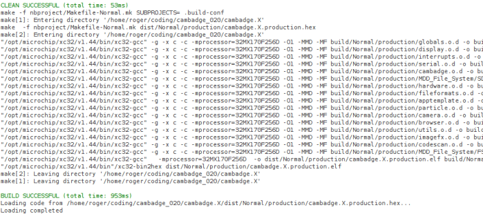
Today’s tactic: Dive into the data sheet for the Microchip control unit at the heart of the 2017 badge, the PIC32MX170F256D. No matter what else happens, it would be good to have an overview of what the chip can and can’t do. I was also hoping that a review of the data sheet will unveil something about the chip that would inspire a project. Since I’ve already read the PIC16F18345 data sheet back-to-back, I hoped the familiarity with Microchip conventions will give me a head start.

The first surprise was the size (length) of the data sheet. Only 344 pages when the much simpler PIC16F18345 chip had a 491 page document. It didn’t take long for me to figure out why, since every feature section started the same way: a disclaimer that the data sheet was only the summary and tells me I need to do more reading if I want the details.

OnlyASummary

Well, that explains the size! For my purposes today, it’s no big deal. In fact it is helpful since the summaries mean I don’t have to press “Page Down” as often.

There are some comfortable commonality with the PIC16F18345 I’m familiar with: Timers and comparators. Digital I/O and analog input (ADC.) Communication via SPI, I2C, UART. And all these peripheral modules are mapped into a memory space so everything is accessed via memory reads and writes. And finally: a big focus on power management.

There are some differences that I might miss in the PIC32MX1XX:

  • PWM seems to have gone missing, unless there is a much more advanced component that can serve similar purposes but I don’t recognize it as such.
  • I/O pins are much less powerful. The PIC16F can handle up to 50mA on any single I/O pin and up to 250mA total. The PIC32MX can only handle 15mA per pin with 200mA total.
  • Narrower voltage range: Unlike the super flexible and relaxed PIC16F that is happy to run with anything from 2.3V to 5.5V, the PIC32MX prefers to stay within 2.3V to 3.6V. The maximum is listed as 4.0V, so it might be dicey to run this thing on a single rechargeable lithium cell – the nominal voltage is 3.7V but a fully charged cell might be up to 4.2V.

The PIC32MX uses a different instruction set (MIPS32 M4K) and that’s no surprise. I expect to be mostly isolated from this fact by writing in C and letting the XC compiler worry about the instruction set. The PIC32MX also requires more support circuitry. Whereas the PIC16F can literally connect directly to a battery and it’ll start running. Again I’m mostly isolated in this case because the camera badge is already built for me and all the support components are already on board.

And now, on to the things that might be interesting. I started with the title description: “32-bit Microcontrollers (up to 256 KB Flash and 64 KB SRAM) with Audio and Graphics Interfaces, USB, and Advanced Analog

The first thing to catch my eye: USB, backed by this promising-sounding bullet point on the cover page: “USB 2.0-compliant Full-speed OTG controller“. USB OTG would let us plug-in USB peripherals and greatly expand the possibilities of what we can do. Alas, my hopes were dashed when page 2 clarified that USB OTG is only on the PIC32MX2XX series and absent on the PIC32MX1XX we have on the camera badge. So that’s out.

The “Advanced Analog Features” bullet items seem to mostly center around support for capacitive touch sensing, mostly around their “mTouch” design. Since their reference implementation involves copper traces and plates on a printed circuit board, that won’t be directly applicable to me. But perhaps this type of support circuitry can be hacked into something fun.

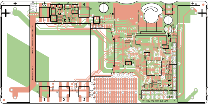
I have yet to explore the world of audio electronics, so sadly the audio interface features are mostly gibberish to me. I had higher hopes for the “Graphics Interfaces” side of that claim and… I came up empty-handed. There’s nothing that obviously said “graphics” to me on the feature set. The closest thing I can find is the PMP (Parallel Master Port) peripheral which is good for talking to display panels, and is indeed already employed on the camera badge to drive the 128×128 OLED screen.

So in the category of “stuff that the chip can do, but isn’t already being used” the best candidate at the moment is the analog circuitry to support capacitive touch. Since I don’t have time for a OSH Park PCB, it’ll have to be something creative. Perhaps something as primitive as taping down loops of wire to cardboard or 3D-printed plastic parts.

The gears in the brain keep churning…
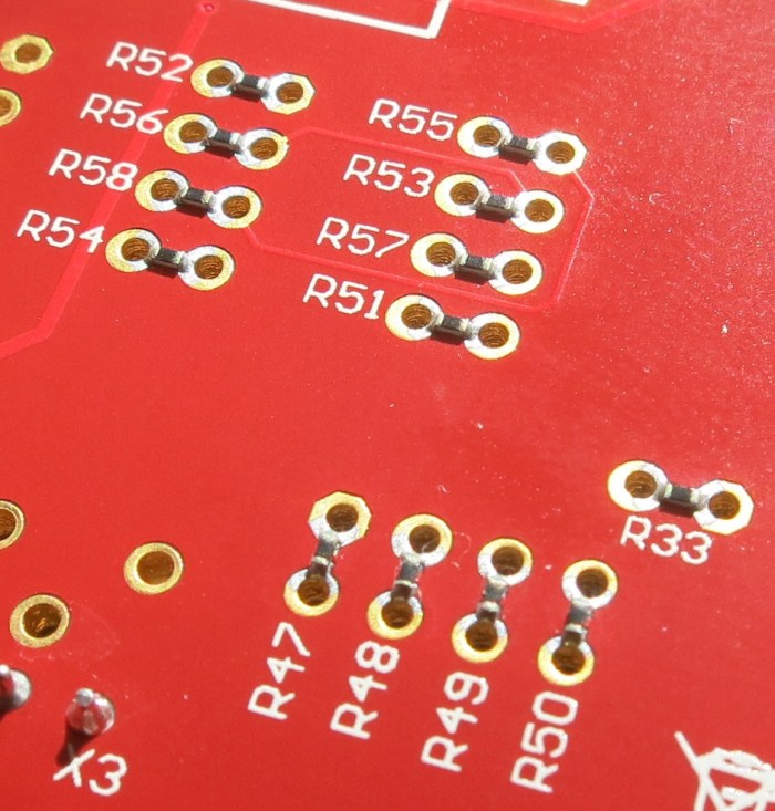
 

Supercon 2017 Badge – Hardware Orientation

Today was spent getting orientated on the hardware components making up the camera badge for Supercon 2017. The starting point is the project documentation’s “hardware description” page, which gave a basic overview that helps me decide where I want to dig deeper.

2413581507673490011

The CMOS sensor at the heart of the OV9650 camera module claims to support up to 1280×1024 resolution, which isn’t bad for such an inexpensive component. The sample image posted on the project file section, however, is only 128×96 resolution. It’s not immediately clear where >99% of the pixels disappeared to or how feasible it’d be to bring them back.

Perhaps that resolution was chosen to match the OLED screen, which has 128×128 pixels of resolution controlled by a SSD1351 chip. If this is the case, and more pixels can be captured from the camera with minimal effort, that opens up project ideas such as having the little screen pan across a larger image. (a.k.a. the Ken Burns effect.)

We have multiple tiers of storage that makes different capacity/speed trade-offs. First we have some space for data on the PIC itself, then we have a Microchip 23LC1024 serial RAM, and finally a microSD card.

There’s an LIS2HH12 accelerometer on board which might enable some cool projects, though I’m struggling to think up one that captures my fancy. Maybe in a bit.

The chip that orchestrates all of this is a PIC32MX170F256D. Fortunately for me, I already had the tools on hand to develop for it thanks to my time playing with the PIC16F18345. They’re very different chips, but since they’re both from Microchip I would write code to both using the same MPLAB X IDE albeit with different C compiler underneath: XC8 vs XC32. The PIC32 is set up to run a .hex file off the microSD card, so it’s not necessary to have a PIC programmer. But if I need to flash at a more direct level, the board has headers to connect the same PICkit 3 programmer I use for the PIC16F18345.

All in all, a decent set of hardware. Now I just need to think of a really cool project to do with it all.

Supercon Badge – Initial Exploration

Supercon 2017 is coming up soon and I now have a ticket to attend. Part of the fun is the badge which, unlike SIGGRAPH or WestTec, is not a printed piece of paper. In the case of Supercon (and a few similar conferences) it is actually a circuit board with some functionality. The Supercon 2017 badge is a very minimal low resolution digital camera. Why would we want such a thing when most of us carry cell phones with far superior cameras? Because it is only the start: conference attendees are invited (expected?) to use it as a starting point and build something cool.

Which means I have only about 10 days to do my homework – what would I build with the badge? As a first-time attendee I’m not sure what to expect. Last year I saw brief glimpses of the badge under construction, but I didn’t see any of the projects built by conference attendees.

Well, with any project, the first step is to look for documentation. The official source of information is, naturally, the camera badge’s own project page on Hackaday.io. I felt intimidated on first look: my own adventures in electronics hardware hasn’t covered anything to do with cameras, OLED panels, or the like. About the only thing I am vaguely familiar with is the microcontroller at the heart of the device. It is a Microchip PIC, though from their PIC32 series which is higher-end and more capable than the PIC16F chips I had been playing with.

Fortunately, it uses the same MPLAB X IDE for development. I had to download and install the XC32 compiler corresponding to the PIC32 chip, but that was relatively easy. After changing the path separators from the author’s Windows machine (‘\’) to the Ubuntu I’m working on (‘/’) the project builds successfully.

That’s a good start. The next step is to go digging through the code base and look for something interesting for me to do.

cambadgebuild