Mounting Z-Axis 12V Power Supply

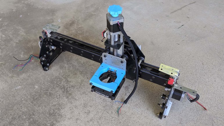
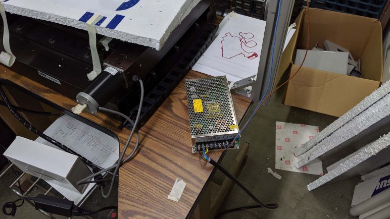
Wiring was never my favorite part of a project, but it needed to be done. A lot of it at that. After the latest plotter test, I picked up the next item on the to-do list: the 12V power supply for Z-axis. It was just set on the table for testing the second and third iteration of Z-axis, held only by gravity which meant it started shifting position and threatened to fall off the edge when the XY stage movement hit the table’s resonance and everything started shaking. We should mount it rigidly on some part of this machine.

My first thought was to 3D print a bracket for this power supply, and mount it to one of the aluminum extrusion beams. But then I thought it would make more sense to put it alongside X and Y axis control boxes which are combination power supply and stepper driver modules. I’ll mount the Z-axis power supply here, but I’ll hold off moving the stepper drive here as well since that would involve re-routing many more wires.

CNC 12V PSU mounted on plate below

I drill three holes in the metal panel mounted below the table for X and Y axis driver modules. Even after the 12V power supply was bolted in place, there’s plenty of room left on this panel for the Z-axis stepper driver in the future, and possibly also the ESP32 control board. This is the eventual destination for all electrical components, but one step at a time. Of course, it would help if I don’t keep changing parts of the machine

Pen Plotting With Third Iteration Z-Axis

After third iteration of CNC Z-axis was installed, we wanted to perform a simple test. This particular assembly already had brackets to hold a spindle of some kind. We don’t know what it used to be, but measuring the hole we infer it was approximately 65mm in diameter. We didn’t have a suitable cutting tool on hand, so we reverted back to the old standby: testing it as a pen plotter.

We didn’t have any 65mm diameter pen, either, but we do have plenty of plastic bits in the form of failed and abandoned 3D prints. A few blocks were fished out of the bin and took up space so we could clamp a pen in the spindle holder. A pen could not reach the surface of the XY table, so a cardboard box and a few sheets of foam were used to raise the working surface. It’s not precise by any stretch of the imagination, but it’ll suffice for a pen plotting test.

The test plot was the ~25 minute variant of a Sawppy portrait. This file previously helped us determined UGS was not going to work in this particular configuration, and that bCNC worked better. Now we’ll feed this G-code throub bCNC to plot with the new Z-axis holding a pen.

Since the pen was clamped rigidly in the holder, and the work surface was crude with boxes and foam, the paper was not level. For one side of the sheet, the pen barely made enough contact to draw. On the opposite side, it dug deeply enough to start damaging the paper. But it did not tear, so we’re calling it unintentional embossing.

The results looked pretty good! It’s a good confidence booster before I return to more housekeeping tasks of building this machine.

Integrating Transplanted CNC Z-Axis

Bolting on a transplanted Z-axis assembly gives us a screw driven linear actuator with open-loop control via stepper motor, plus a switch for finding home position. Electrically this assembly is identical to the belt drive assembly we had wired up earlier, this second round of electrical integration consisted only of crimping some connectors on new wires.

For hardware configuration, the first stop is always to punch in part numbers to see what we get. We can tell this stepper motor is in a standard NEMA 17 form factor, but we needed to search on its part number SM42HT47-1684B to discover specs such as maximum current per phase. (1.68A) We conservatively capped our driver to a low value of 1.0A just to be safe, leaving room to increase if we need to.

The steps per revolution for this motor was unstated, so we’ll start with the assumption 200 steps per revolution typical of such motors and adjust as needed. We then measured the lead screw on this Z-axis. Since everything else on this machine is metric, we used metric measurements and it appeared to be 2mm per revolution. This maps the motor neatly into 100 whole steps per mm.

A test run with whole steps sounded very rough, so we increased the stepping up to 4 microsteps and a corresponding adjustment in Grbl to 400 microsteps per mm. This gave us smoother movement at the loss of some holding torque. We won’t know if that loss would be a problem until we start putting some heavier tools on that spindle holder.

In the meantime, we’ll start testing the same way we tested the servo Z-axis: use it as a pen plotter. Only this time we’ll have a stepper controlled screw drive Z-axis.

A New Home For CNC Z-Axis

Our hacky CNC machine project upgraded to a real CNC Z-axis courtesy of a retired CNC router project. It was a modular design built out of extrusion beams and commodity M5 fasteners, which made it easy for us to remove the Z-axis and transfer it to our project.

The modular nature also made it easy to make modifications, and as we mounted this Z-axis on our machine we could see signs of creativity by the previous owner. We’re not sure exactly what problems all of these modifications were intended to solve, perhaps we will learn as we get further on this project. For now, the focus is on exploration which means a preference for nondestructive modification until we have a better idea of what we are doing.

HAKNC bracketWhich means we’re not going to drill into aluminum for mounting holes just yet, we’ll get started with a simple 3D printed bracket for mounting this Z-axis assembly on our gantry. We would prefer to have mount it just a little bit lower, bit we were hampered by the 3D printed limit switch mount. It may get replaced later, but for now it dictates our Z-axis mounting height.

Thanks to the use of flexible aluminum extrusion beams on both CNC projects old and new, mechanically speaking it was relatively painless to transplant this Z-axis from one machine to another. Now we proceed to electrical and software integration.

A New Candidate Z-Axis From Retired CNC

We didn’t get very far with a belt drive stepper Z-axis before another candidate emerged. This is the gantry of a CNC router table, with some sort of a spindle holder and two stepper-controlled axis. The Z-axis moving the spindle holder up/down, and one of the linear axis. X or Y I can’t tell. The other axis would roll on rails and controlled via belts missing from this picture.

There’s a name on the spindle holder, and a search for Inventables CNC found their current product called X-Carve which shows some superficial similarity to what we have before us. But this one showed signs of several modifications by its previous owner. We do not have the full history of it, we just knew it was a CNC project that was left behind several months ago when its owner moved to a different city. It was given to another person, who then offered it to us because we were likely to make use of it immediately on our project.

And use it we shall, because that Z-axis looks a lot better than the one we were ready to start exploring. This Z-axis module uses a leadscrew, which we expect to offer superior precision (good) at a loss of top speed (probably less important for Z axis.) It was originally designed to be a CNC Z-axis, built with aluminum extrusion beams far more rigid than the thin folded sheet metal construction of our belt-drive assembly. Our belt-drive sheet metal Z-axis was the X-axis of a Monoprice Mini Select 3D printer, which meant it was not designed to take the kind of loads that would be necessary for CNC cutting anyway.

Let’s mount this modified Inventables Z-axis and make it work instead.