After I finished wiring the strain gauge array for a load cell, I pulled the bundled circuit board out of its anti static bag. According to the product listing, this is built around a HX711 amplifier and analog-to-digital (ADC) converter. All that information I read earlier about putting excitation voltages into a Wheatstone bridge to interpret small changes in strain gauge resistance? All that magic is done inside this chip.
The bundle included some classic 0.1″ pitch pins to solder to the circuit board, but I thought I had a better idea. I pulled out my JST-XH connector kit and used the six-position wire-to-board unit for my strain gauge array connection. JST-XH is polarized to help ensure I don’t plug it in backwards. However, it is bigger than plain unadorned headers so it didn’t fit with the surface mount components already on the board, requiring that I mount it to the flat backside instead.
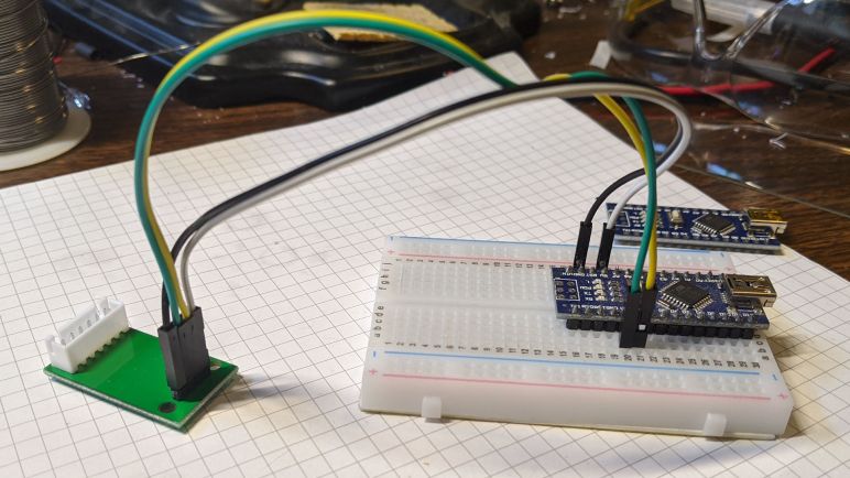
I didn’t perform the same JST-XH replacement for the digital data connection, because I wanted the flexibility to use jumper wires to connect this board to something I can use to read data from a HX711. Looking around for software libraries online, I found a HX711 library for Arduino so I pulled out my prototyping breadboard with an Arduino Nano already on board. This is as good of a starting point as any.
Four jumper wires were needed: power, ground, data, and clock. The hardware is ready to go, so I switched gears to software and today’s little plot twist of PlatformIO.
