As I combed through ESP32 documentation for information on its PWM capabilities, I realized there was something missing from what I expected to see: information on which physical pins are associated with these PWM peripherals. This was something I saw and learned to expect from reading documentation for other microcontrollers like the PIC16F18345. When I read about a peripheral, it is always accompanied by a chart showing which physical pins are wired to that peripheral. But not the ESP32.
The reason became obvious as I started browsing ESP32 peripherals, a list that just kept going on and on and on. There are so many features on this chip for doing so many different things, how can we possibly use them all? Well, sadly, we can’t. Only a small fraction of this chip’s internal capabilities can be routed to the limited number of external pins. So this chip can do many interesting things, but it can’t do them all at the same time.
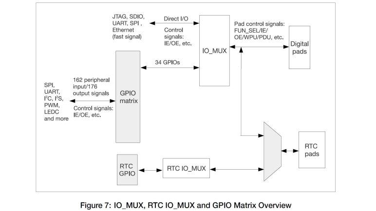
The key documentation here is the ESP32 Technical Reference Manual. (PDF) Section 5 talks about the GPIO matrix, which is what we configure when we write an ESP32 application using GPIO peripherals. According to this document, all the ESP32 peripheral inputs added up to 162 potential signals, and all the outputs added up to 176 output signals. The GPIO matrix is how we control which of those 338 (!!) pins are routed to the 34 physical pins actually available on an ESP32. I found it amazing that, by definition, we could only use ~10% of an ESP32’s input/output capabilities.
And in reality, we are even more constrained than that. Especially when working with a ESP32 DevKit module as I am. The physical appearance of 38 pins are a little misleading, because there are multiple ground pins (all tied together, at least on my board) and both input and output voltage of the onboard 3.3V regulator. Six pins are tied to onboard flash memory and thus not available for use, and given the fact they are unusable I’m puzzled why they even broke them out on the dev kit. The UART for uploading programs are also exposed, meaning a few more pins unavailable for projects. Then there are pins involved in the boot and firmware upload process, and those involved in JTAG debugging.
I found it all very confusing, but thankfully I found an ESP32 GPIO reference chart by Random Nerd Tutorials which I consider a great resource for navigating this particular jungle. According to this chart, there are only 15 GPIO pins that an be used without caveats. Four more are limited to input-only and lack internal pull-up or pull-down resistors. Roughly 4-6 more pins are available depending on my appetite for adventure and confidence, followed by their associated restrictions. The rest might as well have been marked “HERE BE DRAGONS” and I’m staying away from them for my micro Sawppy brain project.
