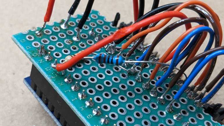
I’ve been talking to the Sanyo LC75883 LCD driver chip on a Honda CD control panel by soldering wires directly to the board and running those signals to a breadboard. Once I found the correct connector to plug into that board, I transferred my (jumper wires and breadboard) experimental circuit to something a little more compact. But like all projects, it didn’t work at first and needed some diagnosis.
My first problem was a classic electronics problem: “Data In” and “Data Out” lines were reversed. This is a close cousin of the RX/TX problem, where we always have to figure out whose perspective a particular label is using. The RX (receive) line for one component needs to be wired to the TX (transmit) line of the other component, and vice versa. For my circuit, it meant “DO” on the connector pin 17 should go to the LC75883’s “DI” pin. I had connected “DO” to “DO” and “DI” to “DI” which does nothing until I swapped them.
After figuring out my DI/DO lines I was at parity with my breadboard circuit. Which is sufficient for controlling LCD output, but I just like before I still couldn’t read input. I examined the remaining pins looking for things I could try. First experiment was with pin 15, which was labeled D-GND which might mean “Digital ground”. I had been using the trio of pins labeled P-GND for my ground instead. I don’t have a good guess what “P” stood for, but if I had been using the wrong ground that might explain the odd behavior I observed. Sadly, tying D-GND to P-GND made no noticeable difference.

Looking down the list again, I decided to take another look at pin 19 labeled LCD-RST. There was a similar RESET pin on the Toyota tape deck faceplate. I had left that unconnected because the LC75853 driver chip on that board did not expose a reset pin so there was nothing to connect. Due to the similarities between these two chips, I thought I would do the same thing here. But I realized that was a mistake when I reviewed the LC75883 datasheet.
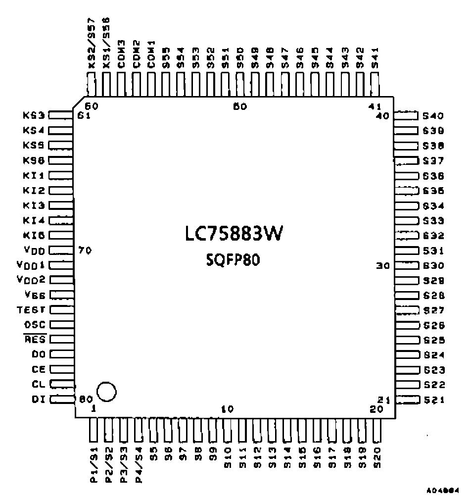
Unlike its sibling, this chip does expose a reset pin (76). Which meant I had been leaving reset unconnected and floating all this time. Not good! I soldered a 1kΩ resistor between pin 14 SWD-VDD and pin 19 LCD-RST in order to tie LCD-RST high, and after that, all input worked as expected. Turning the quadrature encoder knob no longer blanks out the screen at every other detent, and I could successfully read key scan report data to know which buttons had been pressed. And LCD output still worked just as before. This is great! I’m glad I figured out my mistake and frankly, I’m surprised this thing worked at all with a floating reset pin. That’s my silliest mistake so far with this project, the others weren’t as bad.
