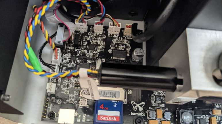
I turned on a broken FormLabs Form 1+ resin laser printer without its rear panel so I could poke around. I started with cables (POWER, X SIGNAL, Y SIGNAL) between its mainboard and galvanometer control board, because that’s where things broke. But now I have a better understanding (and even a long-shot idea to try) I came back to measure voltages of wires on the remaining mainboard connectors.
The Z-axis linear motion actuator (Z MOTOR) is driven by a bipolar stepper motor with two phases and two wires for each phase, the four wires labeled A+/A-/B+/B-. The resin tray peeling actuator (TILT MOTOR) is physically a very different motor but driven in the same style. Z-axis limit switch appears to be an optical interrupter which can be more accurate than the physical contact microswitch typically used for limit switch duty in FDM printers. It has three wires. One end has continuity to ground, the other end measured +5V while the printer is powered up. Middle wire measured 0.06V when Z-axis is positioned at top, and 3.7V when Z-axis is lowered.
As part of laser eye protection, the printer stops printing if we open the lid. Detecting this condition is the job of a (likely Hall effect) sensor just under the lid along with a magnet embedded in the lid. The magnet sensor plugs into the connector labeled INTERLOCK on the mainboard, with three wires colored black, blue, and red.
| Wire Color | Volts DC (No magnet) | Volts DC (Magnet nearby) |
|---|---|---|
| Black | 0V (Ground) | 0V (Ground) |
| Blue | 11.18V DC | 0.02V DC |
| Red | 11.18V DC | 11.18V DC |
Speaking of that laser, I had hoped to see a diode module with two wires positive and ground. (Example*) But LASER connector actually had four wires: red, black, blue, and yellow.
| Wire Color | Laser Standby | Laser Illuminated |
|---|---|---|
| Red | 11.18V DC | 11.18V DC |
| Black | 8.55V DC | 6.6V DC |
| Blue | 5V DC | 3.3V DC |
| Yellow | 0V (Ground) | 0V (Ground) |
I’m sure those voltages aren’t the whole picture so if I have the ambition to drive this laser module myself, I have more investigation ahead.
Next connector is BUTTON for a gorgeous illuminated metal button on the front panel. Four wires support this button, two for the LED and two for the switch. Red wire is LED+, gray wire is LED- (wired to ground on this circuit board.) Yellow is pulled up to 3.3V on this board and when pressed, yellow wire shorts to black which is wired to ground.
The final connector is a little more complex. It is a 10-pin (2×5) IDC ribbon cable for the front panel display. Probing that display will be a project all by itself.
(*) Disclosure: As an Amazon Associate I earn from qualifying purchases.

Hi Roger, it’s Annabel with Flashforge. I’m writing to check if you are interested in getting a Flashforge 3d printer for your future project development. Our 3d printers are known for their easy operation, rich function and reliable performance. If this is something you like, happy to discuss further details.
LikeLike
I have more than enough 3D printers for now, thank you.
LikeLike
Thanks for letting me know, Roger. Happy printing!
LikeLike