
Deciphering the circuit board from a Remington hair clipper was a relatively simple exercise in understanding how a circuit worked, so I followed it up with the circuit board from a Conair hair clipper teardown.

The functional requirements would have been the same: When the switch is on, use power from a set of nickel cadmium batteries to power a motor. When the switch is off, accept power from a DC charging adapter to charge nickel cadmium batteries, plus a red LED to show charging is in progress.


The execution, though, turned out to be very different. What caught my attention about this board during the teardown earlier was the absence of diode D3, and the motor’s negative terminal was connected directly to the battery negative terminal via a wire instead of the designated “M-” connection point on this circuit board. Probing component connections, I came up with this schematic:
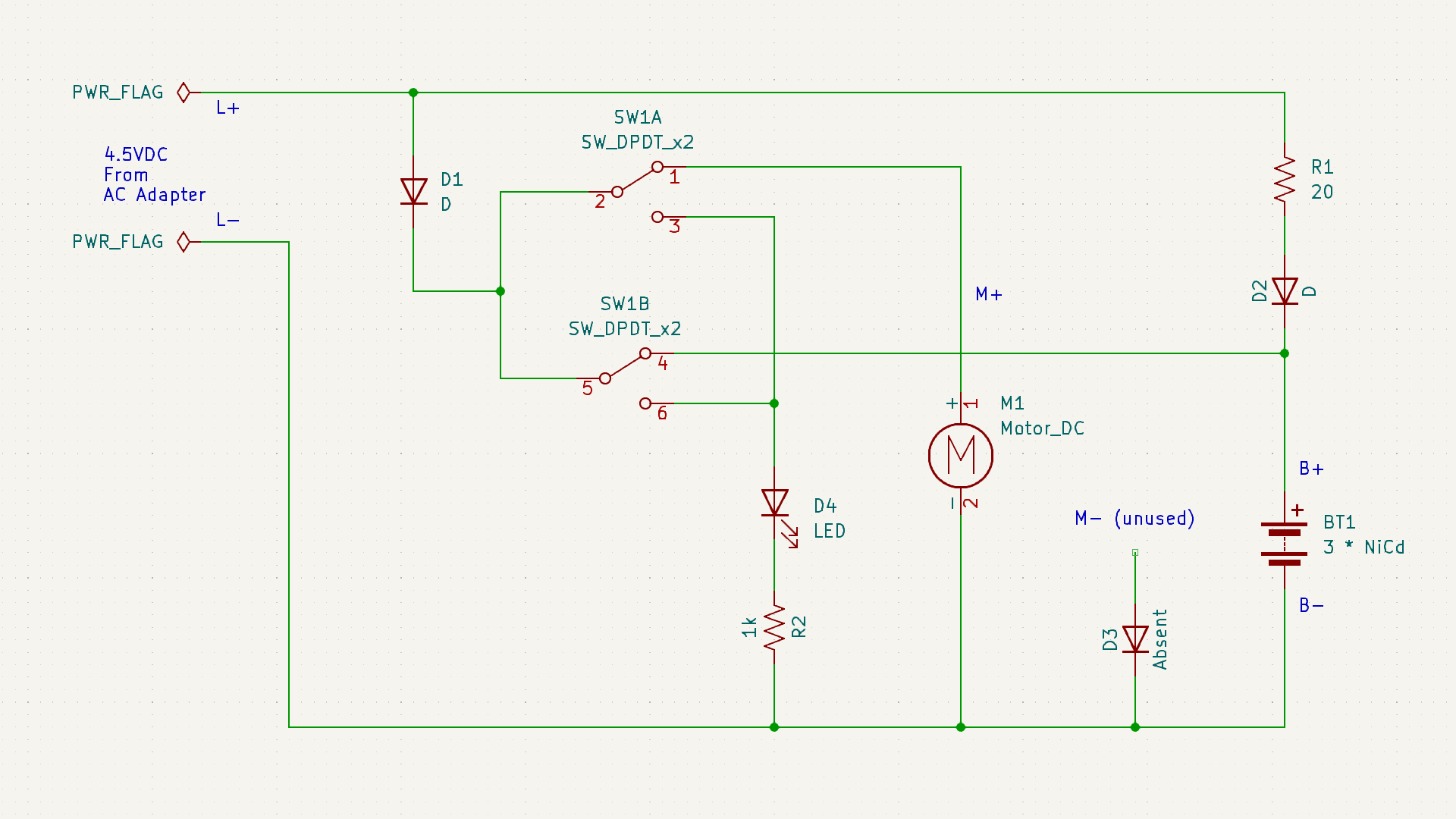
The absent diode D3 is directly connected to the unused M- terminal. My best guess was an intent to prevent the motor from sending reversing voltage into the battery pack, but that doesn’t seem like a very likely scenario in a hair clipper. Maybe they thought it was when they designed the circuit board, and then decided it was not a problem?
20 Ohm resistor R1 is in line with diode D2, leading to battery positive. This pair would only come into play when the device is charging. So D2 would be in charge of making sure the battery doesn’t feed back into charging port terminals L+/L-, and R1 performs some sort of voltage or current regulation for charging. The Remington clipper circuit board had a provision for such a resistor, but absent from my unit. Presumably they decided it was not necessary.
While D2 is in charge of making sure the batter doesn’t feed back into charging terminals while the switch is set to charge, D1 exists to do the same job when the switch is set to run motor. I found it interesting they decided against consolidating those two diodes into a single diode as Remington did. The difference between those two paths is R1, so the absence of its counterpart in Remington would be related in some way.
Charging indicator LED is in series with a current-limiting resistor R2. 1k Ohm would keep that LED pretty dim, but it doesn’t need to be particularly bright. The Remington clipper circuit board had a resistor in parallel with the LED whose purpose mystified me. There is no counterpart resistor here so it must not be intrinsic to hair clippers.
The most surprising detail was the path from battery positive to motor positive. Obviously that would be routed through the switch, but I didn’t expect to find that it was routed back through the switch a second time. This series path would double the electrical resistance added by the switch. In contrast, the Remington board runs motor power through the switch in parallel, halving the switch resistance. Why did Conair do it this way? The Remington approach made more sense given my level of knowledge.
Due to the relatively simple appearance of these two hair clipper control boards, I thought it would be easy to fully understand what they do once I captured their schematic. But as it turned out, they each have their own mysteries. I hope to eventually understand such things as I continue learning electronics design by reverse-engineering more circuit boards.
This KiCad learning project is publicly available on GitHub
