Single Cell Lithium-Ion Battery Management Module (4056) Schematic

After drawing up schematics of circuit boards salvaged from hair clippers for KiCad schematic practice, I decided to increase the difficulty with a single cell lithium-ion battery management system (BMS) module built around a 4056 chip. Since this is a popular module made by many vendors, I know publicly available schematics already exist. I don’t see my KiCad exercise as duplicate effort. I see those existing schematics as an answer key for me to check against!

In my earlier look, I found many chips from different vendors under the 4056 designation, all of which seem to be mostly compatible with each other. Since then, I’ve come across several pointers to NanJing Top Power’s TP4056. Either they were the first or they have been the most successful vendor of this solution. The modules I have on hand are not genuine TP4056, but one of the competitors marked 4056H.

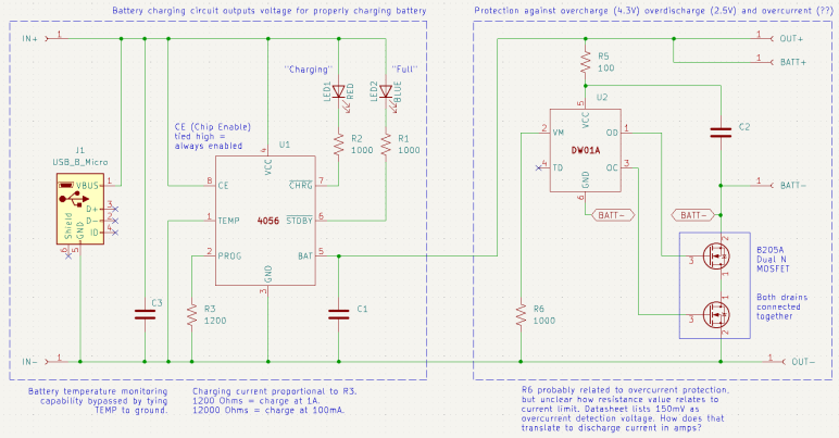
I was also unable to read any markings on component marked U2 before. Thanks to my new polarized light macro photography solution, I could now make out its faint markings as DW01A. This is a battery protection chip that guards against over-charging (cut off at 4.3V), over-discharge (cut off at 2.5V) and over-current (150mV? That doesn’t make sense.)

Armed with this information, I drew up my own schematic symbols for the 4056 chip and the DW01A. They’re probably available in a KiCad part library somewhere, but I wanted the practice with KiCad symbol editor. It took me a while to figure out how to label inverted pins. Eventually I found this KiCad forum thread telling me to put the name inside curly brackets and prefixed by tilde. So for the inverted STDBY pin I had to type in ~{STDBY}.

I ran into an ambiguity with surface-mount resistors on this board. There were several labeled with 102 (meaning 1K Ohm) or if I should read them upside-down as 201 (meaning 200 Ohm). In this case I was able to measure them at 1K Ohm but I won’t always have that luxury. How to I figure out which way is up?

I drew my schematic with dotted lines marking the two major feature areas: to the left is the battery-charging circuit driven by the 4056 chip, to the right is the battery-protection circuit under control of the DW01A chip. I traced through most of the 4056 side earlier, because I was looking to adjust charging rate and found I could do so by replacing R3 with resistor of a different value. This time I was more curious about the over-current protection side of the module. Looking at my schematic, I thought R6 would be a promising lead for current control, but at 1000 Ohms its resistance was far too high to be a current-sensing shunt resistor. Plus, it wasn’t in line with the load path. I didn’t understand how it could work or how it related to the 150mV current-sensing value listed in the DW01A data sheet.

Thinking I probably made a mistake in my schematic, I went online to check against others and it seems to match. One of those schematics was attached to this Electronics StackExchange thread, which also explained how over current protection works in this design. The details are a bit over my head, but supposedly works through the dual N-channel MOSFETs already present to handle over-charging and over-discharging. Sounds like the engineers behind DW01A were clever enough to get over-current protection without using a current-sensing shunt resistor, and that’s why I couldn’t find one. This is very interesting and I wished I was familiar enough with these components to fully understand how it works. Maybe I can come return to this topic later after I’ve learned more electronics.

What is clear to me, though, is that I wouldn’t be able to change the over-current limit by changing a resistor. I would have to find a dual N-channel MOSFET with different characteristics to trigger protection at a different limit. And if I want to do it on this board, I would have to find one with a footprint compatible with the 8205A chip used here. That would be a project well beyond the scope of today’s KiCad exercise so I set the idea aside and moved on.


This KiCad learning project is publicly available on GitHub

Conair Hair Clipper (HC318R) Schematic

Deciphering the circuit board from a Remington hair clipper was a relatively simple exercise in understanding how a circuit worked, so I followed it up with the circuit board from a Conair hair clipper teardown.

The functional requirements would have been the same: When the switch is on, use power from a set of nickel cadmium batteries to power a motor. When the switch is off, accept power from a DC charging adapter to charge nickel cadmium batteries, plus a red LED to show charging is in progress.

The execution, though, turned out to be very different. What caught my attention about this board during the teardown earlier was the absence of diode D3, and the motor’s negative terminal was connected directly to the battery negative terminal via a wire instead of the designated “M-” connection point on this circuit board. Probing component connections, I came up with this schematic:

The absent diode D3 is directly connected to the unused M- terminal. My best guess was an intent to prevent the motor from sending reversing voltage into the battery pack, but that doesn’t seem like a very likely scenario in a hair clipper. Maybe they thought it was when they designed the circuit board, and then decided it was not a problem?

20 Ohm resistor R1 is in line with diode D2, leading to battery positive. This pair would only come into play when the device is charging. So D2 would be in charge of making sure the battery doesn’t feed back into charging port terminals L+/L-, and R1 performs some sort of voltage or current regulation for charging. The Remington clipper circuit board had a provision for such a resistor, but absent from my unit. Presumably they decided it was not necessary.

While D2 is in charge of making sure the batter doesn’t feed back into charging terminals while the switch is set to charge, D1 exists to do the same job when the switch is set to run motor. I found it interesting they decided against consolidating those two diodes into a single diode as Remington did. The difference between those two paths is R1, so the absence of its counterpart in Remington would be related in some way.

Charging indicator LED is in series with a current-limiting resistor R2. 1k Ohm would keep that LED pretty dim, but it doesn’t need to be particularly bright. The Remington clipper circuit board had a resistor in parallel with the LED whose purpose mystified me. There is no counterpart resistor here so it must not be intrinsic to hair clippers.

The most surprising detail was the path from battery positive to motor positive. Obviously that would be routed through the switch, but I didn’t expect to find that it was routed back through the switch a second time. This series path would double the electrical resistance added by the switch. In contrast, the Remington board runs motor power through the switch in parallel, halving the switch resistance. Why did Conair do it this way? The Remington approach made more sense given my level of knowledge.

Due to the relatively simple appearance of these two hair clipper control boards, I thought it would be easy to fully understand what they do once I captured their schematic. But as it turned out, they each have their own mysteries. I hope to eventually understand such things as I continue learning electronics design by reverse-engineering more circuit boards.


This KiCad learning project is publicly available on GitHub

Remington Hair Clipper (HC-920) Schematic

After completing an upgrade for my workbench lighting solution, I went back to my most recently learned skill: drawing electronic schematics in KiCad. I’ve learned that skill once and lost it. I don’t want it to atrophy again after this second round. I want to practice with a few simple things and the top of my electronics waste pile is the circuit board from my Remington hair clipper (HC-920) teardown. Great, I’ll start with that!

When I looked over this board briefly, the absence of resistor R1 drew my attention. Instead of an actual resistor, this part of the circuit has a solder bridge on the back turning R1 into a zero Ohm resistor. How did this circuit work, and what role would a non-zero R1 have played?

After tracing through how the components are interconnected and drawing them out in a schematic, I’m no closer to an answer. (The dual-pole dual-throw switch is drawn in the “motor running” position.)

The easiest part to understand concern the red LED that indicates charging is underway. When the switch is in the non-running position, the LED receives power from the charging power adapter. R2 is a 390 Ohm current limiting resistor for the LED, which I expected. R3 is a 10K Ohm resistor parallel with the LED, which was a surprise. Why is R3 here? Drawing a bit of power away from the LED would have made it a bit dimmer, but if that’s the objective, it seems easier to increase resistance of R2 instead of adding another component to the board. I assume this design has been optimized to squeeze every penny out of production cost, so if R3 survived that process it must have some importance I don’t understand.

Terminals J+/J- provide 3V DC from the charging adapter. In parallel with the red LED, it passes through diode D1 to the battery. The diode makes sense to ensure battery power doesn’t feed back out to to the charging port or wasted on the red LED.

When the switch is in the running position, as shown in the schematic, the motor positive and negative terminals have continuity with battery positive and negative. It also has continuity with terminals J+/J-. Interesting, as this implies I could run the motor directly off the charging adapter if it was plugged in, turning this cordless hair clipper into a wired hair clipper. This would have been an option to run the clipper if the batteries had died. I don’t think I was aware of this capability and it didn’t even occur to me to try!

That leaves the mystery resistor R1, which runs between the batter negative terminal and J- terminal when the switch is in the non-running position. This implies R1 is involved in limiting charging voltage or current on the battery charging circuit. However, there was a black wire directly connecting battery negative to J-, which would have bypassed this resistor on the circuit board. And if we cut that wire the motor would have no way to receive battery power. Maybe I’ve made a mistake in my schematic, though I couldn’t find it if so. But if not, R1 makes no sense in this wiring arrangement. It must have been designed to support a different physical wiring arrangement. So given what we have here, it makes sense R1 is missing and bridged with a blob of solder.

I had fun with this, so naturally I wanted to do a compare-and-contrast with the circuit board from a Conair hair clipper I had also taken apart.


This KiCad learning project is publicly available on GitHub

Laptop Backlight External Power and Optional Polarizer

I have a salvaged LED backlight module that I intend to turn into my workbench light. The LCD pixel array itself is gone, I’m working with the backlight LED strip, associated light diffuser, the polarization film, and metal frame. I have the display circuit board as well, but I’ve chosen against interfacing with its onboard backlight LED controller and voltage boost converter in favor of the simpler solution of providing external power for the LEDs. My LED tester says I need to find about 32.2V DC to drive these LEDs at 20mA.

I rummaged through my bin of salvaged power supplies. I found this HP inkjet printer power supply CM751-60190 who previously helped with vacuum fluorescent display adventures. I measured its open-circuit output voltage at 31.8V DC. Perfect! This eliminates the need for a boost/buck voltage converter, and would drive the LEDs at a little under 20mA. Giving me a bit of safety margin because I’m not monitoring current draw as the real backlight controller does, and hopefully driving these LEDs at slightly under 20mA would extend their service life as well.

All six strings are wired in parallel to this power source, and it lights up quite nicely. Despite being a smaller panel drawing a tiny fraction of the power, it illuminates my workbench almost as brightly as the large Monoprice monitor thanks to the fact it isn’t working through multiple layers of LCD infrastructure: this was just the backlight.

I considered the effect of applying power directly to these pads. What would that do to the rest of the circuit board? The 31.8V DC would be applied to the output of the onboard boost converter circuit. It would definitely power up the output buffer capacitor of the boost converter, which is fine and possibly even helpful. Beyond that capacitor would be a diode blocking the 31.8V from going any further, leaving the rest of this circuit board alone. This setup suits my purpose just fine so no further modifications are required.

After the power situation was settled, I want the polarization layer available for optional use. To each corner I taped small magnets extracted from an iPad case. I did the same for each corner of the polarization filter acrylic. Once done, I can attach the filter magnetically when I want to take photos with polarized light. The rest of the time, I could remove that filter for brighter illumination. I also taped four magnets under the table so I have someplace to store the polarization filter when I don’t need it.

Later I realized this used 12 magnets when I only really needed 4 on the filter. The backlight corner and storage locations could have been plain steel for those 4 filter magnets to stick to. But I already had plenty of little magnets available, and using them saved me the effort of trying to find and cut small steel pieces. If I ever run short on small magnets I can come back. In the meantime I’ll leave it as-is.

So far this workbench lighting solution is better than using the big Monoprice monitor. No obvious problems surfaced within the first hour of use, so I’ll keep using it until I find a reason to tinker with it again. I’ve got more electronics learning to do!

Laptop Backlight for Workbench Lighting

I quickly discovered several reasons why a computer monitor makes for a poor lamp within an hour of bolting one to the bottom of an IKEA LACK coffee table serving as horizontal mounting stand. The original motivation was to have a for a polarized light source and it worked well enough to give me a few neat pictures. But its inefficiency meant it was relative dim for the power consumed, turning that power into a lot of heat, and it made non-backlit LCD screens (with their own polarization filters) unreadable at certain angles.

I still want polarized light capability for my workbench light, but it should be an optional component for only when it is useful. Similar to the corresponding camera lens polarization filter which I can remove as needed. I also want the light to be more efficient so it doesn’t waste as much power as heat. Leading to my next attempt, pulling from my stack of salvaged laptop screen backlights. They are very energy efficient as they were designed for battery-powered devices. I had successfully transferred a few of their corresponding polarization filters to a sheet of clear acrylic. And I kept the laptop lid backing to serve as mechanical mounting frames. This is what I will convert to an energy efficient polarization-optional workbench light.

There’s a LED controller with associated voltage boost converter on this circuit board, but this time I’m going with the brute-force approach just to see how well it works. If I burn out something, that’s a lesson learned! If it works well enough, that saves me the effort of trying to figure out how to interface with a backlight controller.

The backlight FPC (flexible printed circuit) connector is too small for me to use comfortably, so I’m going to repurpose just one end of the original circuit board. Using my LED backlight tester, I mapped out the copper pads corresponding to LEDs. In this specific example, there are six parallel strings that draw 20mA at around 32.2V. Since white LEDs in my experience drop a little over 3V each, that implied each string had 10 LEDs. 6*10 = 60 small surface-mounted LEDs inside this backlight module should shine quite nicely, once I find a way to power them.

Problems with Monoprice Monitor (10734) as Workbench Light

I mounted a somewhat broken Monoprice 30″ monitor (10734) under an IKEA LACK coffee table so it would face downwards. Combined with an ESP32 perpetually generating an all-white VGA signal, it would shine polarized light on my workbench so I can take cool pictures of my projects. After proving the concept basically worked with those pictures, this first-hand experience also quickly exposed some problems with this idea.

It Makes Other LCD Hard to Read

Using polarized light to illuminate my workbench caused the unexpected (but hilarious in hindsight) problem of making other LCD panels hard to read. LCD with their own light sources (backlights) are OK, like cell phone screens and digital camera displays. But LCD without their own lights, such as that on a multimeter, are only readable at certain angles. This is the same reason why I have to tilt my head at a specific angle when trying to read my car’s LCD information while wearing polarized sunglasses, and it’s just as annoying.

It Is Pretty Dim

Despite the shiny effects we see in movies, computer monitors aren’t designed to be light sources and are pretty bad when drafted into the role. Screen backlights are quite bright when shining alone, but this one is still shining through many layers necessary to make a computer monitor function. Here’s a picture I took earlier of a different panel, showing the brightness difference between a backlight by itself versus when one is still part of a functioning display.

A lot of light energy is lost between those functional layers, and that lost energy is eventually dissipated as heat, leading to the next problem.

It Gets Really Hot

This thing runs hot and being mounted horizontally under a coffee table made the problem worse. The convection cooling vents are now oriented the wrong way. And even worse, an IKEA LACK coffee table is mostly empty space inside, acting as a layer of insulating blanket preventing the monitor from shedding its heat buildup. With the closest edge sitting only about 10cm from my forehead when I’m sitting at my workbench, I can easily feel heat radiating from this thing. Not a pleasant thing in my face in the already warm environment of Southern California. After 15-20 minutes of use, the metal enclosure becomes uncomfortably hot to the touch, leading to the next problem.

It is Glitchy

Once the system is uncomfortably hot, the screen begins blinking at irregular intervals. I interpret it as an indication of an overheating system. When the outside enclosure is too hot to touch, the electronics inside has likely gone beyond its normal operating temperature envelope. A flicking workbench light is worse than useless.

Now What?

I think the heat dissipation problem is fixable, with two ideas immediately and probably more if I think about it longer:

  1. Mount it on something other than an IKEA LACK, something that allows heat to rise away from the hot metal enclosure. This may be an official monitor mounting solution or another hacked-up stand.
  2. Add one or more cooling fans for active cooling.

But improving heat dissipation would not address the original inefficiency that generated all that heat to begin with, it would not make the illumination any brighter, and it would not make my multimeter screen more readable. Given these serious problems, I declared the “monitor as lamp” experiment a failure. I’ll try a different approach to workbench lighting.

Monoprice Monitor (10734) Mounted Under IKEA LACK

When I decided to play with polarized light photography, I knew I would need a source for polarized light in addition to buying a polarizer filter for my camera. And I had just the thing: an old and strangely malfunctioning Monoprice monitor (10734) that has been converted to become a lighting panel for diffuse white light by feeding it a pure white VGA video signal. I didn’t originally have polarization in mind when I started that project, but I knew LCD displays work via light polarization. As soon as I started thinking about a polarized light source, it was an obvious fit. This was once an expensive and capable computer monitor and I hoped I could put it to work again.

Using a monitor as a light panel means installing the monitor facing downwards. This isn’t something the stock monitor stand could handle, neither could most aftermarket monitor mounting solutions. I found a few that can possibly work and handle the weight (it’s a pretty heavy monitor) but they cost more than I wanted to spend for an experiment. So I’m going to mount it to the bottom of an old beat up IKEA Lack coffee table.

Since LACK furniture is mostly hollow, I didn’t expect to be able to handle the weight concentrated on a few bolt heads. Fortunately, the stock monitor stand has a metal plate I could use to spread the weight across a larger area.

The plate was useful as a drilling template as well. I drilled four holes for M4 x 60mm hex bolts then mounted the plate on the table top.

I then threaded those four bolts into the monitor’s mounting holes, making for a secure fit. I lifted this coffee table over my workbench, now it is illuminated by a 30″ polarized light panel! I’m glad I didn’t spend too much money on a fancy stand for this experiment, because a few problems quickly became apparent.

Polarizing Filter Photography is Magic

Starting with the recent Philips Sonicare teardown investigation, I’ve reintroduced the use of my Canon EOS M100 camera to take pictures for project documentation. Its excellent sensor paired with a macro lens for close-up photography work quite well to capture small surface-mount components and related circuitry detail. Late in the investigation, I added polarizers to the setup and was amazed at how much of a difference it makes under the right circumstances.

My current understanding is: if I use a light source that is polarized in a direction, then take a photograph with a filter polarized in an orthogonal direction, most direct reflections are eliminated. This means the resulting pictures will not be blown out by reflective glare, even though the subject can be very brightly lit Letting us make out details we could not otherwise see.

Here’s the Sonicare HX6530 circuit board again, taken without polarizers. All the solder pads are very shiny, as are some of the circuit board surfaces. I tell the camera to focus on the markings on the surface of the PIC16F726 microcontroller, but we can barely make it out.

And now a picture taken with polarization. All the shiny reflections are gone, letting us see far more detail that were previously obscured. PIC16F726’s markings are now clearly legible.

This is a great tool to add to the project documentation photography toolbox, but like all tools there are right and wrong times to use them. Even though I can see details with the polarizer in place, some of those details may be misleading. Example: actuator coil pads 1 and 2 show up as red in the polarized picture above. I don’t know why but it tells me to view colors in polarized pictures with skepticism.

But sometimes polarizers are just magic. There’s clear packing tape protecting this solder joint. Normally the tape would directly reflect light into the camera sensor, causing a bright glare on the surface making this solder joint impossible to photograph. But a polarizer can filter out that glare and let the camera focus on the solder joint almost as if the packing tape isn’t there. The downside of removing bright reflection is that it also removes a lot of visual cues for dimensions. Look at the red wire: all visual cues it is cylindrical are gone leaving it looking like a flat red thing.

Polarizer filters are sold for camera lenses for use in this and other scenarios. The Canon EF-M macro lens takes 43mm filters so I started with the cheapest option on Amazon (*) to see how well it worked. The outer ring is assembled from two parts: one part threads onto the lens and stays put, the other part holding the filter rotates freely letting me adjust the polarization angle. These initial tests look promising so I’ll use the cheap filter until I can articulate a reason to move upscale.

The camera lens polarizer is cheap to buy and easy to use, but getting these results also require a source of polarized light. I think the easy solution is to buy sheets of polarizer film (*) and put it over your existing light sources, but that’s not what I did. I wanted to put some old stuff to work.


(*) Disclosure: As an Amazon Associate I earn from qualifying purchases.

Dusting Off Canon EOS M100

Recent changes to Chrome browser motivated me switch to Firefox, but that wasn’t the only recent Google decision that irked me. Google also decided to be a lot less generous with Google Drive. Google Pixel camera images received unlimited Google Drive backup storage, but that perk ended with the Pixel 5. Images from Pixel phones newer than Pixel 5 count against Drive limit just like any other data. I guess Google is no longer funding the Drive division for supporting Google hardware adoption.

It was very convenient to document my projects with my phone camera as it is usually nearby. But being generous with the shutter also meant I was quickly filling up my Google Drive quota. With the flood of nag mail demanding I pay money to increase my quota, I was motivated to migrate from cloud-based storage back to local storage on my TrueNAS array. And if I’m doing that anyway, I might as well dust off my Canon EOS M100 camera. Shown here with a lens for up-close photography and a wrist strap (*) far less bulky than the standard neck strap.

Convenience of cloud backup was a major reason why my M100 had been gathering dust. Now that Google has made it less enticing, I’m returning to the superior photography capability I’ve already paid for. The M200 is the current successor but I don’t feel a need to upgrade yet. Even this older M100 has sensor and lenses that easily outperform a phone camera, even more so when dealing with projects like my Sonicare HX6530 circuit board.

Credit to the Pixel 7 camera design team, it performs well with subjects at normal ranges. But I would not call my usage pattern normal, and I’ve highlighted problems before.

Above is a serviceable picture taken by the Pixel 7, below is from the M100.

When scaled to blog post size, they’re pretty close. But when I want to crop, the M100 sensor delivers more pixels to work with. Here are 1:1 pixel crops from original resolution of above images:

The M100 gives me more pixels to crop closer to the subject. The Pixel 7 is quite competitive here looking at the center of the image, but it falls behind when we start looking towards the edge:

Both lenses degraded as we move away from the center, but the EF-M Macro lens does a better job. And while the phone camera couldn’t focus much closer than these pictures here, the Canon lens can focus far closer. So close, in fact, that the lens itself casts a shadow blocking surrounding light. Which is why it has a built-in ring light to handle those cases.

So a dedicated camera has a better sensor. In front of that better sensor is a better lens, which can be swapped out for different lenses optimized for specific scenarios. And in front of that lens is a finely threaded mount for lens filters, which adds even more capability. For my electronics project photography, adding a polarized filter is a magical transformation.


(*) Disclosure: As an Amazon Associate I earn from qualifying purchases.

Make Firefox PDF Viewer Default to Page Fit Zoom

One of the reasons I started looking at Angular web development framework a few years ago was because it was backed by Google and I saw that as a positive thing at the time. One of the reasons I looked at Marko web development framework now is because I no longer see Google backing as a positive thing.

I remember Google when it was a young and idealistic startup and today’s mega corporation has strayed quite far from its “Don’t be evil” origins. A few years ago I would enthusiastically add new Google products to my life. Today I am skeptical of new Google launches, due to fiascos like Stadia and disruptions caused by their historical tendencies to kill products. And of the Google products I’m already using, I keep my eyes open for alternatives that might help me reduce Google’s grip on my digital life.

As part of this transition, I’m working to reduce reliance on Google’s Chrome browser. I have Firefox installed but remembering to use it instead of Chrome requires breaking longtime habits. My latest motivation to do so is Google’s aggressive push for additional user tracking to increase its advertising revenue, and maybe this time my switchover will stick. I plan to keep Chrome around to run Google-specific properties like Gmail and YouTube (since Google is tracking me there anyway) but use Firefox for everything else.

So far there’s nothing in Firefox that made me regret switching, and I’ve found a feature that might make the switch worthwhile all on its own: I can make Firefox PDF viewer default to “Page Fit”!

I remember when downloading Adobe’s free Acrobat reader was a standard part of setting up a new machine. Today, PDF’s ubiquity meant browsers tend to include PDF viewing capability. I’m tired of Adobe trying sneaky things to generate revenue from free Acrobat reader, so I am happy to skip that download. But there was one little annoyance: I prefer to read my PDF with each page zoomed to fit the window. I know how to set that default on Acrobat reader but that’s not how it opens by default in a browser’s integrated PDF viewer window.

I never found a way to do what I want in Chrome’s PDF viewer. Microsoft’s Chromium-based Edge browser is a little better: there’s a keyboard shortcut Control + “\” to change zoom setting. I got in the habit of pressing Control+”\” twice whenever I opened a PDF in Edge, which zooms to page, but it would be nice if I didn’t even have to do that. A web search found confirmation this was not possible in Edge.

By default, Firefox opens PDF in “Automatic Zoom” mode, which isn’t what I want. I searched for a Firefox equivalent to Control+”\” in Edge but I found something better: this support page with instructions on how to change that default, it even had a link to the GitHub pull request that implemented the feature. Sweet!

In case those links go dead in the future, here’s the summary:

  • Type “about:config” into Firefox address bar
  • We will see a warning screen and we have to decide to accept the risk and continue.
  • In the search box, type “pdfjs.defaultZoomValue
  • Click the pencil to edit.
  • Type in page-fit. (Or, if that’s not personal preference, one of the following supported options: auto, page-actual, page-fit or page-width.)
  • Click the check icon to save.

Now Firefox PDF viewer will open with my preferred zoom setting, no need to press Control+”\” twice.

If Google had left Chrome alone as a consumer-friendly browser, I don’t know if Firefox PDF default zoom capability would have enticed me to switch. However, now that Google is getting greedy and I’m starting to use Firefox, this feature is definitely one that will make me want to stay with Firefox. In the meantime, another Google “revenue enhancement” policy change motivated me to start using a real camera again.

Window Shopping Marko JS

While I’m window-shopping open-source software like Godot Game Engine, I might as well jot down a few notes in another open-source package. Marko is a web app framework for building user interfaces. Many web development frameworks are free open source so, unlike Godot, that wasn’t why Marko got on my radar.

The starting point was this Mastodon post boosted by someone on my follow list, linking to an article “Why not React?” explaining how React (another client-side web development framework) was built to solve certain problems but solved them in a way that made it very hard to build a high performance React application.

The author asserted that React was built so teams at Facebook can work together to ship features, isolating each team from the implementation details of components created by other teams. This was an important feature for Facebook, because it also meant teams are isolated from each other’s organizational drama. However, such isolation meant many levels of runtime indirection that takes time every time some little event happens.

There was also a brief mention of Angular, the web framework I’ve occasionally put time into learning. And here the author asserted that Angular was built so Google can build large-scale desktop applications that run in a web browser. Born into a world where code lives and runs in an always-open browser tab on a desktop computer, Angular grew up in an environment of high bandwidth and plentiful processing power. Then Google realized more of the world’s internet access are done from phones than from desktop computers, and Angular doesn’t work as well in such environments of limited bandwidth and processing power.

What’s the solution? The author is a proponent of streamed HTML, a feature so obscure that it doesn’t even get called a consistent name. The underlying browser support has existed for most of the history of browsers, yet it hasn’t been commonly used. Perhaps (this is my guess) the fact it is so old made it hard to stand out in the “oh new shiny!” nature of web evolution and the ADHD behavior it forces on web developers. It also breaks the common path pattern for many popular web frameworks, roughly analogous to Unity DOTS or entity component systems.

What’s the solution? Use a framework that supports streamed HTML at its core. Marko was originally developed by eBay to help make browsing auctions fast and responsive. While it has evolved from there (here’s a history of Marko up to the publishing date in 2017) it has maintained that focus on keeping things responsive for users. One of the more recent evolutions is allowing Progressive Web Apps (PWA) to be built with Marko.

It all sounds very good, but Marko is incompatible with one of my usage scenarios. Marko’s magic comes from server-side and client-side runtime components working together. They minimize the computational requirements on the client browser (friendlier to phones) and also to minimize the amount of data transmitted (friendlier to data plans.) However, this also means Marko is not compatible with static web servers where there is no server-side computation at all. (Well, not impossible. But if Marko is built for static serving, it loses much of its advantages.) This means when I build a web app to be served from an ESP32, Marko might not be the best option. Marko grew up in an environment where the server-side resources (of eBay) is vastly greater than whatever is on the client. When I’m serving from an ESP32, the situation is reversed: the phone browser has more memory, storage, and computing power.

I’m going to keep Marko on my mind if I ever build a web app that can take benefit from Marko’s advantages, but from this cursory glance I already know it won’t be the right hammer for every nail. As opposed to today’s web browsers, which try to do it all and hence have grown to become Swiss Army Knife of software packed with capabilities like PDF document viewers.