It took some digging, but I finally reached the circuit board inside the print carriage of my old Canon Pixma MX340 multi-function inkjet. Most of it is dedicated to print cartridge connectivity (or more specifically, their integrated print heads) but I don’t care about that.
I wanted to know which (of many) wires connect to the optical quadrature encoder buried in its center.
It is not identical to the optical quadrature encoder used on the paper feed roller, but they look closely related. Potentially upright (reads encoder disc perpendicular to the circuit board) vs. flat (reads encoder strip parallel to the circuit board) versions of the same device.
More relevant is the fact they seem to share the same circuit board footprint with their arrangement of six pins. Trying the easy thing first, I pulled out my multimeter and used the paper feed encoder as a guide to probe the pins on the print carriage encoder. I quickly confirmed they have the exact same pinout.
One pin is connected to incoming power supply, and onward through some resistance to another pin. I measured the resistance at a little over 80 Ohms which is not a typical resistor value. I suspect it’s actually a higher common value (maybe 100 Ohm) but some components in parallel brought down the effective value. The A/B phase signal wires are out at the ends, and the remaining two pins are grounded.
I traced the two signal wires and the power supply wire to the rightmost three pins of the ribbon connector. I didn’t put a number on ground because multiple pins (like pin 15) are connected to ground.
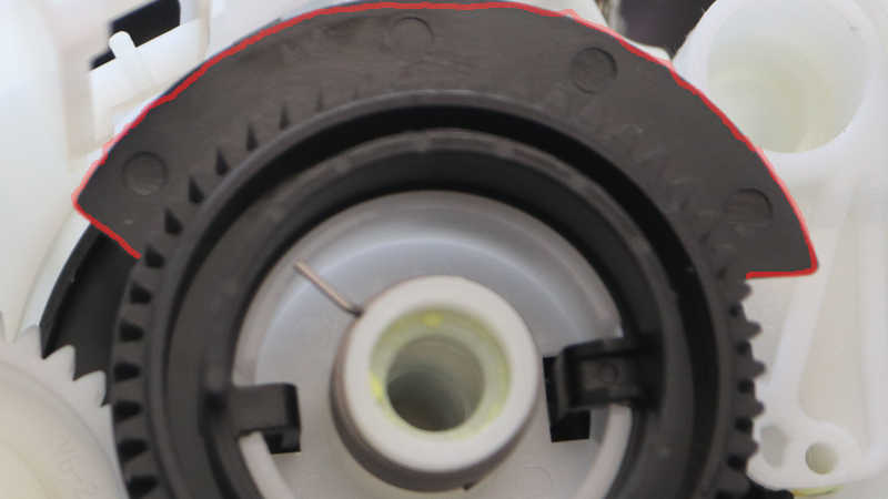
The pin numbers were taken from the system main board, which labeled pin 1 with a number and an arrow (the end closer to camera) and for this cable the other end gets a “22” label (far end, circled in red.)
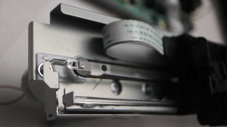
There’s one final sensor I’m trying to access as I tear down my old Canon Pixma MX340 multi-function inkjet: its print carriage linear quadrature encoder. Removing the lower rail allowed the print carriage to slide free, but I first tried to see if I can keep it on the rail. I was afraid sliding it off the rail would unpredictably release the spring-loaded tension mechanisms I can partially see. (White plastic below the belt and behind sheet metal in picture below.)
Without sliding it off the rail, I could access the two fasteners I couldn’t access before. Removing them allowed two separate pieces of black plastic to move apart slightly, but they were both within the lower rail. The carriage has to slide off before I could pull those pieces apart.
As I slid the carriage off the lower rail, my fear came to pass: I heard a “pling” announcing a spring departing to seek new adventures. Its former home highlighted in red on the left, and its companion still in place on the right. Thankfully I managed to find this spring later, because every spring I lose decreases the odds I can repurpose the entire print carriage assembly intact for a future project.
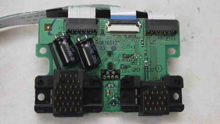
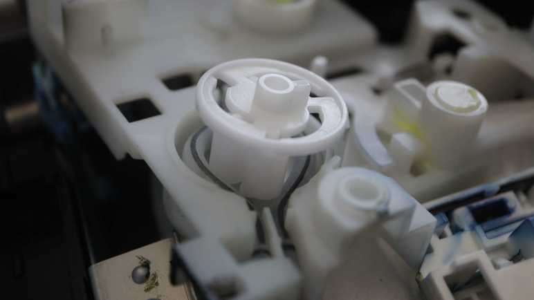
Carefully setting down the rear cover with its many springs, I could see inside the carriage. Front and center is the encoder sensor, but its pins go through the circuit board to the other side. The flexible ribbon cables are also connected on the other side. I will have to remove four more screws before I can see how they are wired.
The flex cable connectors were expected, as are the ink cartridge contacts. The surprise on the front is a pair of electrolytic capacitors. I guess inkjet cartridges need small bursts of buffered power to do their thing.
I wasn’t interested in reverse-engineering the ink cartridge interface, but I was interested in how the electrical contacts are implemented. Each contact is a thin spring-loaded metal blade. (My thumb nail is pushing on one.) Unfortunately, it appears if I want to see more I would have to remove the contact assembly from the circuit board. I haven’t had a great success rate unsoldering components with this many pins, so I will save my unsoldering practice session for later. Right now I’m staying focused on the optical encoder sensor.
I’m close to the end of tearing down my Canon Pixma MX340 multi-function inkjet. After the paper feed motor was freed from the plastic base, there’s not much more I could do to that assembly because I wanted to keep the motor and encoder together. So I turned my attention to the print carriage assembly, with its own encoder I have yet to access.
Earlier disassembly saw fasteners I couldn’t access from the front. I will now take apart the print carriage rail in order to free the carriage itself and allow access to those fasteners.
Looking at the assembly I saw the backbone sheet metal was folded up top to form the upper rail, and there were folds left and right to keep the carriage constrained. The only thing that could move is the lower rail, which is a separate piece of sheet metal. (In above picture, the lower rail is visibly covered with darkened lubrication grease.)
At this point I noticed the lower rail is mounted slightly tilted from the bottom of the backbone. I measured it was raised by 2.07mm on the left but only 1.41mm on the right. This slight tilt was probably part of factory calibration to ensure the print head travels exactly parallel to the paper surface at all times.
Before releasing the lower rail, I unhooked the encoder strip’s tension spring on the left.
The drive belt was also unhooked from the right side tension pulley.
An vertical alignment reference marker is visible to the left of this lower rail screw.
Removing the screw made it clear there’s allowance for a few millimeters of lower rail adjustment.
By removing the lower rail, I have destroyed its precision factory alignment. But with the rest of the printer taken apart I doubt it matters anymore. I’ll ignore that and keep digging.
The process of taking apart my old Canon Pixma MX340 multi-function inkjet has been remarkably easy, something that took deliberate effort by Canon. I recognize their effort and I am grateful. It’s been a fun learning experience and I realized I’m a little sad to be close to the end of mechanical disassembly. But that’s not going to stop me from finishing the job!
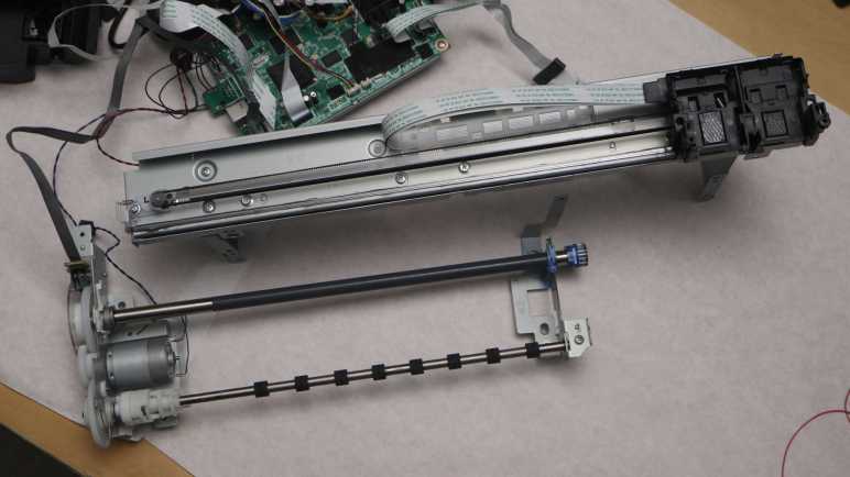
The paper feed motor and adjacent gears (including the rotation quadrature encoder) is the final metal assembly still attached to the base. It also hosts the plastic-and-foam assembly that sits under the paper as it is printed. A typewriter platen is responsible for both feeding paper and holding it against inking impact. Here, the two tasks are handled by two separate parts. The metal shaft with a gray friction coating is responsible for feeding paper, and the rectangular black plastic-and-foam assembly holds the paper directly under the print head. I’m not sure which part technically counts as a platen here, but I’m going to call the rectangular plastic-and-foam assembly the platen.
I see several Philips-head fasteners blocked by the friction-coated feed shaft.
Turning a plastic handle allowed me to lift that shaft up and away, exposing those fasteners.
The fastener left of center is spring-loaded though it’s not clear to me what forces that spring is intended to absorb. The center of this platen is a soft porous foam discolored by a few high-traffic areas of ink absorption. I used this printer for many border-less photo prints. The printer apparently accomplishes this feat by shooting ink beyond the borders to make sure everything is covered, and that ink ends up in this foam. There is a distinct over spray pattern corresponding to 4″ x 6″ photo paper in addition to a less distinct pattern for less frequent full width 8.5″ x 11″ photo paper prints.
Removing the platen and flipping it over, I see several holes where oversaturated ink can drip down to the ink absorbent pads below. It looks like I never needed that provision as the lower pad is still pristine white.
Removing the platen also allowed me access to the remaining fasteners. I had hoped there was only a single piece of stamped sheet metal as they would make it easier to keep the paper feed motor and shaft assembly in one piece. Unfortunately they are two separate pieces. So after lifting them out of the base, things are a little loose and floppy.
Once I made sure none of the rotating pieces are in contact with my table surface, I pressed the power button. The power-up self-test sequence still runs! Things sounded weird because the print carriage was not designed to run facing upwards, and the paper feed motor is no longer driving a bunch of gears. Plus the printer complained that no ink cartridges were installed. But still, it ran! I’m glad it’s still in running condition as I still want to probe the print carriage encoder. I will start that process by disassembling its rail assembly.
Looking at the inner workings of my retired Canon Pixma MX340 multi-function inkjet, I understood many details to be results of making very domain-specific optimizations for mass production. Such details wouldn’t be useful doing anything else, and time and effort required for such work wouldn’t make sense for hobbyist-level projects.
On the other hand, I also found the design reflected a priority for easy serviceability. Something I do aspire to in my own projects. I know serviceability hasn’t always been a design priority in my own projects and it shows. Some people who had build their own Sawppy rover got confused or encounter problems in assembly or repair. By not putting any effort into serviceability, I have implicitly assumed I’ll always have my workbench and that wasn’t always true. Fixing my Sawppy rover in the middle of Maker Faire Bay Area was a huge pain.
With that experience I now recognize effort went into making the MX340 easy to service. Every fastener is a Philips-head screw, the vast majority of which can be turned by a #2 Philips driver. Nothing is glued down, welded, or hydraulic pressed. Everything can be taken apart and reassembled.
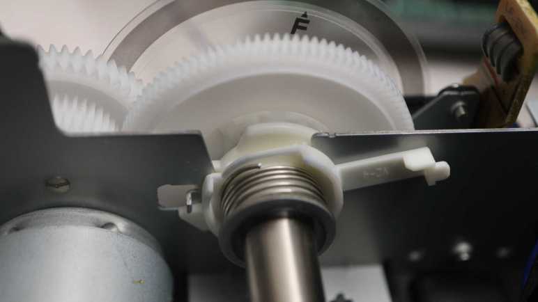
This is the result of deliberate decision by Canon and they had allocated the engineering time to improve serviceability. Some of which is quite elaborate: look at this mechanism securing the shaft that hosted the rotary quadrature encoder. This assembly could have been press fitted into the stamped sheet metal chassis. Simple, reliable, cheap. But that’s not what Canon did.
They designed this plastic bearing carrier so I could turn its arm…
… and lift the entire assembly out of its stamped sheet metal chassis. No tools required.
Why did Canon decide to invest this engineering effort? I assume there must be a monetary payoff. Perhaps this reduces their costs to service devices under warranty? Whatever their reason, my teardown experience indicate it is a very rare thing among consumer electronics manufacturers. It makes teardown projects like this one so much easier and more rewarding. I chose not to reassemble the paper tray sheet feed gearbox to see exactly how it worked, but because it was easy to non-destructively take it apart, I could have done so and that’s is a luxury I don’t take for granted. Up to this point, and as I proceed forward.
I’ve been having fun learning how things worked inside my retired Canon Pixma MX340 multi-function inkjet. Some lessons have direct application to personal projects, especially regarding components that I think I can repurpose in the future. Others are more general, like clever mechanical design concepts that I might be able to adapt to a 3D printed future project. Then there are lessons just for the sake of satisfying curiosity. Looking at implementation details of the paper tray sheet feeding mechanism, I’m definitely in the territory of that last category.
Designing this mechanism took skill beyond what I can comprehend today, orders of magnitude more sophisticated than my 3D printed mechanical contraptions. Part of this stems from the fact I haven’t built up the mental skill to organize knowledge of complex mechanical interactions. My software background gave me ways to think about software interactions, organizing them into API layers and partition module interactions into various levels of abstractions. Looking at a mechanical gearbox where forces can be transmitted via multiple paths to the same destination, at gears that only have teeth to transmit power partway through their circumference, at the freewheel element that turns one way but not another… my brain is overwhelmed trying to keep track of all potential interactions.
I think a good analogy is learning a new language. (The human spoken kind, not the computer programming kind.) It takes some experience to learn enough to mentally catalog and partition the sounds we hear. Knowing where one word ended and another began is an important early skill. Knowing what sounds are critical and what sounds are just person-to-person variation is another big step.
At the moment I lack the equivalent skills to understand and analyze what’s going on inside this gearbox. I also lack the motivation to understand designs optimized for mass-production, which I don’t plan on doing. In other words: if I put in the work to understand it all, I would learn some very domain specific knowledge on a cheaply mass produced mechanism to feed the top sheet of a stack of paper. I don’t foresee that knowledge as something useful to me in the near future. The cost/benefit ratio for diving deeper into this gearbox doesn’t look great, so I’m going to stop here.
Still, I’ve learned a lot of interesting things, and I’m confident this exposure will help me understand more of the next mechanical marvel I encounter in a teardown. A process I intend to repeat until that day when I can look at a complex mechanical system and not get overwhelmed. An iterative process starting with admitting that day is not today, allowing me to focus on other lessons I can more easily absorb.
I’m learning a lot of interesting things as I take apart my retired Canon Pixma MX340 multi-function inkjet, like how they implemented freewheel capability with just a single coil of metal between two gears. Another ongoing lesson: my design priorities for a hobbyist project differs from Canon for their mass produced commercial project.
Here’s the latest example: once I’ve removed all gears and cams from the paper tray gearbox, I’m left looking at this trio of levers. (Highlighted in pink) Each actuate some aspect of the paper tray during its page-feeding process. If I were to implement such a mechanism in a 3D-printed hobbyist project, I would install a micro servo for each of these functions and write microcontroller code to fine-tune coordinating servo motion timing. Come to think of it, Canon engineers probably have exactly that rig on their workbench. They would need something dynamically adjustable so they can fine tune timing in their sequence, test performance of one design against another. Once a sequence is declared to be the best tradeoff across all design criteria, though, what happens?
For a hobbyist project, I would stop there. I push my microcontroller source code (Arduino sketch or similar) to GitHub, along with 3D printing CAD/STL and maybe a KiCad schematic, then I move on to my next project.
For Canon engineers, there’s a lot of work still ahead. They will need to convert their software-defined paper feed sequence to mechanical hardware. Translating servo-actuated motion into lever-actuated motion, design cams to move those levers, and a gearbox to turn those cams to the right position at the right time. This takes work but it is an one-time up-front investment. Once the design is converted into injection-molded plastic, it can be cranked out at a tiny fraction of the cost of manufacturing something with multiple servo motors.
For a MX340, this trio of levers marked the end point in my effort to trace through all activity powered by the paper feed (Y-axis) motor. Backtracking from here, there was the big paper tray rubber-coated roller, ink disposal peristaltic pump, print carriage parking pawl, front door panel opening mechanism, and probably others I didn’t even notice. If I were to do it my easy way, that’s at least eight different motors. Canon engineers put in the time to optimize down to a single motor.
This results in a lower per-unit parts cost and higher long-term reliability (cams > servos) which more than makes up for the higher up-front design effort when amortized across thousands (millions?) of production units. But it wouldn’t make sense for my own projects with a production volume of one.
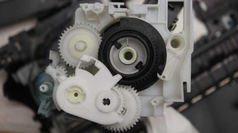
The paper sheet feeding mechanism in my retired Canon Pixma MX340 multi-function inkjet is a mechanical marvel. There are details I didn’t understand until a second or third look, like the spring that was installed on top of the big black gear driving the output cam. When I first saw it I thought it wasn’t a big deal. It looks like a spring, probably there to absorb some kind of shock to the system. No big deal, except I was wrong. The real story was actually much more interesting: it’s a freewheel mechanism.
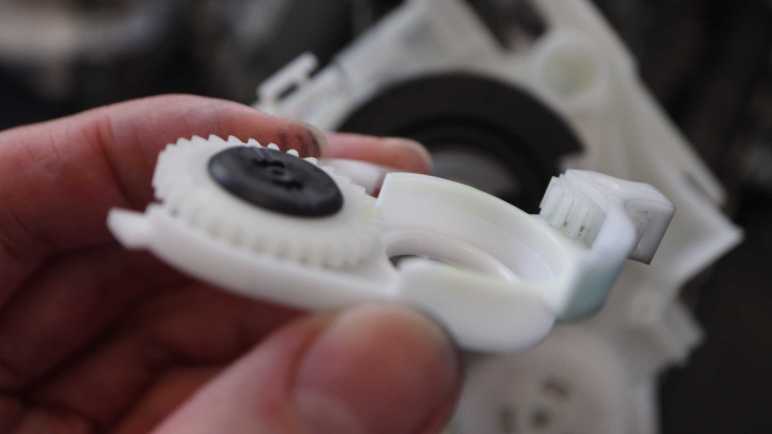
My lesson came from a different part of the gearbox. This pair of gears were mounted on a static shaft that did not turn, so this pair exists to convey rotational power from one gear to the other. But if they were a straightforward direct coupling, they could have been injection molded as a single piece. Their multi-piece assembly hinted at something more, so I picked it up and started playing with it. I quickly found that I could rotate the top gear (as viewed in picture above) counterclockwise while holding the bottom gear static, but if I try turning the top gear clockwise they would lock up and turn together.
Aha! It’s a way to ensure something only turns in one direction. A concept implemented several different ways (example) all inside this gearbox. I also knew this concept from the rear wheel of my bicycle, allowing me to coast without having to pedal in sync. I knew there had to be a term for this common concept but my search efforts came up empty. I ended up asking my friend Emily Velasco (who has bike hacking among her many talents) for help and she told me it’s called a freewheel. Unlike the rear wheel hub of my bicycle, this pair of gears didn’t make the clicky-clack noises of a ratchet mechanism. It was smooth and quiet so I had to see how they implemented it. Maybe it’s like one of the illustrations on Wikipedia, a series of spring-loaded ball bearings all around the perimeter? Maybe a clever arrangement of many layers of friction material?
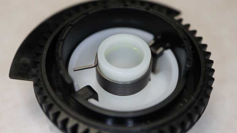
I popped the two gears apart and between them I found only a single metal coil. Wow. How did this work?
I first focused on this detail: both ends of this coil stuck out beyond the coil diameter. I believed it would allow them to smoothly coast along a surface in one direction, but dig in when moved in the opposite direction. A little bit of this dug-in force would expand the diameter for this coil, relaxing its grip on the inner cylinder (half from one gear and half from another) and allowing gears to turn independent of each other. As soon as the direction reverses, the coil contracts back down to its normal diameter and its grip keeps the two gears moving in sync. Torque transmission would have been limited by the friction of the metal coil against slick white plastic, but it’s more than enough to resist my finger strength and evidently enough for this application.
On further examination, I changed my mind. I looked inside the coil housing for any marks of surface damage from coil ends digging in, and found it completely smooth to my eyes. Also, for long-term durability, it would make sense to avoid any mechanism that destroys the surface over time. Perhaps friction against the coil interior, without any wedge dig-in action, is enough for this design to work. [UPDATE: Indeed it is! Emily Velasco told me this is an example of capstan effect.] If so, the fact that the coil ends stuck out beyond its diameter may merely be an artifact of its manufacturing process.
One data point supporting the “friction is enough” hypothesis is the fact this coil is wound from thin metal wire with a square cross section instead of the typical round wire. This would help maximize contact surface area.
Another supporting data point can be found on the big black output gear, where one end (the <1cm length of metal stub) is held static at all times and the other end has nothing to dig into. This is enough to allow counter-clockwise (as viewed in this picture) rotation but resist clockwise rotation.
I found a slot for that metal stub on the gearbox lid that holds the stub in place.
Getting this functionality from a single precision-manufactured coil of metal is a feat of mechanical engineering and manufacturing that impressed and amazed me, and I almost missed it entirely. Given that, I’m sure there are many other details in this gearbox that has gone completely over my head without me noticing, because they are designed to priorities different from mine.
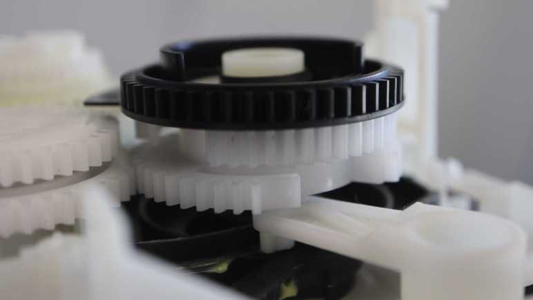
The paper tray in my retired Canon Pixma MX340 multi-function inkjet has a box of mechanisms to orchestrate its page-feeding sequence. Powered by the paper-feed motor, two different actions can be triggered from a gear shifting mechanism by engaging one of two gears. But there was at least one more gear interaction: The forward gear position can be inhibited by another gear, part of the largest assembly in this box.
I didn’t notice this interaction at first, but as I looked at the lever in detail, I noticed a protrusion up top. Given all the design optimizations I’ve seen so far, I knew that protrusion could not have been accidental. I saw it could push against a wall on the big black gear that covered only roughly 240 degrees out of the circumference. This would inhibit engaging the forward gear.
When within that ~120 degree gap, though, it is possible to engage forward gear. I thought it was neat, but as soon as I looked at this big black gear more closely, I realized that was just the beginning. If the black gear continued turning counter-clockwise in this picture, the wall will eventually push on that protrusion and pop it out of gear.
Beyond the ring of gear teeth, I see a thin piece of plastic covering a different ~120 degree arc. This slotted into a photo-interrupter sensor. Looking at the two mechanisms, it appears the beam is interrupted when we’re within the arc where forward gear engagement is allowed.
Which led me to the next question: why would the angle matter in a spinning gear? The answer can be found in layers attached below this big black gear. I saw two white plastic gears, but they didn’t have teeth all the way around. Both are missing teeth (roughly 45-60 degrees worth) at different positions. Adjacent to one side of this gap, 5 gear teeth are mounted on an unsupported arch while remaining gear teeth are mounted rigidly.
I interpret this as a mechanism that can convey motion for part of a rotation before falling into a gap. To re-engage the gears, it would have to turn in the direction of those arch-mounted teeth. Taking advantage of their slight bit of flexibility to help gears mesh back up instead of grinding like a student driver learning a manual transmission car. I never noticed any gear-grinding noises from this machine so I guess it works and reliable enough for years of service.
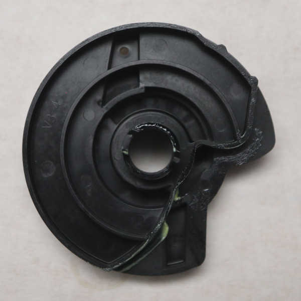
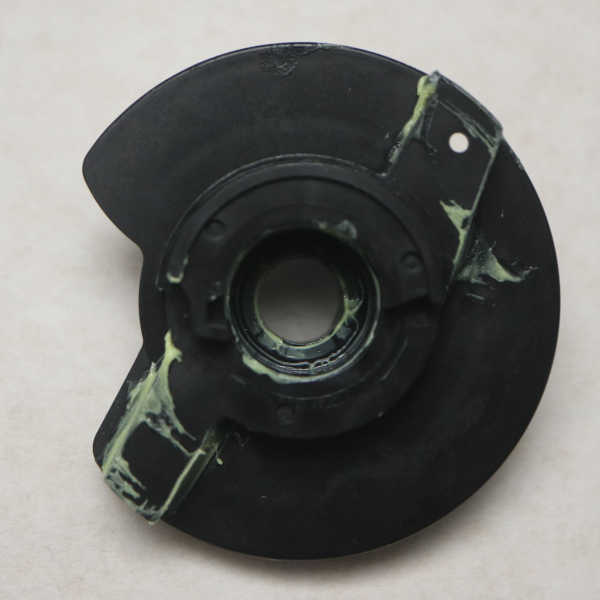
Attached below the pair of intentionally incomplete gears is another piece of black plastic. A cam mechanism with contours to move arms that actuate mechanisms in the paper tray. The “top” side visible in above picture controls the large spring-loaded flap of the paper tray (labeled “1” below) and the “bottom” side of this cam has two separate contours for manipulating two other mechanisms (“2” and “3”).
Here are some pictures of the cam by itself.
And a picture of the paper tray. with numbers labeling its moving mechanisms.
All this added up to a lot of mechanical sophistication attached below that big black gear. What I had thought was just another gear in the gear train turned out to be the output shaft for coordinating many separate actions related to feeding a sheet from the paper tray. It even incorporated a freewheel mechanism, something I overlooked at first.
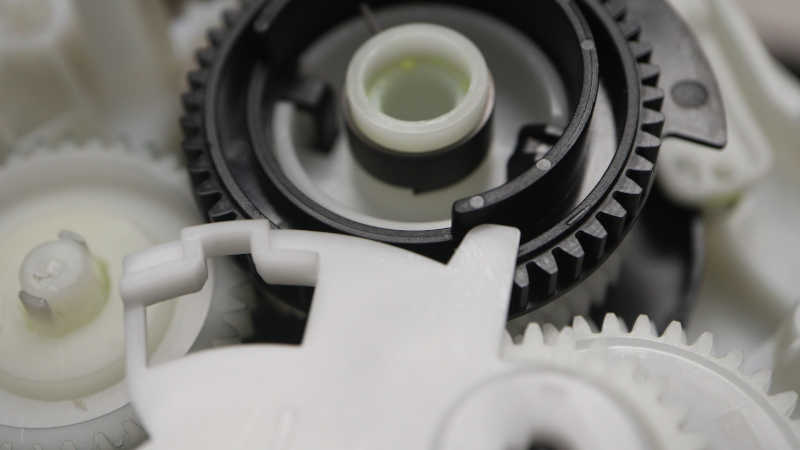
I’m getting into some very interesting mechanisms inside my retired Canon Pixma MX340 multi-function inkjet. After taking a look at its ink disposal peristaltic pump, my next focus is on a gear shift mechanism I identified earlier as the starting point to feed a single sheet of paper. With the cover removed, I can see it is a lever riding on one gear axle and with two other gears on either arm of the lever. This center gear always turns when the paper feed motor turns, driving the ink disposal pump.
When “Forward” gear is engaged (circled in red) it conveys motion to the large black gear.
When “Reverse” is engaged, power from the same driveshaft (but a different gear riding on the same shaft) is transmitted to a gear driving the paper tray large roller.
Under and to the left of that mechanism is the print carriage parking pawl, sitting on the same axis as the gear conveying power from the paper feed motor. Earlier I was curious if this pawl also played some gear-shifting role. Now I have my answer: It does not.
It wasn’t just sitting loosely on that gear, though. A length of spring steel maintained a level of tension/friction so the pawl will always move in response to a change in direction. I found a similar mechanism in its lid closing damper.
Anyway, back to the shifter. Removing it from the assembly showed that forward and reverse gears are offset from each other in order to engage adjacent gears riding on the same shaft.
I thought understanding this lever would tell me how this gearbox worked, but I underestimated the amount of mechanical wizardry I would find within. This was just the tip of the iceberg. The more I look, the more I find.
Tracing through path taken by the ink disposal system in my Canon Pixma MX340 multi-function inkjet, I noticed a circular assembly that hinted at a peristaltic pump. My guess was quickly confirmed after I opened up that assembly. I lifted up the rotor and, yep, it moves a trio of rollers across those tubes.
This thing has some interesting differences from the basic textbook design for a peristaltic pump. The most obvious difference is that, instead of a single tube, this pump is working to move fluid through two tubes on opposite sides. There are three rollers spaced 120 degrees apart, so at any given point at least one roller is in contact with each tube. But it’s rare for the third roller to have contact at the same time. There’s barely time for any two rollers to work together before one of them departs for the other tube.
What might be the tradeoffs of jamming two tubes into one pump like this? I don’t know how important it is to have multiple rollers in simultaneous contact. Always having one in contact should be enough to ensure things move along and nothing sneaks back. I guess perhaps this design would be less capable of moving thick (viscous) fluids or pushing against back pressure. But this pump is working with watery (low viscosity) ink and dumping them off into an disposal area that exerts no back pressure. So even if those tradeoffs were real, they would not cause any issues in this application.
A standard peristaltic pump works in both directions, but here we don’t want to pump ink or even air back into the maintenance tray. This pump rotor is designed so it only pumps in one direction. The trio of rollers each sit in their own spiral track. When the rotor is rotating in the pumping direction (counter-clockwise in picture above) the rollers are pushed outwards so they press on the tubes and do their thing.
When the rotor turns the other way (clockwise in picture) the spirals retract all three rollers inwards. It looks like they still make contact with the tubes, but not exerting enough pressure to pinch off tube interior and thus no pumping takes place.
I thought this is a very clever way to modify the standard peristaltic pump design so it only pumps one way. Much simpler and less prone to failure than introducing, say, a gear engagement/disengagement mechanism. This peristaltic pump rotor is always coupled to the paper feed motor. When that motor feeds paper forward during printing, these rollers retract. When the motor spins backwards relative to printing direction, the rollers extend for pumping action. This pump is a good explanation for long backwards motions performed by the printer during its various startup/prep/shutdown procedures.