RX-8 Backup Camera Bracket

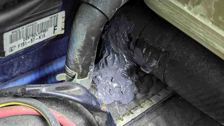
I’ve decided to retrofit a backup camera to my 2004 Mazda RX-8. After running the camera wire from the dashboard receiver into the trunk, I had to install the camera somewhere and plug into that wire. I decided to put the camera near my rear license plate, which meant I had to remove many old brittle plastic fasteners before I could remove my rear bumper cover. I was happy to find I didn’t need to drill any holes in either the body or the bumper cover. There’s a slot already in the bumper cover to accommodate a license plate light, and it’s much wider than it had to be. The metal body had several existing holes I could repurpose for my project. I removed an existing plastic-and-rubber plug to run my camera wire, followed by a dab of hot glue to plug it up so rain water does not enter.

That leaves the problem of exactly where to mount the camera. The bundle came with a license plate bracket that would mount it centered above the license plate, but that would block my license plate light and I doubt law enforcement would be happy about that. It also came with a small bracket and double-sided foam tape but I didn’t trust tape under SoCal summer sun. I had a metal frame around my license plate purely for aesthetics, so I drilled and tapped two M3 holes in the frame corner for the small bracket.

I was so focused on the camera that I didn’t notice what I had done until I took a step back and looked at the situation: the camera now obscures my license plate registration sticker, and that’s going to make local law enforcement even grumpier than if I had blocked the light.

I have a stack of small thin aluminum sheets waiting for a project, and I decided to fashion a mounting bracket from one of them. I don’t have real sheet metal cutters (it’s on my tool shopping list) but this aluminum is barely thicker than kitchen foil and easily cut with diagonal cutters.

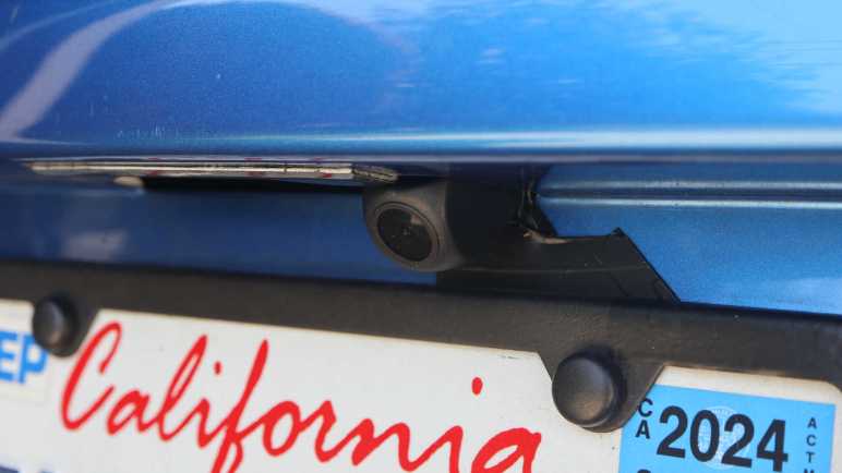
A test fit looks good, tucking the camera into the existing slot adjacent to the license plate light so I don’t block the light.

Now the camera draws less attention and it doesn’t block my registration sticker either. Looks great, I’ll keep an eye to see how well it holds up long term. Onward to the next project.

RX-8 Navigation Upgrade Project Phase Two: Backup Camera

My 2004 Mazda RX-8 has a cracked radiator. While I wait for a replacement radiator to be shipped to me, I’ve applied some J-B Weld as a short term workaround. And since I already have tools scattered about my garage, I thought I would work on a few more RX-8 project to-do items. First on the list is I will resume my navigation screen upgrade project. I had removed the stock GPS navigation system LCD screen and replaced it with a standalone receiver for wireless Android Auto/CarPlay. My receiver came bundled with a backup camera, but I decided against tearing up too much of the car before I decided if I even like the receiver. So I paused after receiver installation to evaluate.

It’s been a few months and the inexpensive receiver has not been perfect. I have to manually adjust screen brightness between daylight and night time driving, but that’s only 3 taps and a mild annoyance I can live with. I’ve had the occasional audio stutter and data dropout, reminding me why wired connections are always more reliable than wireless. Sadly wired Android Auto/CarPlay have fallen out of favor with standalone receivers like these. I’ve also seen the thing crash and reboot itself, but not often enough for me to recognize any pattern to what might have trigger it.

Despite its imperfections, I have grown fond of having my phone automatically connect to my car every time I start it up. It’s nice to always have Google Maps on screen and access to my entire audio entertainment library stored on my phone. Given its low price ($60 as of this writing *) I can forgive a few hiccups here and there. It’s a keeper! I will now proceed to install that backup camera which had merely been gathering dust the past few months.

Accessing the stock factory navigation display hood is a lot easier the second time around. I now know enough to avoid completely disassembling the center console like I did the first time. For example, now that I know I only need to access two fasteners behind the factory audio head unit’s face plate, I only need to slide it out a few centimeters leaving all wire bundles connected. Much easier this way!

After plugging the camera cable into the receiver, I ran its wire down the left side of the center console. Under the ashtray and along the center of the car underneath all cupholders. I mostly followed the existing navigation computer wiring harness. Speaking of which, I took this opportunity to unplug all connectors from that outdated computer so it doesn’t consume power uselessly. I thought about removing it entirely but I didn’t want to leave a hole in the console between rear seats. The backup camera cable proceeded under the now-unplugged computer, behind the right rear passenger seat back, and into the trunk where it can meet up with the camera module. That takes care of the electrical wiring, now I need a camera mounting bracket.


(*) Disclosure: As an Amazon Associate I earn from qualifying purchases.

Temporary Radiator Fix Using JB Weld

I noticed a coolant leak on my 2004 Mazda RX-8 and tracked it down to a cracked radiator housing. The good news is I think I caught this problem before it caused any serious problems, the bad news is that it’s hard to get parts for a low volume car that’s over 20 years old. I had no luck finding a (reasonably priced) replacement radiator locally, so I ordering one to be shipped to me.

What do I do in the meantime? I suppose I could continue driving the car, frequently topping off the coolant reservoir with water. I don’t think that’s a good way to go, though, because hot pressurized liquids have a history of making small cracks bigger. Possibly turning this radiator failure into an overheated engine failure. So I decided to try plugging the leak with some J-B Weld. I learned of this miraculous product from watching 24 Hours of LeMons video summaries, helping many teams get their car back out on the track.

This will be my first opportunity to use the product myself, and a great practice opportunity! Since I plan to replace the radiator soon, it won’t really matter how well the product works. But I will gain the experience of using it, and a short period of seeing it in action. For some guidance I enlisted my friend Emily Velasco who has J-B Weld experience and here’s what we did:

For surface prep, the surface around the crack was cleaned up and sanded down to give the epoxy a rougher surface to grip on to. The coolant level was drained below the height of the crack so it would quit weeping out which would interfere with epoxy adhesion. Once the area was clean, roughed, and dry, the first batch of J-B weld was mixed and applied.

For patch jobs like this, Emily recommends putting in something to help add structure to the blob of epoxy. A thin sheet of metal is common, and I remember seeing LeMons racers cutting up old license plates for this role. Unfortunately, we are dealing with a compound curve here so bending a sheet of metal to shape is difficult. As a workaround, our Home Depot run involved picking up a sheet of fiberglass cloth (Bondo 20128) along with J-B Weld. Emily recommended using the original formula and not the quick-cure type I saw in LeMons videos, because unlike them I am not in any pressure to get back out on the track.

A small square of fiberglass cloth was cut out and pushed into the still-soft first layer of J-B Weld. After the first layer had set (4-6 hours) but before it cured (15-24 hours) a second batch was mixed and applied on top. The result is not pretty, but it held well enough to stop further coolant leaks. The awkward position of the crack meant we got some J-B weld on adjacent components though I don’t think they’ll get in the way of future radiator replacement. I hope this old radiator’s brittle plastic doesn’t crack somewhere else while replacement radiator is still in shipping.

While I wait on arrival of that radiator, I decided to tackle other RX-8 projects on the to-do list starting with installing a backup camera.

Tracing Mazda RX-8 Coolant Leak to Cracked Radiator

I bought a pack of commodity 8mm plastic fasteners so I could replace old and brittle fasteners on my 2004 Mazda RX-8. I knew there were a lot of them holding the front bumper cover in place, fastened to wheel well liners and other adjacent pieces. And I knew I would have to deal with them because I noticed a puddle of coolant under the car when it is parked. There is a leak I have to track down!

The radiator is tilted forward roughly 45 degrees so the top edge is ahead of the bottom edge. Immediately above one side of the radiator is a coolant reservoir tank. From this pair, several hoses large and small lead backwards to the engine and cabin heater core. Given this knowledge, I was mystified by my observation coolant is dripping from somewhere in front of the radiator. I don’t understand how coolant got so far up front, but to get a closer look I need to remove the front bumper cover and several airflow management panels directing air through the radiator. About a dozen of those 8mm plastic fasteners later, I can get a clear look at the air conditioning condenser and the radiator immediately behind it.

Given the car’s age, I had expected to find coolant leaking from an old cracked radiator hose. It’s a common failure point and inexpensive to fix. But the forward drip location made me suspicious that might not be the case. Tracing dripping coolant back to the source, I found the leak and it was indeed not a failed hose.

The top of the radiator has cracked between two hose fittings, near the base of a hose fitting leading to the engine. The failure point is very inconveniently positioned for picture-taking. This is the best I can do, which required removing the battery and engine air filter box, and even then I know this picture lacks context.

Here’s an annotated version which might help. The camera is in the engine compartment looking roughly forward-right, but tilted at an angle. I have two arrows labeled UP and FRONT to designate those orientations. The crack is still very small and when the engine is cold, barely any coolant dribbles out flowing down the front of the radiator. However, when the engine is hot and cooling system is pressurized, a very thin stream of coolant shoots out of the crack towards the front. This stream will strike a piece of chassis metal ~10cm away before falling and that is why I saw coolant dripping in front of the radiator.

I’m glad I caught this problem before erosion expanded the crack big enough to drain all coolant and cause an engine overheat. I believe this is the original 20+ year old radiator. While the radiator core is made of aluminum cooling channels and fins, the top and bottom caps are made of plastic. Searching through RX-8 owner forums, old radiators cracking their brittle plastic is a known failure. Radiator replacement is the correct fix. Patching the crack will only be a short term fix because that old brittle plastic will fail somewhere else soon enough.

Commodity Plastic Fasteners (8mm Diameter)

I have several projects on the to-do list for my 2004 Mazda RX-8, but I had been procrastinating because I hated dealing with its plastic fasteners. These are designed to fit in holes roughly 8mm in diameter and hold two or more pieces together. Usually at least one of those pieces is a flexible body trim panel.

They are made from two pieces: an center portion that pushes against the outer portion so the latter expands to hold the fastener in place.

Here’s what the head looks like in the fastened state.

In theory, we release this fastener by a quarter-turn of a Philips-head screwdriver.

This pushes a few wedges/ramps against each other and pops the center free, allowing the outer portion to contract and letting us pull the fastener out of its hole.

In practice, years of road dirt and grime jams up the works so the center doesn’t want to turn. Applying more torque risks stripping the slot, and the typical technique to avoid cam-out is to push my screwdriver harder inward. This force directly defeats the purpose of the turn, which is to pop the center outward! I’ve always felt it was a bad design to put such forces in direct opposition to each other. Despite my efforts to avoid damage I would end up stripping the inner slot and have to find some other way to release the fastener. This usually ends up damaging the fastener (this one’s outer ring is cracked) as well as the panels it had fastened to.

I’m not sure if these are factory original Mazda parts, but I do know I have came across multiple different fasteners on my car. Some of them might have been fitted by mechanics who have worked on my car over the past two decades. I understand why they would perform such substitution, and I will follow their lead.

My criteria was to find something advertised for 8mm holes and suited for outdoor environment applications. These are pretty generic commodity parts used across multiple industries for different purposes, but there doesn’t seem to be a commonly agreed upon name for these things. I settled on an Amazon product that just incorporated a bunch of different words into its lengthy title: 200PCS 8mm UTV ATV Fender Push Clips with Fastener Removal Tool, Nylon Body Rivets Fasteners Clips Compatible with Polaris Ranger RZR Can Am Kawasaki Teryx Honda Suzuki Sportsman (*)

And the best part: this design doesn’t require self-defeating forces to remove. Again this center component is designed to pop out, but this time it’s not the turn of a Philips screwdriver. Instead, this has side slots for me to pry against to pop them out.

On the downside, these lowest-bidder items are definitely not as nicely made, with crude plastic injection molding flash all over. Diameter of the head is not as large as my original fasteners, and length is slightly longer. Despite these differences they seem sufficient due to the loose tolerance nature of the application. They are good enough for today but the real test will come years down the line when I try to release one seized up from years of dirt and grime. I figured even if it doesn’t release, I could take a large pair of diagonal cutters and cut it off. I know how to get plenty of replacements.

Having that option is great, because it greatly eased projects that require dealing with such plastic fasteners. And I already have one on my hands: tracking down a coolant leak.


(*) Disclosure: As an Amazon Associate I earn from qualifying purchases

Proxmox Cluster Node Removal

I’ve transferred the core of a computer into a 3D-printed case, reducing the volume it took up on my shelf. It’s been part of my Proxmox experimentation, getting a feel for the software by playing with different capabilities. One notable experiment was putting two machines together into a cluster, and seeing how easy and seamless it was to migrate virtual machines between them. It was really neat!

Thankfully, the Realtek network problems which forced my hand with VM migration has been resolved, and my Dell 7577 has run reliably for several months. Since it draws less power than a Mini-ITX desktop, I decided to migrated all my virtual machines back to the 7577. This will free my Mini-ITX system to be powered down for now and available for other experiments in the future. I found instructions for removing a Proxmox cluster node, but the command failed with the error message: “cluster not ready - no quorum? (500)

Major cluster operations requires quorum, defined as a majority of nodes ((number of nodes/2)+1) to be online and actively participating in cluster operations. Adding and removing cluster nodes qualify but apparently there are built-in exceptions for adding the first few nodes because by definition we have to start with a single node and build our way up. But there is no built-in exception for removal and thus I’m prevented from dropping node count back down to one.

Searching Proxmox forums, I found a workaround in thread Another “cluster not ready – no quorum? (500)” case. We can suppress quorum requirements with the command “pvecm expected 1“, then proceed with the operation that typically require quorum like removing a cluster node. Since quorum requirement exists to make sure we don’t fatally damage a Proxmox cluster, this is a very powerful hammer that needs to be wielded carefully. We have to know what we are doing, which may include requirements outside of the actual act of removing a node.

In my case, I am responsible for making sure that the removed node never gets on the network again in its current state. I unplugged the network cable from the back of the motherboard and used a Windows 10 installation USB drive to overwrite Proxmox with Windows 10. That should do it.

MODCASE MASS (Free Edition) 3D Printed Mini-ITX Case

A nifty-looking 3D-printed computer case came across my attention recently: Modular Attached Storage Stack (MASS) by MODCASE. Just like the name says, it is a modular stackable system for building data storage servers, featuring a core module for the motherboard and PSU and however many hard drive modules you want. There is a paid version with additional features but I wanted to try the free version first as it should be sufficient for my immediate needs. I downloaded the 3D printer STL data files from Printables.com, and dusted off my 3D printer for a go.

My objective is to give the guts of my decommissioned Luggable PC Mark II a decent home. The Mini-ITX motherboard and compact SFF power supply had been taking up a full-sized tower case and that is silly. Especially since it doesn’t have any storage drives: at the moment it is a Proxmox server and all I need is the M.2 NVMe SSD on the motherboard. So why am I printing a storage server case? Because (1) I think this will become a storage server in the future and, (2) for today I can print just MASS core without the storage modules.

Printing MASS modules proved to be challenging due to many sharp right-angle corners that want to lift as PETG cooled. I know my print bed adhesion is not perfectly dialed in and MASS rubbed it in my face with multiple failed prints.

Once printed and assembled, though, MASS core was impressively compact. Here is a size comparison against a Cooler Master Mini-ITX case. For my current purpose I did not need the externally accessible 5.25″ drive capability or three internal 3.5″ drive bays, nor do I need to accommodate a full-sized ATX power supply. Trading off those capabilities meant MASS has roughly 1/3 of the volume. And this is with a fairly thick and robust design, as it may potentially be asked to support the weight of multiple drive modules. I think 1/4 volume is achievable if the case doesn’t need to be as robust.

Since MASS is a 3D-printed case, we are on our own to supply all components that typically come with a commercial computer case. Mounting screws and nuts, external USB ports, etc. A critical component is a normally-open momentary-close power switch. I enlarged the provisioned buttonhole to fit an illuminated button I salvaged from a dead Form Labs Form 1+.

The power supply side of my build is pretty packed with power cables. There would be less crowding if a power supply with modular cable system is used instead.

The mainboard side, however, is unobstructed which is great for cooling. It would also ease routing SATA cables necessary to turn this into a storage server. This particular motherboard has six SATA ports, but Mini-ITX boards typically have fewer.

For more storage capability, there might be enough room for a low-profile HBA (Host-Based Adapter) card from a vendor like Art of Server. But without a way to screw the metal back plate down, it would not be held securely. This is one reason to step up to the premium version of MASS as it has explicit provision for installing a low-profile PCIe card.

MASS side panels are held in place with stumps that clip into the case. These stumps are liable to break off if layer adhesion is less than perfect. Apparently mine are not!

I have put my MASS core into service and it has worked well so far. If somebody has a 3D printer that can avoid my issues with corner lifting or layer adhesion, MASS is a great choice. If their printer isn’t perfectly dialed in, I would warn to expect some level of print frustration. I probably won’t print MASS again but that’s no fault of the design. I’m just more likely to take a stab at designing my own case reflecting my own priorities.

Test Run of Quest 2 and Eyeglasses

OK so sticking some googly eyes on my Quest 2 wasn’t a serious solution to any problem, but there was another aspect of Apple Vision Pro I found interesting: they didn’t make any allowances for eyeglasses. Users need to have perfect vision, or wear contacts, or order lens inserts that clip onto their headset. This particular design decision allows a much slimmer headset and a very Apple thing to do.

Quest 3 headset has similar provisions for clip-on lenses, but my Quest 2 did not. And even though Quest 2 technically allowed for eyeglasses, it is a tiny bit too narrow for my head and would pinch my glasses’ metal arms against my head. I thought having corrective lenses inside the headset would eliminate that side pressure and was worth investigating.

Since Zenni isn’t standing by to make clip-on lenses for my Quest 2, I thought I would try to get creative and reuse one of my retired eyeglasses. I have several that were retired due to damaged arms and they would be perfect for this experiment. I selected a set, pulled out my small screwdriver set, and unfastened the arms leaving just the front frame.

For this first test, my aim is for quick-and-dirty. I used tape to hold the sides in place. For this first test I didn’t bother trying to find an ideal location.

The center was held with two rolled-up wads of double-sided foam tape. I believe the ideal spacing is something greater than zero, but this was easy for a quick test.

Clipping the face interface back on held my side strips of tape in place. I put this on my face and… it’s marginally usable! My eyesight is bad enough that I would just see a blur without my eyeglasses. With this taped-on solution, made without any consideration for properly aligned position, I could make out majority of features. I still couldn’t read small text, but I could definitely see well enough to navigate virtual environments. I declare this first proof-of-concept test a success, I will need to follow it up with a more precise positioning system to see if I can indeed make my own corrective lenses accessory for my Quest 2.

Reducing VR Headset Isolation

One advantage of Quest 2’s standalone operation capability is easy portability. I have a friend who was curious about VR but wanted to get some first-hand experience, and we were able to meet up for a demo with my Quest 2. No need to lug around a powerful PC plus two lighthouse beacons for a Valve Index.

At one point during the test drive, my friend turned towards me to talk about something. He can see where I sat as he had pass-through camera view active, but all I saw in return was the blank white plastic front surface of my Quest 2. It was a little disconcerting, like conversing through an one-way mirror. After that experience I understood the problem Apple wanted to solve with Vision Pro’s EyeSight feature.

It’s a really cool idea! EyeSight is a screen mounted on front of the headset and displays a rendering of the wearer’s eyes so people around them has something to focus on. There’s a lot of technical sophistication behind that eye rendering: because Vision Pro tracks direction of wearer’s gaze, those replicated eyes reflect the actual direction wearer is looking at. Our brains are high evolved to interpret gaze direction (very useful skill out in the wilderness to know if a saber-toothed cat is looking at us) and EyeSight aimed to make it effortlessly natural for all our normal instincts and social conventions to stay intact.

I have not seen this myself but online reports indicate EyeSight falls short of its intention. The screen is too dark to be visible in many environments, a problem made worse by the glossy clear outer layer reflecting ambient light. It was further dimmed by a lenticular lens layer that tries to give it a 3D effect, which is reportedly not very convincing as those rendered eyes are still obviously in the wrong place and not the real eyes.

Given Apple’s history of hardware iteration, I expect future iterations of EyeSight to become more convincing and natural for people to interact with. In the meantime, I can build something with 80% of the functionality for 1% of the cost.

I stuck a pair of self-adhesive googly eyes(*) to the front of my headset, and that will give human eyes something to look at instead of a blank white plastic face. It bears no resemblance to the wearer’s eyes within (or at least I hope not) and does not reflect actual gaze direction. On the upside, it is a lot more visible in bright environments and a far more amusing. Yeah it’s a silly thing but don’t worry, I have serious headset modification project ideas too.


(*) Disclosure: As an Amazon Associate I earn from qualifying purchases

Quest 2 Standalone and Mixed Reality Operation

While it was instructive to compare Quest 2 specifications with my other VR headsets, the biggest reason I wanted to try a Quest 2 is its standalone capability. After spending some time I’ve decided I’m a fan. It’s much easier to enjoy a virtual environment when I’m not constantly kicking away the cable tethering me to my gaming PC. All else being equal, a wireless experience is superior. Unfortunately, all else are not equal. The cell phone level hardware in a Quest 2 renders a decidedly lower fidelity world relative to what a modern gaming PC can render. It’s a nonissue for something simple and abstract like Beat Saber, but anything even slightly ambitious looks like a PC game from at least ten years ago.

One way to have the best of both worlds is wireless streaming from a gaming PC to my Quest over home WiFi. I tried Steam Link on Quest and was impressed by how well it worked. Unfortunately, it doesn’t work quite well enough just yet. When I’m playing games on a monitor, a few milliseconds of latency plus an occasional (about once per minute) stutter of one or two frames is fine. But on a VR headset, it quickly gives me motion sickness and a headache. Supposedly this can be improved with a WiFi 6 router, but I’m not willing to replace my home WiFi infrastructure for this feature. For the immediate future, I’m happy using my Valve Index for SteamVR experiences.

Mixed Reality

And finally, Meta’s push for Mixed Reality is still a question mark. All three of my VR headsets let me use their cameras to see real-world surroundings. But Quest is the only one of the three to do the work to map that camera footage into a convincingly realistic spatial layout around me. The HP WMR and Valve Index camera views can give me a rough idea if I’m about to run into a wall, but neither are properly mapped enough for me to, say, reach out and grab something.

To support mixed reality scenarios, Quest advertises hand-tracking capabilities for controller-free experiences. Supposedly this works well on the Quest 3, which has additional color cameras for the purpose. My house has beige walls and carpet so my hand has poor contrast for Quest 2’s black-and-white cameras to pick out. It’s pretty unreliable today.

Both of these capabilities show promise, but they’re both relatively new and I will have to wait for novel usage to emerge in mixed reality experiences yet to come. Apple’s Vision Pro is all-in on mixed reality, though, and offers to solve a problem that the Quest 2 does not.