KMK Firmware Revives Acer Aspire Switch 10 Keyboard Module

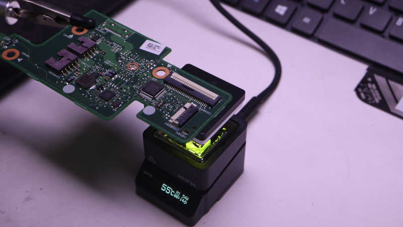
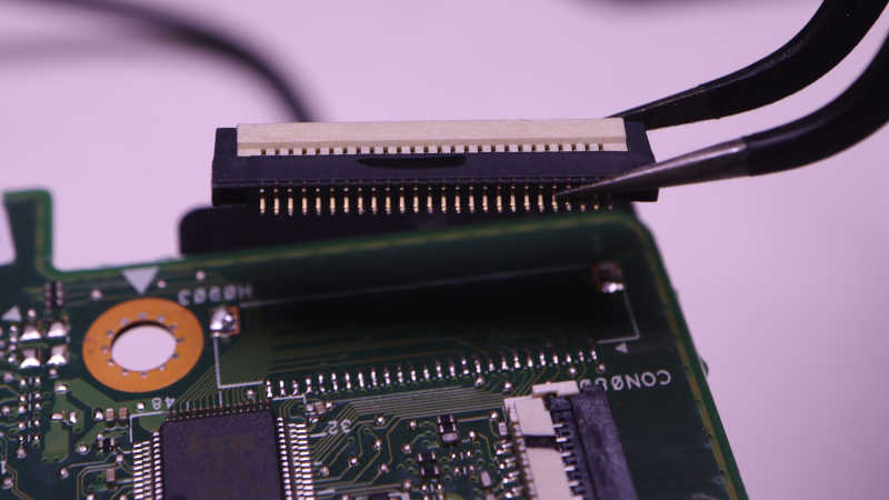
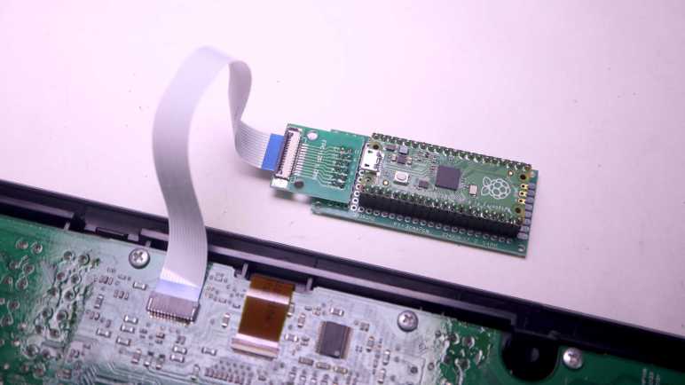
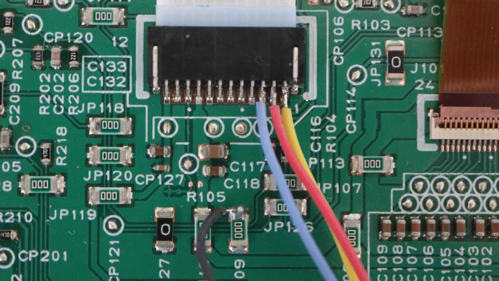
Right now I’m playing with the keyboard module salvaged from a dead Acer Aspire Switch 10. A CircuitPython program running on a Raspberry Pi Pico helped decipher its matrix layout, much more quickly than it would have been for me to figure it out manually with my multi-meter. To test this information, the obvious next step is to turn this into an actual USB HID keyboard. Since I’m already in the realm of CircuitPython, I followed Adafruit’s link to KMK firmware. KMK was written in CircuitPython which means I don’t even have to re-flash the runtime on my Raspberry Pi Pico, I could just change my code.

There are several ways to declare my keyboard matrix, most of the predefined KMK configuration files used the coord_mapping capability to give the keyboard layout in source code a rough resemblance to its physical layout. It’s nice for user-friendliness and ease of customization, but I’m going to skip that step for my initial test. I decided to go with the straightforward keymap list which is strictly in electrical matrix layout, paying no attention to its physical layout. This was easy for me because I had already built the table earlier so I just need to translate it into KMK CircuitPython code:

keyboard.col_pins = (board.GP12,board.GP13,board.GP14,board.GP15,board.GP16,board.GP17,board.GP18,board.GP19)
keyboard.row_pins = (board.GP1,board.GP2,board.GP3,board.GP4,board.GP5,board.GP6,board.GP7,board.GP8,board.GP9,
    board.GP10,board.GP11,board.GP20,board.GP21,board.GP22,board.A0,board.A1)

keyboard.keymap = [
    #12         13          14          15          16          17          18          19          Keyboard pins
    [KC.NO,     KC.UP,      KC.NO,      KC.NO,      KC.NO,      KC.DOWN,    KC.ESCAPE,  KC.NO,      # 1
     KC.BSPACE, KC.DELETE,  KC.RBRACKET,KC.QUOTE,   KC.NO,      KC.NO,      KC.NO,      KC.ENTER,   # 2
     KC.PGUP,   KC.NO,      KC.BSLASH,  KC.PGDOWN,  KC.NO,      KC.NO,      KC.NO,      KC.NO,      # 3
     KC.PSCREEN,KC.INSERT,  KC.EQUAL,   KC.LBRACKET,KC.NO,      KC.DOT,     KC.C,       KC.NO,      # 4
     KC.MINUS,  KC.PAUSE,   KC.NO,      KC.L,       KC.M,       KC.COMMA,   KC.SPACE,   KC.LEFT,    # 5
     KC.F12,    KC.F11,     KC.NO,      KC.N9,      KC.K,       KC.J,       KC.N,       KC.O,       # 6
     KC.F10,    KC.F9,      KC.N8,      KC.N7,      KC.I,       KC.H,       KC.B,       KC.U,       # 7
     KC.F8,     KC.F7,      KC.N6,      KC.T,       KC.G,       KC.V,       KC.NO,      KC.Y,       # 8
     KC.F6,     KC.F5,      KC.N5,      KC.E,       KC.D,       KC.F,       KC.NO,      KC.R,       # 9
     KC.F4,     KC.F3,      KC.N3,      KC.N4,      KC.S,       KC.RIGHT,   KC.NO,      KC.W,       # 10
     KC.F2,     KC.F1,      KC.N1,      KC.N2,      KC.A,       KC.Z,       KC.X,       KC.Q,       # 11
     KC.NO,     KC.NO,      KC.LSHIFT,  KC.SLASH,   KC.NO,      KC.RSHIFT,  KC.NO,      KC.NO,      # 20
     KC.NO,     KC.LCTRL,   KC.NO,      KC.N0,      KC.NO,      KC.NO,      KC.NO,      KC.NO,      # 21
     KC.LWIN,   KC.NO,      KC.NO,      KC.P,       KC.NO,      KC.NO,      KC.NO,      KC.NO,      # 22
     KC.NO,     KC.NO,      KC.NO,      KC.SCOLON,  KC.RALT,    KC.NO,      KC.LALT,    KC.NO,      # 23
     KC.GRAVE,  KC.NO,      KC.TAB,     KC.CAPSLOCK,KC.WINMENU, KC.NO,      KC.NO,      KC.NO,      # 24
     #                                       Special handling required for 19+24 = "Fn" ^^^^^
     ]
]

With this key map, I have a functional USB HID keyboard. (I typed part of this blog entry on it!) This is pretty cool, but it only scratches the surface of what KMK could do. I haven’t fully implemented this keyboard, either. There’s a “Fn” key that activates additional functionality. Fn+F4 has a “Zz” printed on it, and I interpret that to mean putting the computer into sleep mode. I think KMK’s “layer” functionality is how I would go about implementing it, but I went looking for a way to signal sleep key and didn’t find a KC.SLEEP or equivalent. Without that, I don’t have much motivation to figure out layers. A related problem was if I put the computer to sleep, this KMK keyboard does not wake the computer from sleep. I would have to investigate and address that behavior before I can use KMK to help build, for example, a Luggable PC Mark III.

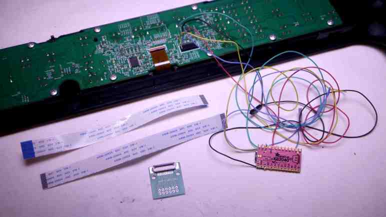
I’ll leave that for the future. I’ve accomplished today’s goal of proving I could turn this salvaged keyboard module into an USB HID keyboard, and I’m satisfied with my answer.

For this hypothetical future project, I assume I will need to build a more compact circuit to replace my jumper wire monstrosity. Maybe even a custom PCB to host both my keyboard connector and my RP2040? Its actual form factor will need be dictated by project needs, which I don’t know right now so I’ll leave things be. While there’s no guarantee I’ll stick with KMK firmware, either, it’s pretty likely as I’ve decided I like CircuitPython a lot.

Acer Aspire Switch 10 Keyboard Matrix

I have a keyboard salvaged from an Acer Aspire Switch 10, and wired up a Raspberry Pi Pico microcontroller with the goal of running “Key Matrix Whisperer“. A CircuitPython program published by Adafruit to help automate the task of probing an unknown keyboard matrix.

To minimize confusion, I lined up pin numbers as much as I can between the keyboard FPC (flexible printed circuit) cable adapter and Pi Pico pin numbers. Adapter pin1 connected to Pi Pico pin GP1, adapter pin 2 to Pico pin GP2, etc. This worked up until pin 22. Because the Pico didn’t expose GP23 or GP24, adapter pin 23 was connected to the next available pin GP26 a.k.a. ADC0 a.k.a. A0 and adapter 24 went to GP27 a.k.a. A1. After creating my wiring harness I plugged it in and ran Key Matrix Whisperer. It worked exactly as advertised listing a pair of pins every time I held down a key.

I printed out a lightened grayscale picture of the keyboard so I can write pin numbers directly on each key. After iterating through all the keys, I learned this keyboard’s 24 wires are used in a 8×16 matrix for a maximum of 128 possible combinations. There were only 83 keys on this keyboard leaving 45 combinations unused. It feels rather inefficient to set up a matrix and use only ~2/3 of possible combinations. Perhaps this keyboard design is a simplified counterpart of a full keyboard that included a numeric keypad and other keys?

I ran Key Matrix Whisperer twice, and all but one key matched up on both runs. Number key 9 reported as 12+22 on my first pass but 6+15 on my second pass. Reviewing the chart, I see 12+22 is the Windows key. I must have accidentally pressed Windows while reaching for 9 on my first pass, and Key Matrix Whisperer registered the Windows key instead of my intended 9. I’m glad I went through a second confirmation pass and caught this mistake.

I don’t know of any keyboard matrix domain specific conventions on which set of pins are rows and which set are columns. By English language convention, columns are laid out left-right and rows are laid out top-bottom. But looking at this particular keyboard matrix, I didn’t notice any particular association between the pins and their physical locations, they seem to be all over the place. For example, pin 1 connects to the up and down arrows which are physically located in the lower right corner. Pin 1 also connects to the Escape key, which is diagonally opposite on the upper left corner. Absent any further understanding of how this matrix was formed, I decided the smaller set of 8 pins are columns for my own convenience: a matrix table that is narrower than it is tall (“portrait” and not “landscape”) is easier to fit here before I put this matrix table to work:

Pin1213141516171819
1UpDownEscape
2BackspaceDel]Enter
3Page Up\Page Down
4PrtSc
SysRq
Ins=[.C
5Pause
Break
LM,SpaceLeft
6F12F119KJNO
7F10F987IHBU
8F8F76TGVY
9F6F55EDFR
10F4F334SRightW
11F2F112AZXQ
20Shift
(Left)
/Shift
(Right)
21Control0
22WindowP
23;Alt Gr
(Right)
Alt
(Left)
24~TabCaps LockMenuFn

Jumper Wire Between Adapter And Pi Pico Skips Breadboard

I bought a FPC (flexible printed circuit) to DIP (dual in-line pins) adapter so I could explore the electrical behavior of a keyboard module I salvaged from a dead Acer Aspire Switch 10. After assembling the adapter, I realized I my original plan would not work. I had thought I could stick it on a breadboard and start with probing its pins with a multimeter and, with information from that probe, use jumper wires to build a test circuit. The first part won’t work because the adapter was designed so its DIP-sde pins were fully underneath without any part poking up above for my probe to touch. The second part won’t work because when the keyboard module FPC is installed, the cable blocks almost the entire left side. There’s enough room underneath if I want to use wires that travel horizontally, but not for the tall vertical ends of the quick test jumpers I had wanted to use.

Researching my options for plan B, I actually found a better way. My plan A of manually probing with a multimeter to determine keyboard matrix would have been a tedious process. I would have to try all combinations of pins and see which pair corresponded to each key. Tedious repetitious processes calls for automation! In this case, I found Adafruit had published a CircuitPython sketch (Key Matrix Whisperer) that would automatically cycle through all combinations of pins looking for continuity as I press individual keys. Wow, this sounds much easier.

To use the Key Matrix Whisperer I would need to wire up my keyboard adapter to a CircuitPython microcontroller. I was going to use the Adafruit KB2040 I had been using for CircuitPython experimentation, because the “Kee Boar” was originally designed for the scenario of building custom keyboards. Unfortunately it had only 20 accessible IO pins and I needed 24 here. So I pulled out my Raspberry Pi Pico with its 26 accessible pins already soldered with header pins. The new connection solution is to skip the breadboard and build a wiring bundle to directly connect adapter board to Pi Pico.

These jumper wires (*) came with individual 0.1″ pitch connectors. (I’ve seen these connectors listed as Dupont connectors, which is far too generic of a name.) While I could connect directly one-by-one, that implied a nightmare of single wires popping loose and having to figure out where they should go back to. In the interest of keeping things better organized, I popped off most of those single connectors and slotted them into longer connectors. (*) (The specific box I bought also called the connector type as JST-SM, except they are very clearly NOT JST-SM.) This only took a few extra minutes and I felt holding things together more securely was a good time investment. I don’t want to worry about loose connections as I decipher this keyboard matrix.


(*) Disclosure: As an Amazon Associate I earn from qualifying purchases.

Proto Advantage FPC Connector DIP Adapter (FPC080P030)

I want to learn more about a keyboard module I pulled out of an Acer Aspire Switch 10. And while the first step is to look at the actual wires involved in connecting such a thing, to get further I will need to probe electrical behavior of those wires. I went online to find a breakout board that I hoped would help me, and ordered a Proto-Advantage FPC080P030. (*) One side of this board has 0.8mm pitch contacts with flexible sizing able to accommodate up to 30 positions. Appropriate for soldering the kind of FPC (flexible printed circuit) cable connector I unsoldered from the Acer’s circuit board, which has 26 positions.

The business card that came with the kit pointed me to website for Proto-Advantage, where I found a huge catalog of adapter boards to bridge the world of surface-mount devices and 0.1″ pitch prototype perforated boards/breadboards. Looks like I am likely to buy more of their products in the future if I continue playing with salvaged electronics components. I went to check out their listing for the FPC080P030 I just bought. This is a company based in Canada. For their United States customers like myself, looks like it makes more sense to use Amazon logistics for distribution rather than trying to sell direct.

First task was to double check I bought the correct pitch to match my salvaged connector.

I was not looking forward to soldering 0.8mm pitch connectors one by one, but it turns out I didn’t have to. My soldering iron tip is far too big to work at this scale but all I had to do was drag a melted blob of solder across this row of pins. Between the solder mask on the Proto Advantage circuit board and copious use of soldering flux, surface tension did all the hard work. A quick meter check confirmed I have electrical continuity on all 26 pins and there were no bridges. Thanks, surface tension!

For the other side, there were no through-holes for adapting to 0.1″ pitch DIP format. I didn’t quite understand what I saw on product listing pictures but it made sense once I had all components in hand. The backside pads were laid out to go with right-angle 0.1″ headers, with their angled head pointing in alternate directions.

Proto Advantage bundled this assembly helper circuit board. There’s no copper to solder to here, its purpose is to hold all pins in a row within its drilled holes. This ensures all pins are soldered with the correct relative spacing to fit on a 0.1″ grid.

This specific board is, unfortunately, not breadboard jumper friendly. Inserting the keyboard module FFC would block off almost the entire left side. There’s a tiny bit of room to lay wires flat against the surface of the breadboard, but it won’t be possible to explore with jumper cables like I wanted. I’ll have to find another way, and it turned out to be a better way.


(*) Disclosure: As an Amazon Associate I earn from qualifying purchases.

Acer Aspire Switch 10 Keyboard Wiring

I want to experiment with turning a salvaged laptop keyboard module into a USB HID keyboard. My test subject is this keyboard pulled from an Acer Aspire Switch 10. I have successfully unsoldered its connector in the hopes I can solder it onto a breakout board I had ordered. While I wait for the board to be shipped to me, I can do a little scouting.

The easiest observation was that 2 out of 26 pins appear to be unused. They are present at the flex cable connector but immediately disappear into nothingness.

The remaining 24 wires are seen going into the keyboard module underneath a piece of black fabric tape. Peeling that tape off may gain more insight, but I’m not going to. Flex cables can only flex a finite number of times before something breaks, so I’m trying to keep handling and manipulation to a minimum.

Examining the circuit board, I looked for traces that are significantly wider than others or maybe wires that span multiple pins in parallel. Both are typical indications of power or ground wires, but I didn’t see anything of the sort. I then looked for components like decoupling capacitors or current-limiting resistors, and didn’t notice any good candidates either. This is consistent with my memory this keyboard was not backlit.

Looking on the back side, I see very few wires and they are mostly consistent with wires jumping over other perpendicular wires on the front. Not all of the vias lined up with traces I could see, which would be consistent with a circuit board with more than two layers. Though there are traces I couldn’t see, I think it is possible all 24 wires are connected directly to the chip adjacent to the now-unsoldered connector.

I read the chip marking as IT8595E-128 and the logo matches that of Taiwan-based ITE Tech, Inc. But there’s no IT8595E-128 listed on their product website today. The closest I found is an IT8596 under “Notebook product line”, advertised to be a laptop peripheral controller. Sounds about right, but there’s no datasheet download for me to see if it might be a sibling of this IT8595. Perhaps IT8595 is a discontinued product, or perhaps it was a custom design exclusive to Acer. Either way, I’m not going to get any more information here. To get any more information on how this keyboard module is wired, I will need to wait for my adapter board to arrive.

Dusting Off Acer Aspire Switch 10 Keyboard

Getting a tiny version of “Cat & Galactic Squid” running seemed like a good stopping point for my CircuitPython exploration with a Canon MX340 control panel. Now I want to go back and further explore CircuitPython’s keypad library. It included a KeyMatrix class for scanning large button matrices such as those used on a keyboard, which reminded me of a past project idea: repurposing a laptop keyboard. They are nice and compact, designed for easy integration into tight spaces, but they weren’t designed to be easily reused beyond the original laptop. I’ve disassembled several retired broken laptops and I’ve wished to turn them into compact USB keyboards. Maybe KeyMatrix can finally make that idea a reality.

Looking over my pile of salvaged components awaiting reuse, the best candidate (it was on top) was the keyboard I extracted from a broken Acer Aspire Switch 10. I liked how this small keyboard felt when I typed on it, and believed it would be good to put back in use.

While I can (and have in the past) soldered wires directly to flexible printed circuit (FPC) metal contacts, life would be much easier if I can use a real FPC connector. I used my handy Digi-Key PCB ruler to measure a pitch of 0.8mm. Given my recent discovery of vendors selling FPC connector breakout boards, I searched for 0.8mm pitch 26-pin breakout boards. Sadly, that combination was not popular enough to have a breakout board with pre-populated connector. The closest I found was a 0.8mm pitch breakout PCB with no connector but could accommodate up to 30 pins. (*)

I would have to either buy my own 26-pin connector or try to reuse the one I had. Since I like to salvage and reuse, I’m trying the reuse option first. The circuit board was placed on my MHP30 mini hot plate (*) and brought up to temperature.

The white plastic latch started to turn brown by the time solder melted, but all plastic components still seemed to be in their proper shape when I lifted this connector free. I think this is good enough for a try. If I fail with this connector, then I’ll spend money to buy another.

With the connector freed, and the breakout board ordered, I explored the wiring involved.


(*) Disclosure: As an Amazon Associate I earn from qualifying purchases.

Tiny Cat & Galactic Squid on MX340 LCD

I’ve verified that I now have full CircuitPython programmatic control over all input and output functionality available within the control panel of a Canon Pixma MX340 multi-function inkjet. The point of the exercise was to see if I could get this far. I would love to repurpose this control panel for a future project, but that is secondary. The perfect project would be one that needs a small LCD, numeric keypad, and a handful of task-dedicated buttons and LEDs. While I wait for such a project to come up, I could have some fun with a less serious project.

My friend Emily created Cat and Galactic Squid for me to use as demonstration content of my ESP32 composite video output library. I love this colorfully cheerful animation and have used it as test subject for several other projects. However, the MX340 LCD is monochrome and has only 196×34 pixels so I could not use the original cat & squid directly. I had to downscale it in an image editor, and manually fix up all the broken edges from such drastic down-sampling. And while I’m switching to monochrome, the cat is now modeled after one of Emily’s current cats “Hobie” with a suitable black and white tuxedo pattern. Getting the handful of pixels to remotely resemble a cat required that I go online to search for “pixel art cat” for some guidance.

There weren’t enough pixels to convey movement, so cat and squid would remain static. Neither were there enough pixels for that Saturn-like planet and a galaxy in the background, so the simplified version will only have vaguely circular dots of different diameters moving at different speeds for a parallax effect. Ideally I could use CircuitPython’s sprite bitmap compositing engine displayio to put all these elements together. Unfortunately I couldn’t figure out how to make this LCD compatible so I wrote my own crude compositing routine.

I originally thought I’d write this as an entirely separate MX340 demo app, but I realized I could incorporate it into the existing key echo feedback test app: a “screen saver”! Monochrome LCDs don’t really have burn-in issues that need saving, but it’s an user experience paradigm I can leverage. I switch to this animation if there aren’t any key presses for a while, and switch back as soon as a key is pressed. Integrating cat & squid was a nice bonus bit of CircuitPython practice.

https://github.com/Roger-random/canon_mx340/tree/main/control_panel_circuitpython

MX340 Control Panel Under RP2040 Control

I bought some FPC (flexible printed circuit) cables and connector breakout boards from Amazon vendors so I no longer have to solder wires directly to my salvaged Canon Pixma MX340 multi-function inkjet control panel. The first FPC breakout board went on a perforated prototype board to host a Raspberry Pi Pico. Up until this point I had been using Adafruit’s KB2040 board. But since they’re both based on RP2040 chip and have CircuitPython support, switching my code to run on a Pi Pico is a minor task of changing over a few pin names.

Soldering to the FPC breakout board with its 0.1″ (~2.54mm) pitch was far easier than the 1.0mm pitch of soldering directly to the control panel. Which meant I finally got around to connecting five wires that were previously not connected:

  1. 5 volt DC wire to supply WiFi LED
  2. LED+ for Power LED, in series with an 100 ohm current-limiting resistor already on board.
  3. LED+ for Alarm LED, also with resistor.
  4. Power button that is pulled to ground when pressed.
  5. Stop button that is pulled to ground when pressed.

My CircuitPython code had provision to set the appropriate bit flags to manipulate the WiFi LED, but I hadn’t tested it until this point due to lack of +5V power. I was happy to see it worked, but I doubt I would find a use for it. As it originally shined into a clear plastic light guide and thus pointed in an opposite direction from the rest of the control panel.

And I hadn’t dealt with the remaining four wires at all, as I considered the two direct-wired buttons and two direct-wired LEDs fairly standard microcontroller fare. And indeed, there were no surprises after I declared two CircuitPython digitalio pins for those LEDs and a keypad instance to read (and debounce) those two buttons. All worked as expected on the first try.

I updated my test app to toggle power LED upon presses to the power button, and the same for alarm LED and the stop button. The “In Use/Memory” and WiFi LEDs blink their own separate heartbeat patterns. And the LCD displays status of key matrix scan code activity: every time one of the K13988-scanned button is pressed, its name is displayed on the LCD. It makes for a simple demo to prove I have complete control over all electronic functionality of this salvaged control panel. Now this control panel waits for a project that could put it to good use but while it’s waiting, I went ahead with a project that puts it to silly fun use.

FPC And Breakout Boards For MX340 Control Panel

I’ve been using my salvaged Canon Pixma MX340 multi-function inkjet control panel as test target hardware for learning CircuitPython. After exposing a keyboard event queue, my first attempt at a CircuitPython library is now feature-complete. Well, it is on the software side. The hardware side still need help but I’ve recently learned it is a problem I can solve by spending money.

Up until this point, I had been exploring control panel communications by soldering wires to the back side of its FPC (flexible printed circuit) cable connector. This was essential because I still need the cable installed for main logic board and control panel to talk to each other. Now that I have a code library to let any CircuitPython microcontroller take the place of the main logic board, it means I can actually use my own cable and avoid the need to solder any more wires to these pins.

There are vendors on Amazon selling breakout boards for popular FPC sizes, so I searched for 12-pin 1.0mm pitch FPC connector breakout to see my options. Some of these listings were for a bare circuit board, so I picked this one (*) as it had the connector already soldered and its output pins were spaced out in a prototype board friendly 0.1″/2.54mm pitch format. Those output pins were also already numbered, which I wanted even though it made the next step a bit harder.

I then searched for a short piece of FPC I can use to connect my salvaged control panel with the breakout board. There were again multiple vendors offering 1.0mm pitch 12-position cables, with 150mm being a popular length. I just had to choose if I wanted “A-type” (*) with metal contacts on the same side of the ribbon on both ends, or if I wanted “B-type” (*) with metal contacts on opposite sides of the ribbon. And here I got stuck. I didn’t know which side the breakout board’s connectors made their metal connections. If I chose wrong, I could flip the board over to make the connection, but that would mean the pin numbers would become reversed. That is a recipe for confusion and potentially project-killing mistakes. After waffling back and forth for a while, I decided on the solution of buying both sets. I felt spending a few extra dollars was worth the guarantee of consistent pin numbers.

Once the products arrived, a little probing indicated A-type was the correct answer for me to wire up a Raspberry Pi Pico microcontroller board.


(*) Disclosure: As an Amazon Associate I earn from qualifying purchases.

Sparky Danger Organ Now On The Autopian

Discovering I can just treat Sparky Danger Organ like a piezo buzzer for making music was great, it opened up a world of already-written Arduino sketches playing music with tone(). Now Sparky is getting its 15 minutes of fame with Emily’s This Is How Electronic Ignition Works And Also How To Make A Spark Plug Play Music published on The Autopian.

In Emily’s article, she compared modern electronic ignition with electromechanical ignition from BC (before computers) era of cars. The distributor diagram is a pretty good explanation why I couldn’t do very much with an old ~1950s Chrysler ignition coil my neighbor had sitting on a shelf: I needed something to interrupt power to the ignition coil so its primary winding’s 12V field can collapse and induce high-voltage in its secondary winding. Since I usually play with electronics manipulating 5V or less, at well under 1A, I didn’t have anything on hand suitable to handle such power.

However, a modern electronic ignition coil has that switch built-in. (The “Igniter” box in the LS1 Coil diagram of Emily’s article.) So to repurpose a retired coil+plug only requires a 5V, low-current, digital control signal to be sent on its IGT pin. Now that’s something Arduino tone() can do easily and help Sparky find its singing voice.

So what’s next? There was a bit of confusion between Emily and I about Arduino tone(). She referred to an installed library, but I found it as a built-in function. Investigating this confusion led me to https://github.com/bhagman/Tone where I learned we were both right. There’s a full non-core version that Emily had to install into her (presumably older) Arduino IDE, and Arduino had incorporated a simplified version of this library into core which is what I found. The simplified version can only generate one voice. The full version can generate more voices: one per hardware timer on the AVR chip. ATmega8-based chips have two timers so two voices. ATmega328P (like that on the Arduino Nano I used) can do three voices, and an ATmega1280-based board like the Arduino Mega can control six spark plugs. Useful facts to keep in mind whenever Emily or I get our hands on more retired electronic ignition coils.

MX340 CircuitPython Key Events

My CircuitPython learning project was to communicate with the K13988 chip on board a salvaged Canon MX340 multi-function inkjet control panel. The follow-up project, currently in progress, is to convert my jumble of experimental and exploratory code into something resembling an usable library. It looks pretty good after I rearranged all the setup/cleanup into context manager syntax, but then I realized I was missing a big piece: key press events. I had been printing key codes to serial terminal as they come in, but that was no way to write an API!

For precedence I looked into CircuitPython keypad class. I had expected this to be an opportunity to learn about Python events and event listeners, so I was surprised (and mildly disappointed) to find an event queue that client code is expected to poll on a regular basis. Well, at least I know how to implement such a thing, and Python standard libraries should make it pretty easy to implement.

I could reuse their Event class to report my key press events, but the EventQueue class itself is locked away inside Adafruit implementation and not available to me. I went looking for an existing Python standard library queue and the first search result seemed to be far more complex than I had expected. Turns out that particular queue was designed for coordination across threads, overkill for this purpose. I just need the basic deque (double-ended queue) class to emulate most of Adafruit’s EventQueue.

For my first draft I decided against implementing a separate object to expose keyboard event queue. I’ll expose a get_key_event() method which should serve basic scenarios well enough until I see justification to do more.

MX340 CircuitPython: Internals and Context Manager

I’ve got CircuitPython code to interface with control panel of a Canon MX340 multi-function inkjet, and gradually refining my crude experimental code into an actual reusable CircuitPython library. Using events for synchronization and exposing property setters was just the start.

A major change is to separate communication infrastructure from code that utilizes such infrastructure. For example, I’ve had code in there blinking the “In Use/Memory” LED to let me know everything is still running. I consider code to transmit the LED control bytes to the NEC K13988 as infrastructure, and the timing loop to toggle LED on and off to be application code. I have a separate asynchronous task that continually updates the LCD content for the same reason, and that should be separated out as well. During the experimental phase I could just mix code in there in a big jumble. A global space where any bit of code can call any other bit of code. But now I have to think about which methods should be part of the API and which are internal implementation.

To reflect this division, a minor change is to rename several methods with a leading underscore. This is a “weak internal” indicator by Python convention. They are understood to be for internal use though there’s no language level mechanism preventing callers from accessing them. I guess this means they can be changed without becoming a public API breaking change? Reading the linked section of PEP 8, I saw there’s also a way to declare public interface with __all__. As per Python tutorial on module imports, this works in conjunction with “from [module] import *“. I don’t understand enough about Python modules yet to know if it’s applicable to my project.

After I performed this separation, I can clearly see a set of startup and cleanup tasks that have to run before and after application code. This sounds like a job for context managers! I can set up all the infrastructure by using an async with statement, and all application code can run within its scope. I first tried to write my context manager with the generator syntax that has a single yield for application code, but that failed: I need to decorate such a generator with @contextmanager to apply supporting infrastructure from contextlib, which has not been ported to CircuitPython. Oops! Fortunately I can still implement a context manager by falling back to using special method names __aenter__() and __aexit__(). Once implemented, I can apply even more lessons from my recent study session, implementing a clean separation between my test code from my NEC K13988 infrastructure.

I was pretty pleased with myself with how well this is going when I realized I completely forgot about key press events.

MX340 CircuitPython Refinements: Async Event But No Property Setter?

I’ve been writing CircuitPython code to interface with the NEC K13988 chip on board a salvaged Canon MX340 multi-function inkjet control panel. At first I only intended to explore if it was even possible to repurpose the panel. Now that I’m confident it is possible, I decided my follow-up would be to factor my code to extract a reusable library that could potentially support multiple projects. As expected, the task of making the code neater taught some valuable lessons.

Asynchronous Event

I had a few asynchronous tasks declared and running, each handling one aspect of K13988 interface, but sometimes they stepped on each other’s work. I learned about Lock() earlier but I had additional synchronization needs that didn’t fit a Lock(). Some pieces of code needed to wait for certain other startup conditions to be met before it ran. For example, I needed to wait for the K13988 to wake up enough to send data bytes before I could successfully transmit commands to it.

In the constructor, I set a boolean:

self.in_startup = True

And in my data transmission code, I check that boolean value in a loop:

while self.in_startup:
    await asyncio.sleep(0)

That would put data transmission on hold until I receive my first byte from K13988, at which point I could flip that boolean value:

# First successful read complete, exit startup mode
self.in_startup = False

This worked, and I guess it isn’t terrible. But there was a better way. When I read through Python documentation during my study session, I discovered this pattern fit Event from the asyncio library.

Using events, I declare one in the constructor:

self.transmit_startup = asyncio.Event()

And in my data transmission code, I will wait for this event before proceeding:

await self.transmit_startup.wait()

Permission to proceed will happen once I receive my first byte from K13988:

# First successful read complete, exit startup mode
self.transmit_startup.set()

This was a simple case, and I’m glad it helped me learn to add to my toolbox so I am ready to tackle more complicated scenarios in the future.

No Async Property Setter?

This control panel has four LEDs. Two are wired directly to main logic board connector pins, two are controlled by K13988. I thought I would add Python property setters for those two LEDs, following precedence of setting a CircuitPython digitalio output pin value. But it seems like I can’t expose a property setter to turn a LED on like this:

k13988.in_use_led = True

The problem is that such LED update would require sending two command bytes to K13988, and that is an asynchronous operation which meant I have to somehow declare async on the property setter and somehow use await in the caller. If there’s a Python syntax to declare such a thing, I couldn’t find it. For now the best I can do is to implement an explicit method to set LED:

await k13988.in_use_led(True)

Not terrible, just not as straightforward. I can live with this while I learn more asynchronous Python and maybe I will learn something that’ll let me come back to fix this later. In the meantime I have more cleanup work to do.

Updated Goals for MX340 CircuitPython Project

I typically learn new things by alternating between hands-on time and reading study time. After reading through (though not necessarily understand all of) several Python Enhancement Proposals ending with PEP 492 Coroutines with async and await syntax I’m ready to switch back to playing in a code editor. My CircuitPython practice project is to interface with a control panel I salvaged from a Canon MX340 multi-function inkjet. I’ve successfully accomplished that with a few rough test programs, but I didn’t understand what I did, thus the study session.

Now that I understand a bit more of Python generally and CircuitPython in particular, I want to aim higher for my project. Instead of a bunch of test code written on the fly whenever the next idea occurs to me, I should go in and organize things sensibly. I want to learn from Adafruit’s collection of CircuitPython libraries to interface with hardware peripherals, following their lead to reorganize my MX340 jumble into a self-contained piece of reusable code. I believe the primary reference would be Adafruit’s CircuitPython design guide for community-contributed libraries. I don’t understand all of it yet, but I expect to learn by doing and learn from my failures to conform to the design guide. I do not realistically expect my MX340 CircuitPython library to be used by many others. The point of the exercise is to learn how to build such a library, so that a future library I write may actually be useful to others.

Here are my updated goals:

  1. A class to handle serial communication with the NEC K13988 chip on board the control panel, with three functional areas:
    • Buttons: Event queue of button activity, following precedence of Adafruit’s keypad class.
    • LEDs: Two boolean properties with get/set to manipulate LEDs under K13988 control.
    • LCD screen: following precedence of Adafruit’s rgbmatrix class, either create a byte array for raw frame buffer or use a caller-allocated byte array. Implement a refresh() method which will initiate sending frame buffer data to K13988 for display.
  2. An optional class to wrap the above LCD raw byte array into a MicroPython-style FrameBuffer class. Implemented as adafruit_framebuf with a custom frame buffer manipulation class. This is optional and not part of #1 because the caller may wish to manipulate the byte buffer directly.
  3. Some example code utilizing the above.
  4. After writing example code, decide if it’s useful to add one more: An optional class as single point of contact for the entire control panel. Exposing a single event queue integrating direct-control buttons (“Power” and “Stop”) with K13988-scanned buttons, and properties for direct-control LEDs (“Power” and “Alarm”) peer of K13988-controlled LEDs (“WiFi” and “In Use/Memory”)

That seems like a set of achievable goals to guide me as I got started with code reorganizing.

Notes on PEP 492 Coroutines with async and await syntax

As I’m reading through several Python Enhancement Proposal (PEP) documents, I have to keep in mind that I don’t have to understand everything on my first read through. And I also have to keep a goal in mind so I don’t get too distracted. For this session, the motivation was copy/pasting “async with” from example code without having any idea what those keywords meant. PEP 380 was the last in my list of self-assigned prerequisite readings, but now it’s time for the main attraction: PEP 492 Coroutines with async and await syntax. After completing this study session, I have a much better understanding of what “async with” does.

It was interesting to follow Python evolution on this front. My prerequisite PEP reading all discussed generators and coroutines as a specific type of generator. In PEP 492 they laid out the reasons for separating out coroutines as its own concept. The underlying implementation of coroutines still uses many pieces of generator infrastructure, but the language will now treat them as different things. As part of this evolution, a large part of this document discussed is devoted to “Design Considerations” of alternative approaches, and “Transition Plan” for maintaining compatibility with pre-492 coroutine syntax.

One decision I found disappointing was that debugging features are disabled by default. I understand the motivation to ensure debugging features do not impact production code, but I think leaving them out completely is going too far. Beginners who most need feedback from Python runtime are not going to know they need to set an OS environment variable PYTHONASYNCIODEBUG.

But I am in full support of another decision: there’s no comprehension shorthand:

Syntax for asynchronous comprehensions could be provided, but this construct is outside of the scope of this PEP.

I don’t like Python comprehension shorthands and I’m glad there to see this PEP did not add one. It’s possible this text meant only exactly what it says, but in my professional career I’ve used “out of scope” as a polite rephrase of “I don’t like this idea and I’m not doing it.” It made me smile to think the PEP author might be doing the same here.

Reading through PEP 492 concludes this particular study session, and the knowledge informed updated goals for my MX340 CircuitPython project.

Notes on PEP 380 Syntax for Delegating to a Subgenerator

I’ve dipped my toes into writing Python code for asynchronous execution, and encountered a lot of new concepts that I felt I need to study up on. One of the keywords I wanted to understand better was “with“, which took me to context managers. Another item on the list of mystery was “yield from“. I recently learned “yieldin the context of coroutines, and I knew “from” in the context of loading Python modules, but they didn’t make sense together. Thankfully I found PEP 380 Syntax for Delegating to a Subgenerator, where my confusion was explained by the fact it had nothing to do with loading modules.

When I read up on coroutines, it took effort for my brain to absorb the concept of code execution interleaved between caller and callee. It was a foreign enough concept my brain didn’t flag a consequence of Python’s special treatment: the “yield” relationship is limited to one layer of interaction. What if we wanted to refactor a chunk of code, that included a “yield“, into another coroutine? Things quickly get messy. If only there’s a way to extend yield to multiple levels, and this is the problem PEP 380 wants to solve with “yield from“:

The rationale behind most of the semantics presented above stems from the desire to be able to refactor generator code.

Reading through the PEP, I was not happy to see “StopIteration” exception was used to convey a return value out of “yield from“. I was taught in the school of “exceptions should be exceptional” and here it is just a normal non-exceptional code return path. My initial reaction was tempered by learning StopIteration is how Python iterators (which are used all the time) signal a halt. I think my instinctive negativity came from experience with languages where exception handling incurs a significant performance overhead. Judging from what I’ve learned here, either Python exceptions incur no significant penalty or Python designers feel it is an acceptable cost.

For what it’s worth, I was not alone in my negative impression. Using StopIteration to convey return value was also disclosed under “Criticisms” sections of PEP 380 and dismissed as “without any concrete justification”. Shrug. But I was thankful another criticism was dismissed: looks like there was a suggestion to use syntax of “yield *” and I’m glad it didn’t go in that direction because it’d end up as another special syntax very difficult to look up. Searching on * would be a disaster as it is popularly used as a query wildcard character. From this perspective “yield from” is far superior and it only meant typing three more characters. I’m much happier with this approach and I’m glad to see it as I continue my PEP study session with PEP 492.

Notes on PEP 343 The “with” Statement

I don’t like Python shorthands that are so short, it leaves a beginner up a creek without any keywords they could use for searching and learning. But I’m OK with shorthands that clean up code while still leaving something for a beginner to look up. Such is the case with PEP 343 The “with” Statement. I’ve been using “with” in Python for a while, but never really sat down to understand what’s going on when I do. Thankfully there is a keyword I could use to find appropriate documentation.

My introduction was in the context of example #2:

with opened("/etc/passwd") as f:
    for line in f:
        print line.rstrip()

Opening a file for data operations, “with” guarantees all cleanup will also be handled behind the scenes. PEP 343 explains the problems it intended to solve, and explaining how this convenience is handled behind the scenes. There were two explanations that I could follow. The first explains using an implementation specified with a set of methods with special names “__enter__()” and “__exit__()“. I understood Python will look for these names under conditions specified in PEP 343. Then the same concept was rewritten in a way that built upon PEP 342: a context manager called upon via with can be implemented as a generator that calls “yield” at a single point within a “try/finally” block. This neatly packages all associated components together. Any setup code runs before “yield“. Within the “try” block, “yield” hands control over to client code. (In the above example, the “for” loop reading text in a file line by line.) Then code inside either “except:” or “finally:” can cleanup after client code completes.

I like this pattern, ensuring setup and cleanup code can be kept together while allowing other code to run in between them. While I have not yet fully absorbed Python generators, I think I understand enough of this particular application to appreciate it.

Coverage of this topic in the official Python tutorial is under “Predefined Clean-up Actions” within the “Errors and Exceptions” section. As appropriate for a tutorial, it focuses on how to use it and how it’s useful and leaves all the history and design thinking and implementation nuts and bolts to PEP 343.

Next lesson: what did it mean when I saw yield from” instead of just “yield?

Not A Fan Of Python Succinct Syntax

When learning about a Python feature like coroutines and generators, I found it instructive to flip back and forth between different ways a feature is represented. It’s nice to get the context of a feature and its evolution by reading its associated Python Enhancement Proposal, and it’s good to see how the official Python tutorial presents the same concept after the PEP process was all said and done. However, I want to take a side detour because the generator tutorial section was immediately followed by generator expressions and that made me grumpy.

Some simple generators can be coded succinctly as expressions using a syntax similar to list comprehensions but with parentheses instead of square brackets.

I am personally against such alternate syntax for the reason they are extremely hostile to people who don’t already know it. When I came across a generator and didn’t know what it was, I was able to search for keywords “yield” and “send” and get pointed in the right direction. But if someone comes across a generator expression or a list comprehension and didn’t know what it was, they have nothing to search on. The expression is enclosed by parentheses or square brackets, commonly used throughout the language. Inside the expression are normal Python syntax, and searching on “for” would just get to those features and not anywhere close to an explanation for generator expression or list comprehension.

I get that whoever pushed this through Python loved the option to “code succinctly” but my counter position is: No! Go type a few more characters. It won’t kill you, but it’ll be tremendously helpful to anyone reading your code later.

Here’s an excerpt from the list comprehension section of Python tutorial:

[(x, y) for x in [1,2,3] for y in [3,1,4] if x != y]

As a Python beginner, I had no idea what this syntax meant when I first saw it. I see two “for” loops, but this isn’t just a “for” loop, I see an “if” statement, but I didn’t know what that decision affected. (There’s no obvious “then” in this if/then.) Beyond those keywords, there are just variables and parentheses and square brackets. I had nothing to put into a search to point me towards “list comprehension”.

Python list comprehension tutorial said the above was equivalent to this:

combs = []
for x in [1,2,3]:
    for y in [3,1,4]:
        if x != y:
            combs.append((x, y))

If I didn’t understand this code, I could search “for” and learn that. Same with the “if“, and I can see the result of the decision affected whether the value was appended to a list. This is way more readable, it wasn’t even that much more typing.

Was list comprehension (and generator expression) worth adding to Python? I guess enough people in decision-making positions thought yes, but I disagree. I don’t understand why Python is considered beginner-friendly when horribly beginner-hostile things like this exist. I don’t think they should be in the language at all, but that ship has long since sailed. I can only shake my fist, yell at cloud, then return to my study.


Related: I made a similar rant on impossible to search JavaScript short hands

Arduino tone() Can Play Sparky Danger Organ

I got a spark plug to sing a song, but it was singing out of tune and I didn’t know why. I barely know enough about music to get this far. My friend Emily had more sheet music reading skill and offered to double-check my music translation. If her translation sounds good, then we’ll know the problem was my sheet music translation. If her translation also sounds odd, we’ll know the problem is with my timing code controlling spark frequency.

I replaced my version of the song with hers, and it sounded great! So that’s settled: Sparky’s first performance sounded bad because I didn’t know how to read sheet music. I also received feedback that the way I represented music in my Arduino code was peculiar. No argument from me, because I wrote it out of ignorance and it was what I could hack together at the time. Emily then asked if there was a reason why I’m not using tone() if I’m using an Arduino anyway. The answer was that I didn’t know it existed.

Prompted by this question, a bit of searching on “Arduino tone library” found a GitHub repository at https://github.com/bhagman/Tone, whose README explained it was a library to use AVR timers to generate 50% duty cycle square waves of a specified frequencies along with a list of #define that mapped musical notes to frequencies. It also said a single-timer version of the library has been incorporated into Arduino core, so for single-voice applications like Sparky we wouldn’t even need to install an additional library.

I thought the 50% duty cycle (half of time signal is on, half off) might be a problem, because I’ve been using 0.5ms signal pulses and leaving the pin off the rest of the time. I looked in the tone library but wasn’t familiar enough with AVR timer configuration registers to understand how I might convert it over. Then I remembered the always-useful mantra: check the easy thing first. Maybe Sparky doesn’t mind if the trigger pulse was longer.

Since the single-timer version of tone was now built into Arduino, I looked for Arduino built-in examples illustrating its use. I found “Examples/02.Digital/toneMelody” which was designed to work with a piezo buzzer. I pointed it to Sparky’s IGT pin and heard it play the little melody. Great! Sparky doesn’t mind longer IGT pulses and I can throw out all of my hacked-up music-hampering playback code and just use tone(). I don’t even need to struggle with sheet music or convert them to MIDI notes anymore, I can play songs other people have already translated for tone() playback. I found several collections and the first collection with its own take on Beethoven’s “Ode to Joy” is https://github.com/robsoncouto/arduino-songs. I gave to Sparky and yeah, way better than my version and a lot easier too. I wish I knew tone() existed a few days ago, but at least I know now. This tone() music earned Sparky 15 minutes of fame on The Autopian.

Notes on PEP 342 “Coroutines via Enhanced Generators”

I think I’ve worked my sparkly distraction out of my system, time to return to my Python study. This was motivated my CircuitPython experiments running on RP2040 microcontrollers. CircuitPython may be a reduced subset of Python, but it nevertheless incorporated many concepts that I have yet to grasp. Thus the study session, which dug through multiple PEP (Python Enhancement Proposal) design documents. Here are my notes after reading PEP 342 Coroutines via Enhanced Generators.

I was not familiar with coroutines, but I found a helpful explanation within Python glossary: “Coroutines are a more generalized form of subroutines. Subroutines are entered at one point and exited at another point. Coroutines can be entered, exited, and resumed at many different points.” I was familiar with functions, which has a single entry point and multiple exit points. (Each return is an exit.) When I read about “resume” in context, my first thought was of a function calling another. The parent caller function pauses execution waiting for the child callee function to run. Which is true, but Python coroutines have more points of interaction with each other. The caller can send additional data to the callee, which receives that data via yield. And they each maintain their internal state while this went on.

Why do we even want this? At surface I thought the same could be accomplished by standard nested loops, but example #2 in the PEP (JPEG contact sheet creator) helped me understand. Yes, maybe the pattern of execution could be replicated by nested loops, but that meant a single function has to track all variables involved in every nested loop. A coroutine, in contrast, can be written to encapsulate information for just one layer.

Here’s my pseudocode to replicate example #2 with nested loops:

for each page of contact sheet
  for each thumbnail on contact sheet
    for each JPEG
      generate thumbnail
    add thumbnail to contact sheet
  write page of contact sheet

If I want to process a bunch of JPEG differently, resulting in a different summary output JPEG, I would write a new function that has the different second loop but has the same innermost and outermost loops. With coroutines, I can get the same result by swapping out the thumbnail_pager coroutine and continue using the rest without making any changes to them or duplicate code.

I think I see the advantage here for independent code modules, but it’ll take a while for my brain to adapt and add this tool to my toolbox. During this transition period I’m likely to continue writing my code as nested loops. But at least this understanding helped me understand Python context managers. But before that, a complaint from grumpy Python student.