I’m playing around with a retired Denso ignition coil-on-plug pack. After gaining a marginally better understanding of its limitations, I will convert my test circuit to a proof of concept discussed with my friend Emily Velasco (who gave me this thing to play with): make it into a silly music instrument I’ve named Sparky Danger Organ.
This ignition coil came out of a Toyota Sienna’s V6 engine which probably redlines somewhere around 7000 RPM. At 7200 RPM this coil would be firing sixty times a second, but 60Hz is on the low side for music-making. So my workbench experiments were to find out how much faster I can drive this thing and I think it’s somewhere between 1 kHz and 1.5 kHz. (There isn’t an exact number because sparks fade out rather than abruptly cut off.) But judging from Wikipedia’s list of piano notes and their frequencies, even a limit of 1kHz should be enough to represent an interesting range of music notes.
Putting all that together gave Sparky Danger Organ its first performance, and it’s definitely along the lines of a bear riding a bicycle: the novelty is not that Sparky Danger Organ is a great music instrument, but that it can make an attempt at all. There’s only a very limited range of frequencies where it sounds like an acceptable tone, and even within that range the music does not sound great. I may have made mistakes translating piano sheet music into Arduino code. Or maybe the frequency I generated is not what I had intended to generate, throwing the instrument out of tune. The top suspect along these lines is the possibility Arduino framework is doing work behind the scenes and adding delays throwing off the output frequency.
Despite those potential problems, it was a successful proof of concept. Emily has some ideas on how to troubleshoot this device. [UPDATE: the solution was to throw away all of my crappy code and use Arduino tone().] And if we ever get our hands on one or more engine’s worth of ignition coils, there may be a Sparky Danger Orchestra.
Experiment to control a Denso ignition coil-on-plug module was far more successful than I had expected. It was a lot of fun! Because high voltages are involved (the very core purpose of an ignition coil…) the first round was done on my garage floor, away from most of my electronics components and equipment. Now that I have gained some confidence it won’t send sparks shooting everywhere, the test rig was moved to my workbench to get some measurements.
These numbers won’t be very good, though. It would be better if I can get an idea of what parameters are important to an ignition coil and what values to expect from a data sheet, but I had no luck finding such official engineering information. Searching for “Denso 90080-19016” found many auto parts suppliers offering to sell me more of those units and/or non-Denso substitutes, but no details beyond which cars the part would fit. Furthermore, this ignition coil was retired from a Toyota Sienna due to error codes relating to the ignition system, so it is probably not functioning to spec anyway.
Its power supply requirement is my biggest unknown. I had tried connecting it to a lithium-ion battery power pack delivering approximately 12 volts, but its power protection circuit believed there was a short circuit and cut power. My bench power supply has a red LED indicating “amperage limit reached”. When using it to power my experiment circuit, that red LED blinks every time the coil fired a spark. So clearly this coil has a brief but very high current draw. As a digital logic person, my understanding of solving such problems only went as far as “add capacitors”. I had some salvaged electrolytic capacitors available and connected them. I installed so much that the inrush current upon plugin would trigger power protection even before the coil started firing. If I disconnect power while running the coil, I can hear those capacitors supply enough to spark three or four times (each less energetic than the last) before fading out. And even with these capacitors, the brief current draw is still high enough to trigger errors. I’m either not using the right types of capacitors, or of the wrong values, to smooth this out. Such is my ignorance of proper electric power system design.
I had thought if the power requirements were simple enough, I could power the whole thing with a USB power bank. With a boost converter to kick USB 5V up to supply the coil at 12V. But given these high draw symptoms, I am skeptical an Amazon lowest-bidder DC boost converter will survive this coil’s demands. I will continue using a lead-acid battery that has (so far) tolerated such abuse.
The next set of experiments concern IGT signal duration. My experiments started with 2ms as a value I eyeballed from a blurry oscilloscope screen capture. If I want to drive this coil faster, I need to know how short of an IGT pulse I can get away with. I modified my Arduino sketch to use the knob to adjust signal duration, and output the current duration to one of my less-precious computers. The results were:
2ms: initial guess that worked.
~1ms: start to hear a difference in the sound of the spark.
~0.8ms: sound of spark is weaker, and I no longer see IGF LED blink. So the coil thinks the spark is no good beyond this point to run an engine. Thankfully I’m not running one.
~0.4ms: even weaker spark sound, and spark generation becomes intermittent.
~0.2ms: no spark at all, just worrisome whining noises from the coil.
Those are the duration of IGT signal pulses with the caveat that I measured these with a constant 17ms (“redline”) between pulses. As the time between pulses shrink as well, it affects behavior in response to IGT signal pulse. The two variables are related, but I don’t understand exactly how. And without a good way to quantify results it’s not very feasible for me to map out a 2D graph charting how those two variables interact.
Lacking such metrics for better understanding, I settled on a maximum of IGT pulses 0.5ms in duration, and 0.5ms between pulses. In other words, an 50% duty cycle square wave at a frequency of 1kHz. Referencing Wikipedia’s chart of piano note frequencies, an upper limit of 1 kHz should still be enough for a bit of silly fun.
The problem with deciding I need to sit down and do some reading is that I’m vulnerable to get distracted by something shiny. Or in this case, something sparkly. Some time back I learned how voltage boost converters worked for laptop screen LED backlights. A little after that, it occurred to me ignition coils in modern electronic ignition engines must be boost converters as well. Except instead of driving a bunch of LEDs in series, an ignition coil raises the car’s 12V DC up high enough to jump across a spark plug gap. I thought it might be fun to try driving a coil in a non-automotive context and discussed the idea with other local makers. I was too cheap to buy a new coil just for this experiment, because I knew eventually someone would replace their car’s ignition coil and I can ask for the old one. That day has come: my friend Emily Velasco let me know she was going to stop by with a Denso ignition coil-on-plug module with associated spark plug, recently retired from her parents’ Toyota Sienna.
Research
The first step is information gathering. Thanks to ubiquity of Toyota vehicles, Emily found a pinout diagram for the ignition coil. This module has four pins. Two for power (+12V DC and ground) and two for signal (IGT and IGF). Toyota’s official workshop service information would have more details on its operation and troubleshooting, but I don’t have access to that. Fortunately there are other web resources like TOYOTAtech’s How to Find Toyota Ignition System Faults Fast! Dotting the IGFs and Crossing the IGTs.
According to this page “IGT” (I guess “ignition trigger”) is a signal from ECU telling the coil to do its thing, and “IGF” (guessing “ignition feedback”) is a signal from coil back to ECU to signal successful operation. Both operate with +5V DC logic. IGT is usually at ground level and briefly raised to +5V by the ECU to call for spark ignition. Looking at the blurry oscilloscope screen capture on TOYOTAtech’s page, my best guess is raised for approximately 2 milliseconds. In contrast, IGF is usually up at +5V DC and the coil pulls it low for roughly 1 millisecond to signal successful spark generation. This open-drain system allows multiple coils to share a common IGF line back to the ECU.
Circuit Board
Armed with this knowledge, I built a quick experiment circuit out of components immediately available at my workbench. Emily helped me by making a connector as CAD practice, for which I was thankful. My board’s output side needs to interface with that connector. On the input side, I needed two voltage levels: +12V DC for the coil and +5V DC for the signal. I have a 3S Lithium-Ion battery pack for 12-ish volts, but its battery management system (BMS) freaked out at the workload. As a backup, I switched to an old-fashioned lead-acid battery. For 5V I used the most expedient thing: an Arduino Nano with its USB socket and +5V DC output pin. To run the coil it will be connected to a cheap disposable USB power bank instead of a computer.
The experiment circuit had two input paths to IGT, switchable by a jumper. The first path is a “manual override” test mechanism with a small push-button switch. Once everything is hooked up, a push on the switch will raise IGT to +5V DC. If there is no spark, we have to backtrack and see what went wrong. If there is a spark, I can move the jumper to the other input path: pulse-generating Arduino Nano.
I’ve already established it needs to raise the line to +5V for approximately 2 milliseconds, but how long should it wait between pulses? A Toyota Sienna should idle somewhere just under 1000 RPM, and redline somewhere around 7000 RPM. This coil is responsible for a single spark plug. As a four-stroke piston engine, it would need to spark once every two revolutions of the crankshaft. The math then works out to: 1000 revolutions/minute * 1 minute/60 seconds * 1 spark/2 revolution = ~8.3 sparks/second. Invert that value to arrive at 120 milliseconds between sparks. Doing the same math for 7000 RPM arrives at 17 milliseconds between sparks. So I would expect this coil to reliably spark once every 120ms to 17ms. For the default program, I programmed the Arduino to raise IGT to +5VDC for 2ms then wait 120ms before repeating.
Coil Arrives
I started building the experiment board immediately after Emily told me she would stop by, hoping to have something ready by the time she arrived. So it was slapped together with speed as the utmost priority and everything else (visual neatness, design elegance, and… ahem… electrical safety) relegated to be dealt with later. We connected the coil’s four wires to my test circuit, and it was time for the moment of truth.
I tapped the switch, and we saw a spark. Woohoo! We powered down the system and moved the jumper. Once powered back up, the Arduino sent its pulses and we have a steady stream of sparks. Success!
Enhancements
I honestly expected a lot more debugging before getting to this point, so I didn’t have anything else prepared. Emily suggested that we connect a potentiometer to the system for interactivity, so out came the soldering iron and associated tools. Emily has built a lot of projects with potentiometer knob adjustments so she handled that addition. As the code monkey I updated my Arduino code to read knob position so we can adjust from “1000 RPM idle” to “7000 RPM redline”.
Emily also fixed a problem with my board: I had connected a LED to IGF but it stayed dark. Reviewing the circuit I realized out of habit I had set it up to shine whenever IGF is high: but the coil never raises IGF to high! It pulls IGF low to report a successful spark. Emily added a 1k pull-up resistor and rewired the LED so it shines when IGF is low.
We connected everything back up and the adjustment knob worked wonders. We can “rev up” our system and it was fun, with Emily capturing a few video clips. Unfortunately the IGF LED stayed dark, but it didn’t dampen our enthusiasm. Now that the coil is up and running under conditions approximating its designed purpose, we enter the “screwing around” phase pushing it beyond original operating range.
Adventuring Beyond Spec
Emily asked for a fluorescent tube, but my house had almost entirely converted to LED lighting. I had but a single remaining tube and it was only still there because I haven’t figured out how to open up its enclosure. Emily figured it out in five seconds and pulled out the tube, connecting its ends in place of the spark plug. The ignition coil was able to act as a (poor) fluorescent tube ballast dimly flashing the tube. (The room had to go dark for Emily to shoot that video.)
After this fluorescent tube experiment, we reinstalled the spark plug and made a fascinating discovery. With no other (intentional) changes, the IGF LED now blinks in sync with sparks as originally expected. We have no idea why. Perhaps something about the workload of driving a fluorescent tube? This coil and plug was replaced because the Toyota Sienna’s engine control unit (ECU) reported codes for ignition issues. It’s possible cylinder combustion was working properly but poor IGF reporting triggered the malfunction indicator light (MIL). We agreed if this was the case, it obviously meant Toyota/Denso must add a fluorescent tube to their official list of repair tools.
Emily tried to see if this spark can light a sheet of paper on fire. There was a lot of glowing, charring, and pitting, but it took persistence before she got a real flame. There are far more effective ways to start a fire! But it did make us wonder if it’d be practical to build a crude electrical-discharge machining (EDM) system out of an ignition coil. That idea has been added to the ever-growing project to-do list.
The most promising experiment was revving this thing far beyond “redline” by shortening time between pulses below 17ms. To go even faster, we reduced the duration of IGT pulse itself. This quickly extinguished the IGF LED, which was the coil’s way to complain things are going too fast for a good combustion-initiating spark. But that’s OK, because we’re not here to ignite air-fuel mixtures, we were trying to turn it into a silly and pointless musical instrument. Still, there was a limit. We started losing the spark (and our musical note) when we went too fast. Exactly how fast is too fast? To make further progress on this front I’ll have to better characterize parameters of this ignition coil-on-plug module.
I’ve been playing with CircuitPython for my latest microcontroller project, and so far I’ve been impressed by how well it brings Python benefits (like managing asynchronous execution) to modest hardware. But taking full advantage requires person writing the code to know how to leverage those Python benefits. I’ve had experienced Python developers say my Python code reads like C code, failing to take advantage of what Python has to offer. I think it’s a valid observation! But I don’t learn well reading a long spec end to end. I need to write some code in between reading documentation to give context for the concepts I’m reading. Some code, some documentation, back to code, repeat.
And I think my CircuitPython adventures have reached a good stopping point. My motivation is to better understand what I’ve been using to deal with asynchronous serial data transmission and reception between my microcontroller and the NEC K13988 chip in charge of a salvaged Canon Pixma MX340 multi-function inkjet control panel. I got as far as creating an instance of asyncio.lock and calling “async with” that lock. I copied that straight from sample code and it was an opaque magical incantation to me. While I understood the high level concepts of synchronization, I have no idea how Python language syntax used those keywords. So, time to pause coding and hit the books!
One of the great things about Python is that its evolution takes place out in the open. Many features can be traced back to a corresponding design document called a Python Enhancement Proposal. A PEP distills information from many sources. Discussions on mailing lists, forums, etc. While design of a Python feature is usually summarized in a PEP, not all PEP intend to add Python features. PEPs are used for other things including best practice procedure recommendations for Python contributors. For example, I was amused by the fact that PEP #1 is for PEP itself, PEP Purpose and Guidelines.
A PEP for a feature will typically refer to precedence and possibly alternate proposals for that feature. This ancestry tree of PEPs is great for learning how a feature came to be. Sometimes a feature directly builds upon another, sometimes a feature has no direct technical relationship to another but the syntax is designed so existing Python developers will find it familiar. It also tends to mean I have to at least skim those earlier PEPs to understand what the current PEP is talking about. It will take effort to not get too distracted.
I think getting through this trio will give me a good start. A single step in the long journey to make my Python code look like Python and not just C code translated to Python syntax. Unfortunately, I have a hard time staying focused on study time.
I have built up a rough set of CircuitPython code that sends a bitmap to show on LCD screen of a salvaged Canon Pixma MX340 multi-function inkjet. I abandoned my effort to get sprite compositing via displayio, but I still want to do something fun with this screen. As an experiment, I wrote a loop that continuously sent LCD frames to display, exploring its theoretical ~14fps top speed. The result was very jerky, and CircuitPython console output showed a lot of my error message indication transmission failures that had to be retried.
The first data point was adding a small delay between frames to see if that changes behavior. It did not, so I believe these failures were not caused by a relentless nonstop stream of frames. The next data point was to remove my heartbeat LED, and that stopped the stream of errors. Interesting.
The heartbeat LED is a separate task, with asyncio switching back and forth between LCD updates and heartbeat LED updates. Heartbeat is a simple loop that blinks the “In Use/Memory” LED on and off by transmitting corresponding control flags. Each toggle is a two-byte transmission, but the LCD screen update is a much longer sequence of data transmissions.
Task switching could occur at any await statement, which means it is possible for heartbeat LED update command to barge in the middle of a LCD sequence. The most inconvenient time would be right after the 0x04 0xC4 command “Bulk transfer of 196 bytes incoming”. If the next transmission is a two-byte LED toggle instead of the expected 196 byte transfer, everything would understandably go awry.
To prevent interleaving data transmission between tasks, I need to add a locking mechanism so heartbeat LED updates will hold off until LCD screen update is complete. And in case of continuous nonstop LCD animation, it needs to make sure heartbeat LED update gets a chance in between frames. Out of habit I started writing my own locking mechanism but then realized I was being silly. I went to read documentation and confirmed a lock is already available as asyncio.Lock. I only had to create a single instance of the object, then as per documentation add an “async with” statement on that instance to prevent my two data transmission tasks from stepping into each other’s sequences.
It worked! I could put my heartbeat LED back into the system, spin the LCD animation updates to full speed, and they both run. No longer interrupt each other and causing transmission errors. But this experience really gives me a feeling I’m wielding powers beyond my comprehension. I barely understand async/await and now I’m adding “with” context management which I also barely understand. This is probably a good time to pause my uninformed code-slinging and read some tutorials and/or specifications to understand what’s going on.
After a small (if not necessarily elegant) enhancement to adafruit_framebuf class, I can use it for basic graphical operations on the bit-mapped LCD of a salvaged Canon Pixma MX340 multi-function inkjet control panel. I then set my sights on adapting it to work with Adafruit’s graphics compositing engine displayio, but that turned out to be more difficult than I had thought.
I don’t know the full history but looking in hindsight I think displayio was optimized for sprite rendering, the most performance-critical part of a 2D game engine. Such a system would support products like Adafruit PyGamer. Not so important for this inkjet control panel LCD, whose refresh rate tops out at just under 14 frames per second. But I thought it would be fun anyway.
Adafruit has displayio drivers for their most popular screens and obviously my LCD is none of them. Looking for an appropriate tool, I found their framebufferio class which takes a frame buffer and returns a display object. Its target usage scenario allows using displayio with a RGB LED matrix, which has resolutions with similar order of magnitude as my LCD. This looks promising.
When I fed framebufferio my FrameBuffer class, I crashed my KB2040 which restarted in safe mode. (Indicated by triple blinking yellow LED.) Annoyingly, when a CircuitPython device crashes and reboots like this, Mu closes its serial terminal so I couldn’t read the error message before it immediately disappeared. I had to bring in a different serial monitor tool in order to see the error:
TypeError: 'FrameBuffer' object does not support 'protocol_framebuffer'
Darn. Looks like the CircuitPython frame buffer object I had been working on, isn’t the CircuitPython frame buffer object expected by framebufferio. If I want this to work, I have to implement “protocol_framebuffer“, but what is it? Clicking on the link brought me to something called circuitpython_typing.FrameBuffer, which forwards to rgbmatrix.RGBMatrix. I added methods to my FrameBuffer-derived class in order to match those listed for RGBMatrix, but that was not good enough.
Digging deeper meant going into core CircuitPython written in C. I found framebufferio/FrameBufferDisplay.c which had this line:
I think this is where my error message came from, so the next step is to find more information on the expected protocol which was declared in the associated header file FrameBufferDisplay.h.
This is beyond my current understanding of CircuitPython code. Does it mean framebufferio only works with Adafruit’s own frame buffer objects written in C? Or is this compatible with user-created Python code somehow? Again I tried modifying my FrameBuffer-derived class to fit this signature, but either I made a mistake somewhere or it is fundamentally impossible. I wish I could get finer-grained error message telling me where exactly I failed to support protocol_framebuffer, but I just keep getting the same failure leaving me stabbing in the dark.
After a few hours of fiddling without success, I abandoned displayio compatibility and wrote up this page in case my future self wants to pick up where I left off today. Without displayio I’ll learn what I can from using adafruit_framebuf. First lesson: updating LCD at a high frame rate required task synchronization.
I’m playing with a LCD screen built inside the control panel I salvaged from a Canon Pixma MX340 multi-function inkjet. I tried using CircuitPython’s adafruit_framebuf library for drawing operations. Out of all supported frame buffer formats, the closest is MVLSB but those bits are in reversed order. I added code to reverse bits, which put a picture on screen but the real solution is to add proper buffer format support.
I was encouraged by adafruit_framebuf‘s description in its documentation: “CircuitPython pure-python framebuf module, based on the micropython framebuf module.” If this library was itself implemented in Python, I should be able to figure something out. Clicking “Edit on GitHub” link on the upper right, I was brought to the GitHub repository for adafruit_framebuf and I quickly found source code file for the module.
At the top of adafruit_framebuf.py are a series of classes, each representing one of the supported buffer formats and implements four static methods: set_pixel(), get_pixel(), fill(), and fill_rect(). I found the implementation for MVLSBFormat and it looks like it’s within my skill level to copy it and reverse its bit manipulation operators to create a MVMSBFormat counterpart. The next problem is: how do I use my custom MVMSBFormat class with the FrameBuffer class? FrameBuffer‘s __init__() assigns a format class in response to initialization parameter, and it raises a ValueError() if it doesn’t recognize the parameter.
That’s when I remembered I am still thinking like a C/C++ programmer and Python doesn’t have a concept of private properties. I could create an instance of FrameBuffer for MVLSB format, and then immediately replace the .format property to point to my MVMSBFormat class. As a C/C++ programmer, this feels extremely icky. Is this the correct Python-ic approach? I doubt it, but I don’t know the right way. So right or wrong this is what I have now.
With my FrameBuffer.format pointing to my MVMSBFormat class, adafruit_framebuf drawing operations render correctly on screen without the need for bit reversal utilities. As a bonus, eliminating bit reversal overhead also meant I could draw text again without encountering “RuntimeError: pystack exhausted“. I think that’s good enough to declare victory with basic bitmap operations and move on to a sprite compositing engine.
Once I found and fixed a missing command within my initialization sequence, I have gained full programmatic control over the LCD screen of a control panel I salvaged from a Canon MX340 multi-function inkjet. The main point of the exercise was to learn, because it’s a relatively simple black-and-white screen 196 pixels wide by 34 pixels tall and not terribly exciting on its own. Still, now that I know how to send it frame buffer data… what can I do with it?
I’m not interested in re-implementing standard graphics routines myself, so I went looking for one already available. While learning about MicroPython I recall coming across mention of a framebuf utility class for basic graphical operations on a frame buffer. As a fork of MicroPython, Adafruit has a corresponding CircuitPython implementation named adafruit_framebuf so I thought I’d take a look.
One of the frame buffer byte formats supported is called MVLSB. The M stands for monochrome, and the V means each byte represents a vertical column of eight pixels. LSB means least significant bit is the highest pixel, and the most significant bit is the lowest. This is very close to what I have on hand except for the bit order. On this screen, the least significant bit is the lowest pixel and they go up from there.
This is the result of drawing a diagonal line from upper left (0,0) to lower right (195,33). Since bit order is reversed within each byte, each horizontal stripe of data gets rendered vertically inverted from what they are supposed to be.
Drawing text results in gibberish when it crosses stripes. But if I position the text so it sits entirely within a single stripe, the result is legible as vertically inverted text. “Hello Framebuffer” in this case.
I could write some code to laboriously step through each bits in a byte and generate a bit-reversed counterpart value, but since there are only 256 possibilities, a lookup table would be much faster at the expense of a bit of memory. I went online looking for such a lookup table and found one in this Stack Overflow thread: Efficient Algorithm for Bit Reversal (from MSB->LSB to LSB->MSB) in C.
I modified that lookup table from C to Python syntax, and used it to reverse a stripe of frame buffer data before transmitting it to the LCD. Now my diagonal line renders as expected. Unfortunately, text rendering now fails with “RuntimeError: pystack exhausted“. This was unexpected. The lookup table itself would have consumed at least 256 bytes, and there’s an additional 196 bytes of working buffer for me to perform bit reversal on a single stripe. I didn’t think I was skating close to RP2040 limits yet here we are. Also, it’s not a general out of memory error, but specifically about call stack size and the bit reversal mechanism didn’t increase the call depth at all. Weird!
Well, reversing bits was just a hack anyway. The right approach is to add support for this byte format directly so convoluted bit reversal workaround becomes unnecessary. And it restored text rendering, too.
I had incorrectly configured asynchronous serial communication parameters between my KB2040 microcontroller running CircuitPython and NEC K13988 chip on a control board salvaged from a Canon MX340 multi-function inkjet. But once I sorted that out (two stop bits, not just one) I could successfully send a full set of frame buffer data to the LCD with minimal transmission failures. This allowed me to follow up on an observation I had from my first test: the vertical frame buffer byte offsets are not as expected.
The pattern I saw via logic analyzer indicated the top 8 pixels of the screen were dictated by sending pixel data with the offset 0x4D to start the sequence. But when I tried doing the same thing with my KB2040, the stripe rendered two pixels lower than expected. This pattern continued for the rest of the screen, with successively lower rows corresponding to 0xCD, 0x2D, and 0xAD. When I decoded frame buffer data captured by logic analyzer, offset 0x6D dictated the bottom-most two rows of pixels. (The least significant six bits are not visible.) However, now data sent to 0x6D is not visible at all. Experimenting with other offsets, I stumbled on the fact I could transmit data to 0x8D and that data would help me fill in the top two rows of pixels. (The most significant six bits are not visible.)
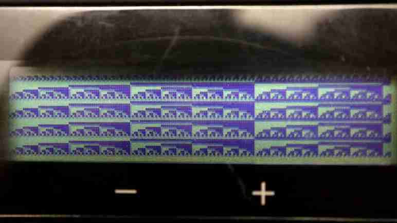
Even though it was unexpected, that was good enough for my next experiment: I changed the program so instead of a fixed value, each byte counts up one. This gave me get a precise delineation and count for all horizontal and vertical pixels. Thanks to this test pattern I am now confident this LCD has 196 pixels horizontally and 34 pixels vertically.
But what about that unexpected offset? The most likely suspect is a mistake in my initialization sequence, and a double-check found the culprit. There was a two-byte sequence 0x04 0x42in my decoded notes, but I forgot to put that in my KB2040 initialization sequence. Once I put that back in, my LCD frame buffer renders at the expected location. On my to-do list is to play with my initialization sequence, selectively skipping them to see what effect they have on behavior. Looks like I inadvertently started that experiment early! This little side trip also suggested an interesting possibility: that the LCD controller has extra frame buffer memory available, possibly allowing vertical scrolling without re-sending the entire frame buffer.
I’ve got an Adafruit KB2040 microcontroller connected to a control panel salvaged from a Canon MX340 multi-function inkjet. Using CircuitPython busio.uart, I’m trying to emulate MX340 main logic board with my KB2040, communicating with the NEC K13988 chip on board the control panel hoping to access its capabilities. I saw some initial success, but I had to retry many data transmissions which hinted something was amiss. I forged onward to get more data about what might be wrong.
The first experiment was to test my hypothesis that the first LCD update sent by MX340 main board was a “clear screen” sequence. I sent 0x04 0xF5, the command I suspect to be “start displaying data from frame buffer”, but without transmitting the clear screen sequence of zeroes. I was rewarded by an awakened LCD displaying gibberish, proving the command and “clear screen” data hypothesis.
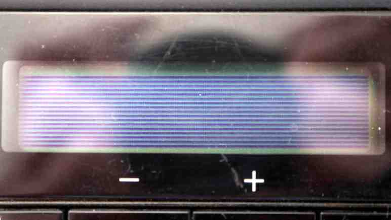
Pulling up my notes on decoding LCD frame buffer data, I followed that pattern to transmit a single stripe of 0x55 as frame data. Hexadecimal 0x55 translates to binary 0b01010101 and I expected this to show up as four horizontal lines across the screen. The first few attempts failed, with no visible change and no 0x20 acknowledgement byte. Then a transmission went through with visible change and 0x20 acknowledgement, but it looks wrong.
Instead of four horizontal lines all the way across, the line is broken as it hopped up and down across the screen. The fact that it came up on screen at all told me I’m very, very close but there’s definitely a problem. At every byte (vertical slice of 8 pixels) there was supposed to be an alternating sequence of bright and dark, but I see several sections where two white pixels separate black pixels, and less frequently two dark pixels side by side without a white pixel separating them.
What might cause these off-by-one-bit errors? My first guess was that the baud rate sent by KB2040 was a tiny bit off from what the control panel expected, so I tried 250001 baud and 249999 baud but that just made things worse. Even parity and 8 data bits had to be correct or I wouldn’t have gotten this far, leaving stop bits as the final parameter. I changed my busio.uart configuration from 1 stop bit to 2 stop bits and that seemed to have been the answer.
Running with 250000 8E2, I could reliably send five full stripes of 0x55 for a screen full of clean horizontal lines. This makes sense in hindsight. When I examined logic analyzer trace one byte at a time, I wouldn’t have seen anything obviously differentiating between 2 stop bits or just 1 stop bit and delay between each byte of transmission. A mistake that went unnoticed until now. However, I still see the occasional transmit failure, so there might be another bug still lurking. I hope to get more data about it as I continue my experiments.