“Learn Enough Command Line to Be Dangerous” notes

leclThe Ruby on Rails Tutorial was a great way for developers like me to get up and running with no prior Rails experience. However, it does require the reader to have some level of computer software skill so complete beginners could still get lost.

Acknowledging this, the author Michael Hartl has taken on the challenge of getting people up and running in the world of software development under the umbrella of his venture “Learn Enough Society” with a series of titles in the pattern of Learn Enough [X] to Be Dangerous.

I was curious about how his approach, so even though I’m not the target audience I spent some time looking it over.

His idea of starting from Ground Zero is the command line, which I agreed was a fair place to start. The reader is taken through the basics of navigating files and directories and is introduced to some basic command line utilities such as grep.

I applaud the focus on repeatedly prodding the reader to use the man command to learn more information. The manual pages displayed by man were written by programmers for programmers, which meant they tend to be densely packed with jargon difficult to pierce even for experienced users. But that’s where the information is, so one has to dive in to find answers. The tutorial tries to ease readers into man pages by teaching how to search for specific information so the reader is not overwhelmed trying to understand the full text. Baby steps.

Not being the target audience, I can’t judge how effective the tutorial is. I’m sure there are problems that didn’t stand out to me because I already knew the information, almost certainly because it didn’t stand out to the author either.

I did notice one example, though: The tutorial used the computer term argument without explanation. This might cause confusion: “I don’t want to argue with anybody, I just want to learn the command line!” (UPDATE: I e-mailed the author about this observation, and he has added explanations to the tutorial. Very cool.)

The Cost for Security

In the seemingly never-ending bad news of security breaches, a recurring theme is “they knew how to prevent this, but they didn’t.” Usually in the form of editorializing condemning people as penny-pinching misers caring more about their operating cost than the customer.

The accusations may or may not be true, it’s hard to tell without the other side of the story. What’s unarguably true is that security has some cost. Performing encryption obviously takes more work than not doing any! But how expensive is that cost? Reports range wildly anywhere from less than 5% to over 50%, and it likely depends on the specific situations involved as well.

I really had no idea of the cost until I stumbled across the topic in the course of my own Rails self-education project.

I had designed my Rails project with an eye towards security. The Google ID login token is validated against Google certificates, and the resulting ID is salted and hashed for storage. The code for this added security were deceptively minor, as they triggered huge amounts of work behind the scenes!

I started on this investigation because I noticed my Rails test suite ran quite slowly. Running the test suite for the Rails Tutorial sample app, the test framework ran through ~120 assertions per second. My own project test suite ran at a snail’s pace of ~12 assertions/second, 10% of the speed. What’s slowing things down so much? A few hours of experimentation and investigation pointed the finger at the encryption measures.

Obviously security is good for the production environment and should not be altered. However, for the purposes of development & test, I could weaken them because there would be no actual user data to protect. After I made a change to bypass some code and reducing complexity in others, my test suite speed rose to the expected >100 assertions/sec.

Granted, this is only an amateur at work and I’m probably making other mistakes doing security inefficiently. But as a lesson to experience “Security Has A Cost” firsthand it is eye-opening to find a 1000% performance penalty.

For a small practice exercise app like mine, where I only expect a handful of users, this is not a problem. But for a high-traffic site, having to pay ten times the cost would be the difference between making or breaking a business.

While I still don’t agree with the decisions that lead up to security breaches, at least now I have a better idea of the other side of the story.

Protecting User Identity

google-sign-inRecently, web site security breaches have been a frequent topic of mainstream news. The technology is evolving but this chapter of technology has quite some ways to go yet. Learning web frameworks gives me an opportunity to understand the mechanics from web site developer’s perspective.

For my project I decided to use Google Identity platform and let Google engineers take care of identification and authentication. By configuring the Google service to retrieve only basic information, my site never sees the vast majority of personally identifiable information. It never sees the password, name, e-mail address, etc.

All my site ever receives is a string, the Google ID. My site uses it to identify an user account. With the security adage of “what I don’t know, I can’t spill” I thought this was a pretty good setup: The only thing I know is the Google ID, I can’t spill anything else.

Which led to the next question: what’s the worst that can happen with the ID?

I had thought the ID is something Google generated for my web site. More specifically my site’s Client ID. I no longer believe so. A little experimentation (aided by a change in Client ID for the security issue previously documented) led me to now believe it’s possible the Google ID is global across all Google services.

This means if a hacker manages to get a copy of my site’s database of Google ID, they can cross-reference to databases of other compromised web sites. Potentially assembling a larger picture out of small pieces of info.

While I can’t stop using Google ID (I have to have something to identify an user) I can make it more difficult for a hacker to cross-reference my database. I’ve just committed a change to hash the ID before it is stored in the database. Salted with a value that is unique per deployed instance of the app.

Now for a hacker to penetrate the identity of my user, they must do all of the following:

  1. Obtain a copy of the database.
  2. Obtain the hashing salt used by the specific instance of the app which generated that database.
  3. Already have the user’s Google ID, since they won’t get the original ID out of my database of hashed values.

None of which are impossible, but certainly a lot more effort than it would have otherwise taken.

I think this is a worthwhile addition.

Limiting Google Client ID Exposure

google-sign-inToday’s educational topic: the varying levels of secrecy around cloud API access.

In the previous experiment with AWS, things were relatively straightforward: The bucket name is going to be public, all the access information are secret, and none of them are ever exposed to the user. Nor are they checked into the source code. They are set directly on the Heroku server as environment variables.

Implementing a web site using Google Identity got into a murky in-between for the piece of information known as the client ID. Due to how the OAuth system is designed, the client ID has to be sent to the user’s web browser. Google’s primary example exposed it as a HTML <meta> tag.

The fact the client ID is publicly visible led me to believe the client ID is not something I needed to protect, so I had merrily hard-coded it into my source and checked it into Github.

Oops! According to this section of the Google Developer Terms of Service document, that was bad. See the sections I highlighted in bold:

Developer credentials (such as passwords, keys, and client IDs) are intended to be used by you and identify your API Client. You will keep your credentials confidential and make reasonable efforts to prevent and discourage other API Clients from using your credentials. Developer credentials may not be embedded in open source projects.

Looks like we have a “secret but not secret” level going on: while the system architecture requires that the client ID be visible to an user logging on to my site, as a developer I am still expected to keep it secret from anybody just browsing code online.

How bad was this mistake? As far as security goofs go, this was thankfully benign. On the Google developer console, the client ID is restricted to a specific set of URIs. Another web site trying to use the same client ID will get an error:

google-uri-mismatch

IP addresses can be spoofed, of course, but this mitigation makes abuse more difficult.

After this very instructional detour, I updated my project’s server-side and client-side code to retrieve the client ID from an environment variable. The app will still end up sending the client ID in clear text to the user’s web browser, but at least it isn’t in plain sight searchable on Github.

And to close everything out, I also went into the Google developer console to revoke the exposed client ID, so it can no longer be used by anybody.

Lesson learned, moving on…

Adventures in Server-Side Authentication

google-sign-inThe latest chapter comes courtesy of the Google Identity Platform. For my next Rails app project, I decided to venture away from the user password authentication engine outlined in the Hartl Ruby on Rails Tutorial sample app. I had seen the “Sign in with Google” button on several web sites (like Codecademy) and decided to see it from the other side: Users for my next Rails project will sign in with Google!

The client-side code was straightforward following directions in the Google documentation. The HTML is literally copy-and-paste, the JavaScript needed some reworking to translate into CoffeeScript for the standard Rails asset pipeline but wasn’t terribly hard.

The server side was less straightforward.

I started with the guide Authenticate with a Backend Server which had links to the Google API Client Library for (almost all) of the server side technologies including Ruby. The guide page itself included examples on using the client library to validate the ID token in Java, Node.JS, PHP, and Python. The lack of Ruby example would prove problematic because each flavor of the client library seems to have different conventions and use different names for the functionality.

Java library has a dedicated GoogleIdTokenVerifier class for the purpose. Node.JS library has a GoogleAuth.OAuth2 class with a verifyIdToken method. PHP has a Google_Client class with a verifyIdToken method. And to round out the set, Python library has oauth2client.verify_id_token.

Different, but they’re all in a similar vein of “verify”, “id”, and “token” so I searched the Ruby Google API client library documentation for those keywords in the name. After a few fruitless hours I concluded what I wanted wasn’t there.

Where to next? I went to the library’s Github page for clues. I had to wade through a lot of material irrelevant to the immediate task because the large library covers the entire surface of Google services.

I thought I had hit the jackpot when I found reference to the Google Auth Library for Ruby. It’s intended to handle all authentication work for the big client library, with the target completion date of Q2 2015. (Hmm…) Surely it would be here!

It was not.

After too many wrong turns, I looked at Signet in detail. It has a OAuth2::Client class, which sounded very similar to the other libraries, but it had no “verify” method so every time I see a reference to Signet I keep deciding to look elsewhere. Once I decided to read into the details of Signet::OAuth2::Client, I finally figured out that it had a decoded_id_token method that can optionally verify the token.

So it had the verification feature but the keyword “verify” itself wasn’t in the name, throwing off my search multiple times.

Gah.

Nothing to do now but to take some deep breaths, clear out the pent-up frustration, and keep on working…

Simple Online Digital Photo Frame

The CarrierWave Playground project was created for experimentation with image upload. As intended, it helped me learn things about CarrierWave such as creating versions of the image scaled to different resolutions and extracting EXIF image metadata.

Obviously the image has to be displayed to prove that the upload was successful. I hadn’t intended to spend much time on the display side of things, but I started playing with the HTML and kept going. Logic was added for the browser to report its window size so the optimal image could be sent and scaled to fit. I had a button to reload the page, and it was fairly simple to change it from “reload the current page” to “navigate to another page”. Adding a JavaScript timer to execute this navigation… and voila! I had myself a rudimentary digital photo frame web app that loads and displays image in a sequence.

It’s fun but fairly crude. Brainstorming the possibilities, I imagine the following stages of sophistication:

Stage 1 – Basic: Where I am now, simple JavaScript that performs page navigation on a timer.

Problem: page blinks and abruptly shifts as new page is loaded. To avoid the abrupt shift, we have to eliminate the page switch.

Stage 2 – Add AJAX: Instead of a page navigation, perform a XMLHttpRequest to the server asking for information on the next image. Load the image in the background, and once complete, perform a smooth transition (fade out/fade in/etc.) from one image to the next.

Problem: Visual experience is at the mercy of the web browser, which probably has an address bar and other UI on screen. Also, the user’s screen will quickly go dark due to power saving features. To reliably solve both, I will need app-level access.

Stage 3 – Vendor-specific wrapper: Every OS platform has a way to allow web site authors an express lane into the app world. Microsoft offers the Windows App Studio. Apple has iOS web applications. Google has Android Web Apps.

Unknown: The JavaScript timer is a polling model, do we gain anything by moving to a server-push model? If so, that means…

Stage 4 – WebSocket: Photo updates are triggered by the server. Since I’m on Rails, the most obvious answer is to do this via WebSockets using Action Cable.

Looking at the list, I think I can tackle Stage 2 pretty soon if not immediately.

Stages 3 and 4 are more advanced and I’ll hold off for later.

EXIF fun with CarrierWave uploader

To play with the CarrierWave uploader gem I created a new Rails project just for the purpose of experimentation. I had thought about doing this as part of the Hartl Rails Tutorial sample app but ultimately decided to keep things as bare-bones as I can.

When trying to understand a new system, a debugger is a developer’s best friend. Part of this exercise is to get my feet wet using a debugger to poke around a running Rails app. The Hartl Rails Tutorial text introduced the byebug gem but only minimally covered usage. The official Rails Guides had more information which helped me get going, in addition to various users writing up their own cheat sheets.

I decided to dig into image metadata. Basic information such as width and height were made available as img[:width] and img[:height] but where are the others? With the help of byebug I found that they were available in the img.data hash. Most of the photography-specific EXIF metadata are in there as well, though somebody interested only in that subset can access it via the img.exif hash.

As an exercise I decided to try to pull out the original date. Time stamp on digital photography files have always been a headache. Most computer OS track “Created Date” and “Modified Date” but they are relative to the computer and not reliable for photo organization purposes. Photo editing introduces another twist: if an image is created from a photograph, the time stamp would be the day the edit operation was made and not when the original photo was taken.

Which is how I ended up looking at EXIF “DateTime”, “DateTimeOriginal”, and “DateTimeDigitized” to take the earliest date of the three (when present).  Then I ran into another can of worms: time zones. The EXIF time stamp have no time zone information, but the Ruby DateTime object type does. Now my time stamps are interpreted as UTC when it isn’t. Since EXIF doesn’t carry time zone data (that I can find) I decided to leave that problem to be tackled another day.

Behavior Driven Development

cucumberlogoMy new concept of the day: Behavior Driven Development. As this beginner understands the concept, the ideal is that the plain-English customer demands on the software is formalized just enough to make it a part of automated testing. In hindsight, a perfectly logical extension of Test-Driven Development concepts, which started as QA demands on software treated as the horse instead of the cart. I think BDD can be a pretty fantastic concept, but I haven’t seen enough to decide if I like the current state of the art in execution.

I stumbled into this entirely by accident. As a follow-up to the Rails Tutorial project, I took a closer look at one corner of the sample app. The image upload feature of the sample app used a gem called carrierwave uploader to do most of the work. In the context of the tutorial, CarrierWave was a magic black box that was pulled in and used without much explanation. I wanted to better understand the features (and limitations) of CarrierWave for use (or not) in my own projects.

As is typical of open-source projects, the documentation that exists is relatively thin and occasionally backed by the disclaimer “for more details, see source code.” I prefer better documentation up front but I thought: whatever, I’m a programmer, I can handle code spelunking. It should be a good exercise anyway.

Since I was exploring, I decided to poke my head into the first (alphabetically sorted) directory : /features/. And I was immediately puzzled by the files I read. The language is too formal to be conversational English for human beings, but too informal to be a programming language as I knew one. Some amount of Google-assisted research led me to the web site for Cucumber, the BDD tool used by the developers of CarrierWave.

That journey was fun, illuminating, and I haven’t even learned anything about CarrierWave itself yet!

Dipping toes in AWS via Rails Tutorial Sample App

aws_logoAmazon Web Services is a big, big ball of yarn. For somebody just getting started, the list of AWS products is quite intimidating. It’s not any fault of Amazon, it’s just the nature of building out such a comprehensive system. Fortunately, Amazon is not blind to the fact people can get overwhelmed and put admirable effort into a gentle introduction via their Getting Started resources: a series of (relatively) simple guided tours through select parts of the AWS domain.

At the end of it all, though, a developer has to roll up their sleeves and dive in. The question then is: where? In previous times, I couldn’t make up my mind and got stuck. This time around, I have a starting point: Michael Hartl’s Ruby on Rails Tutorial sample app, which wants to store images on Amazon S3 (Simple Storage Service).

Let’s make it happen.

One option is to blaze the simplest, most direct path to get rolling, but I resisted. The example I found on stackoverflow.com granted the rails app full access to storage with my AWS root credentials. Functionally speaking that would work, but that is a very bad idea from a security practices standpoint.

So I took a detour through Amazon IAM (Identity and Access Management). I wanted to learn how to do a properly scoped security access scheme for the Rails sample app, rather than giving it the Golden Key to the entire kingdom. Unfortunately, since IAM is used to manage access to all AWS properties, it is a pretty big ball of yarn itself.

Eventually I found my on-ramp to AWS: A section in the S3 documentation that discussed access control via IAM. Since I control the rails app and my own AWS account, I was able to skip a lot of the cross-account management for this first learning pass, boiling it down to the basics of what I can do for myself to implement IAM best practices on S3 access for my Rails app.

After a few bumps in the exploration effort, here’s what I ended up with.


Root account: This has access to everything, so we want to use this account as little as possible to minimize risk of compromising this account. Login to this account just long enough to activate multi-factor authentication and create an IAM user account with “AdministratorAccess” privileges. Log out of the management console as root, log back in under the new admin account to do everything else.

Admin account: This account is still very powerful so it is still worth protecting. But if it should be compromised, it can at least be shut down without closing the whole Amazon account. (If root is compromised, all bets are off.) Use this account to set up the remaining items.

Storage bucket: While logged in as the admin account, go to the S3 service dashboard and create a new storage bucket.

Access policy: Go to the IAM dashboard and create a new S3 access policy. The “resource” of the policy is the storage bucket we just created. The “action” we allow are the minimum set needed for the rails sample app and no more.

  1. PutObject – this permission allows the rails app to upload the image file itself.
  2. PutObjectAcl – this permission allows the rails app to change the access permission on the image object, make the image publicly visible to the world. This is required for use as the source field of an HTML <img> tag in the rails app.
  3. DeleteObject – when a micropost is deleted, the app needs this permission so the corresponding image can be deleted as well.

Access group: From the IAM dashboard, create a new access group. Under the “Permissions” list of the group, attach the access policy we just created. Now any account which is a member of the group has enough access the storage bucket to run the rails sample app.

User: From the IAM dashboard, create a new user account to be used by the rails app. Add this newly user to the access group we just created, so it is a part of the group and can use the access policy we created. (And no more.)

This new user, which we granted only a low level of access, will not need a password since we’ll never log in to Amazon management console with it. But we will need to generate an app access key and secret key.

Once all of the above are done, we have everything we need to put into Heroku for the Rails Tutorial sample app. A S3 storage bucket name, plus the access and secret key of the low level user account we created to access that S3 storage bucket.


While this is far more complex than the stackoverflow.com answer, it is more secure. Plus a good exercise to learn the major bits and pieces of an AWS access control system.

The above steps will ensure that, if the Rails sample app should be compromised in any way, the hacker has only the permissions we granted to the app and no more. While the hacker can put new images on the S3 bucket and make them visible, or delete existing images, but they can’t do anything else in that S3 bucket.

And most importantly, the hacker has no access to any other part of my AWS account.

Rails Tutorial (Take 2)

With all the fun and excitement around 3D printing, I’ve let my Ruby on Rails education lapse. I want to dive back in, but it’s been long enough that I felt I needed a review. Also, during my time away, the Ruby on Rails team released version 5, and Michael Hartl’s Ruby on Rails Tutorial was updated accordingly.

Independent of the Rails 5 updates, it was well worth my time to go through the book again. On second run, I understood some things that didn’t make sense before. It was also good to look at the first do-nothing “hello app” and the second automated-scaffold “toy app” with a little more Rails knowledge under my belt. The book is structured so the beginner reader didn’t have to understand the mechanics of the hello or toy apps, but readers with a bit of understanding will get something out of it.

The release notes for the update mentioned that a few sections were rearranged for better pacing and structure, and added more exercises for readers to check their progress. Both are incremental improvements that I appreciated but neither were especially earth-shattering.

Action Cable, one of the big signature feature of Rails 5, was not rolled into the book. Hartl is handling that in a separate tutorial Learn Enough Action Cable to be Dangerous which I will go through at some point in the near future.

Towards the end of the book, Hartl introduced an optional advanced concept: using Amazon Web Services to store user image uploads. I skipped that section the first time through, and decided to dive into it this time.

I quickly found myself in a deep rabbit hole. Amazon Web Services has many moving parts designed for a wide range of audiences and it’s a challenge to get started without being overwhelmed.

Which is where I am now. Lots more exploration ahead!

Delta Robot: First Draft

The first attempt at a delta robot has come and gone, a fun experience with valuable lessons. This design used a central spine that locates the axis for each of the three arms. The servos were mounted to a bracket that was in turn mounted to the spine. The arms themselves were mounted on bearings then mounted on the spine. A long machine screw holds the arms and the servo brackets together.

dr1-onshape
Design in OnShape
deltarobotv1-small
3D printed and assembled

The main motivation behind this design is to isolate the servo motor from load bearing duties. The load on the arm goes to the bearings, which then go directly to the spine. The servo is only responsible for the movement.

The linkage from servo horn to arm, combined with the servo mount bracket to spine connection, added significant play to the entire assembly. It is possible to move the arm freely across around 10 degrees of range. I decided this was unacceptably poor accuracy to trade off against bearing the load, which turned out to be very light and not a concern like I feared.

jointassembly
Closeup of the unnecessarily complex assembly.

Each of the arms also featured a mounting point for a counterweight. The idea is to balance out the mass of the workload, but everything was light enough that the servos can easily keep things in place without counterweight assistance. The arm for the counterweight took away from the length of the working arm, which reduced the working volume of the robot assembly. So that wasn’t a good trade off, either.

It was an easy decision to scrap this version and move on. I’ll try again with a different design incorporating lessons from the first draft.

Ball Jointed Parallelogram

ball-joint-parallelgram
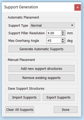
And now another entry in the “3D printer is not the solution to everything” file.

I’ve had ambitions to build my own delta robot ever since I watched an YouTube video of ABB FlexPicker industrial robots at work. Key part of the robot geometry is a set of parallel links and I thought I’d try printing my own.

The reason why I thought this exercise might be interesting is that 3D printer offers the unique possibility of printing objects in place. This means the socket can be designed purely to hold the ball in place, without any provision for the ball to be inserted or removed because there’s no assembly.

Drawing the test piece up in OnShape was fairly straightforward. A few prints were required to dial in the precise gap needed between the ball and socket so they print as tight to each other as possible without fusing together. Once that was figured out, I had a set of parallel links that moved very poorly.

On the upside, the theory was correct. The ball was printed inside the socket and was held tightly. It’s never coming out, because it never had to be inserted in the first place.

On the downside, 3D printers can’t (yet) print very smooth surfaces. Which resulted in rough movement as the printed layers moved past each other. Far inferior to standard polished metal joints, except maybe when they have sand and dirt inside.

img_20161026_175726
Close up of ball joint, showing the printed layers that give it a rough surface.

Ah well, it was worth a try. If I want to build my delta robot, I will go buy some mass-produced ball-and-socket joints that’ll be much smoother than anything I can print with the 3D printer I have. Small projects can use joints from the remote-control hobby world, big projects can draw from the McMaster-Carr catalog.

Simplify3D

simplify3d_logo_rUp until this point I used Cura 2.x, which met all of my STL to G-code slicing needs. But the caliper battery tray project demanded more.

I needed to print supports for the battery tray project components because the shape could not be laid flat on the print bed. Cura, like all decent slicer software, could generate supports. However, the Cura-generated supports are a take-it-or-leave-it affair: There is no way to edit the support structure. This is a problem when the structure ends up in an inconvenient place that is dimensional critical and difficult to clean up. Such was the case for one of the fastener holes.

After a few failed attempts due to inconveniently located support structures, I looked for a solution online. The common answer seems to be to leave Cura behind and switch to Simplify3D, so I did. I immediately dove into the part that motivated the purchase: editing supports.

s3dsupports
When tearing your hair out, the Manual Placement feature alone makes it worth the $150 price.

I was very happy to see it worked as advertised! I was able to add and remove supports as needed to make sure I got support where I needed, and avoided supports where the shape is critical and I couldn’t afford to have support material in there.

Another benefit of Simplify3D is the G-code visualization component. Cura had rudimentary visualization but I was never happy with it. My workaround had been to upload the .gcode file to http://gcode.ws for visualization, but going to yet another web site was a huge hassle in my workflow.

Sadly, Simplify3D was not all win. The print rafts generated by Cura worked out much better for my printer than the rafts generated by Simplify3D. Fiddling with raft parameters were to no avail: Cura rafts were much more helpful and peeled off cleaner than those from Simplify3D.

You win some, you lose some, such is the story of an evolving field like 3D printing.

Caliper Battery

caliper-batteryI had been using an inexpensive digital caliper to take measurements feeding into my Onshape CAD projects. It has proved sufficiently precise for my hobbyist level work but I’d definitely recommend paying for higher quality caliper for professional level work.

One annoying aspect of this caliper is that pushing the on/off button doesn’t really turn it on/off. It’s more akin to on/standby, where the display turns off but some part of the electronics are still on. This is clearly visible by turning the caliper “off” then moving the caliper – it detects the movement and displays comes back to life showing the new reading, which is impossible if the device actually turned off.

The consequence of this feature is that the device is constantly draining the little LR44 battery, which lasts only a few weeks no matter how little the caliper is used.

I decided to solve this problem with a bigger battery. I had set my eyes on the AA battery, which has significantly more capacity and far less expensive than a LR44. When the dimensions didn’t work out, I downsized to AAA battery size.

I didn’t want to make any permanent changes to the original caliper, so no drilling, gluing, or soldering. This meant that I had to:

  1. Find an attachment point: I settled on the thumb wheel, which is held in place by a plastic hook screwed into the main assembly. My project will displace this hook, taking over the thumb wheel retention duty. This allowed a solid connection conveying movement force parallel to the axis of caliper movement. Unfortunately, it doesn’t help hold things in place perpendicular to the axis of caliper movement, which led to…
  2. Grasp the rail: The battery tray needed to grasp the rail both above and below the rail in order to remain aligned to the slide at all times.
  3. Clear the rail end: The tray necessarily reduce the travel range and thus the maximum value I could read on the caliper. An early draft reduced the usable length by the length of the battery, which was unacceptable. Redesigning the battery case reduced the loss to roughly 1cm of range.
  4. Emulate a LR44: Since I didn’t want to solder, something would have to pretend to be a LR44 battery. This took the form of a cylinder with strategically placed wires exposed to make contact with the battery terminals inside the caliper.

AAA batteries are far more plentiful and far less costly than LR44 batteries. The reduced measurement range hasn’t proven to be terribly annoying. Certainly far less annoying than replacing an expensive LR44 battery all the time!

caliper-aaa

This was the most geometrically complex shape I’ve created to date. The dimension requirements were to hold the thumb wheel in place, grasp the rail tightly enough yet still allow sliding motion, and present the cylinder pretending to be a LR44 battery. It took quite a few iterations to get all the pieces positioned relative to each other.

It was also too complex of a shape to be printed directly on the flat bed of a 3D printer. All of my previous projects avoided any need for printed supports by creative positioning, but I couldn’t circumvent the need this time. The support requirements were complex and the automated support generation in Cura proved insufficient. I needed a way to adjust the support to fit the requirements of the project and the capabilities of my specific 3D printer.

Eventually I gave up on Cura and switched to Simplify3D as my slicing software, mostly for the ability to customize the generated supports.

That’s a story for another post.

Cardboard VR Tapper

utopia-tap
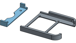
And now, a story of failure not the fault of the 3D printer. The previous project allowed my Nexus 5X phone to sit correctly in the Utopia 360 VR viewer. This project addresses the next problem: the need to tap the screen during use of the VR app.

The first step is to buy a “touchscreen stylus” available everywhere (marginally useful) electronics accessories are sold. I planned to design and 3D print a small contraption to put inside the headset to hold the stylus and press it against the screen on demand.

The holder part was a tube whose dimension needed to match the stylus so it can be held tightly. That took a few trials and errors. Then the problem is how to mount it and how to control it from outside the viewer. After a failed design using rotation motion and a small spring, I switched to a linear motion design with a rubber band.

The rubber band’s role is to keep the stylus at a particular location. Then I can use a length of string to pull the stylus away from that position, against the screen. Once tension is released from the string, the rubber band will pull the stylus back to standby position.

img_5110
Touchscreen stylus widget inside the VR viewer.

Mechanically, this screen tapper contraption worked – I could pull the screen and the stylus would push against the screen, but nothing happened!

After a bit of research, I learned that the stylus is not enough to trigger the capacitive touchscreen by itself. To trigger the necessary capacitance effects, the stylus needed to be in electrical contact with a person’s finger, so it only works when held by hand, not when held by a plastic rubber band widget.

Darn.

At this point I got frustrated with the whole thing and didn’t feel like designing a new V3 tapper mechanism. I went even lower tech – drill a hole so I can hold the stylus by hand and tap the screen from outside the viewer.

Sometimes, the solution doesn’t involve a 3D printer.

img_5111
Ultra low-tech solution: Drill a hole for the stylus. Now it can be manipulated from outside the viewer and tap the screen inside the viewer.


Nexus 5X in Utopia 360 (Google Cardboard VR)

5x-in-utopiaEarlier this week Google officially released details about their upcoming Daydream VR. And we know what that means – massive discounts on the old Google Cardboard VR headsets!

Google Cardboard was launched with some fanfare two years ago. But with impending Daydream VR they are old news and retailers are clearing their inventory. I picked up one example of the breed, Utopia 360, as a Deal of the Day from Best Buy. This viewer allowed the lenses to adjust both for distance between eye and distance to screen. Much better than the fixed-lenses devices like the Mattel View-Master VR.

There are a few problems with the Utopia 360, though. The first I tackled was the phone mount mechanism. It was a sprint-loaded set of plastic clamps that has the unfortunate property of pressing and holding down the power button on the Nexus 5X, turning the phone off. Another mounting solution will be needed.

Since I had measured the dimensions of my Nexus 5X for the car holder project, the data easily translated into a project to make a replacement phone mount. The Utopia 360 bracket had to be two pieces as the phone mount area is too large for my little 3D printer to print all in one piece.

Since I’m customizing to a specific phone, there’s no need for sprint-loaded adjustability. The bracket precisely fits and grasps a Nexus 5X, with a cutout to stay clear of the power and volume buttons on the side. The end is also open, so I can plug in headphones and power if I needed to. And a little final touch: circular cutout to clear the phone’s camera bump, allowing the phone to sit flush.

img_5109
Utopia 360 VR viewer with new custom mounting bracket for Nexus 5X

Now I can enjoy Google Cardboard VR experiences on my Nexus 5X in the Utopia 360 viewer without being rudely interrupted by the phone powering off or changing the sound volume. I am, however, unable to interact with the VR app. While more recent Cardboard VR viewers like the View-Master included a lever for the user to tap the screen, Utopia 360 did not.

That’ll be the next project.


3D Printer, Fix Thyself.

fan-adapter
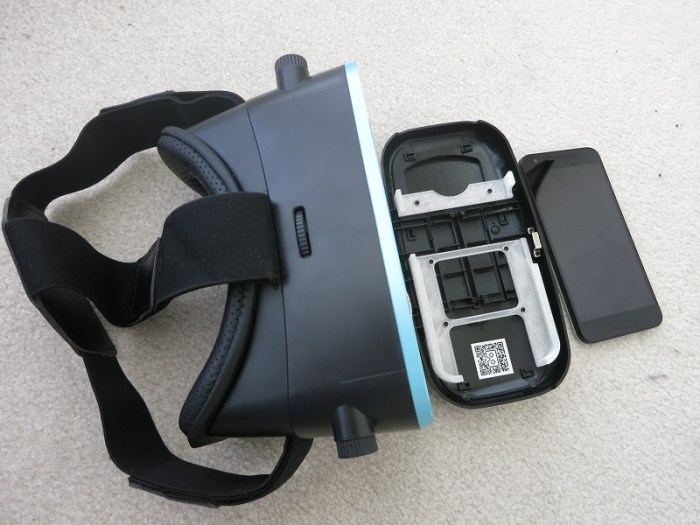
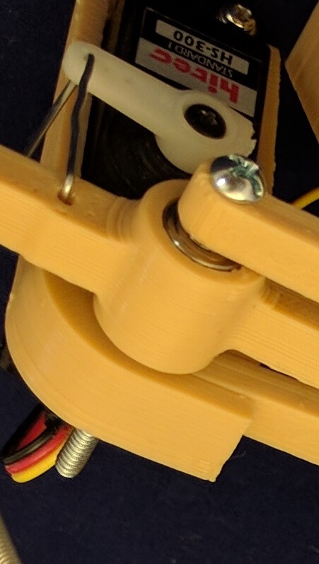
I’ve enjoyed using my 3D printer to solve little problems around the house. This project was extra amusing: I wanted to solve a problem I had with my 3D printer that I wanted to solve with the 3D printer.

My Monoprice Select Mini 3D Printer is a basic unit built to a low cost, and I’m probably using it a lot more than it was designed for. The first component to show serious wear was the tiny 30mm cooling fan, a simple unit with a cheap sleeve bearing that wore out. As a result the fan started vibrating and making quite a racket.

I could easily buy a direct replacement fan online, but where’s the fun in that? I have a 40mm fan just lying around anyway. Let’s make an adapter!

For a while I was stymied by the fact that the two fans were mounted in opposite and inconvenient directions. The original 30mm fan screws were pointed in the direction of airflow, and the original 40mm fan screws were pointed against the airflow. This meant that when one set of fasteners were mounted on an adapter, holes for the other set would be blocked.

I spent approximately an hour tearing my hair out trying to design something clever, to no avail. Then clumsiness came to the rescue: I held the cooling duct (which the fan would be mounted on) in my hand, trying to think, when I accidentally dropped it. When it hit the floor, it fell apart into two pieces.

The duct was actually two pieces fit snugly against each other. All this time I had thought it was a single piece! With the two pieces apart, the interior of the duct became accessible. This meant I could use the 30mm fan screws opposite of the original direction (pointed against the airflow) where it is no longer blocked by the 40mm fan.

Suddenly the adapter project became trivial.

“Oops” moment for the win!

Nexus 5X holder for Mazda RX-8

nexus-5x-holder
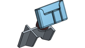
Given how popular it is to have mapping and navigation on the phone, there are a lot of phone mount products on the market. Unfortunately, given the diversity of phones and of cars, it isn’t feasible for product manufacturers to custom make individual design for every car + phone combination, so every mount is a generalized trade-off of some sort.

Which is, of course, the ideal situation for a 3D printer. Making an unique product to solve an unique problem. In my specific case, I wanted to mount a Nexus 5X phone in my Mazda RX-8 vehicle. This was the result.

The base of the phone slides in to the holder, and fortunately its position and basic friction is enough to hold the phone in place. I didn’t have to add any kind of clasp or snap to hold the phone in place.

The two slots in the base are for the two cables I wish to plug into the phone. The center slot is made to precisely fit a Monoprice USB-C cable. The side slot is made to precisely fit the plug of the Kensington audio cable I am using, one with ground loop isolation.

I didn’t want to do anything permanent to the car such as drilling holes for mounting. So I shaped the base to fit in the ashtray. I originally intended to print a large block so it fills the whole ashtray cavity but changed my mind when I realized the extra space is useful for coiling up the extra length of cable and make things tidier. Using the ashtray had the bonus side effect of placing it adjacent to the cigarette lighter power socket.

The entire design is too large for my little 3D printer to print all at once, so it has been divided up into three parts that can each be printed without support.

  1. The ashtray insert
  2. The phone holder
  3. A cylinder to connect them, one face truncated at the appropriate angle to hold the phone for display.

I printed this design in ABS plastic because of its higher melting temperature. The interior of a car gets hot and I wasn’t sure if 3D-printed plastic would melt in the heat. Printing in ABS also had the additional benefit of letting me use acetone as glue, melting the ABS pieces together results in a very strong bond.

holder

Spotting Scope Webcam Adapter

scope-adapterSpotting scopes sold for bird watchers and rifle marksmen can be quite inexpensive compared to serious camera lenses of similar zoom capability. I knew there was a difference in the picture quality but wanted to try it first hand.

Since the picture is zoomed in so far, any physical movement is greatly magnified in the image. Which meant simply holding the webcam up against the eyepiece by hand just resulted in many blurry pictures. Taping them to each other wasn’t good enough – the small movement allowed by tape was enough to distort the picture. What I needed was a solid adapter to hold them against each other.

3D printer to the rescue!

The scope eyepiece unscrews easily, which makes for a convenient mounting point for a 3D printed bracket. The webcam is then attached to the bracket by means of a ring matching the diameter of the webcam. I didn’t want to spend too much time on fancy fastening designs on the first draft, intending to use tape. As it turned out friction was enough to hold everything together well enough for a quick experiment.

scope-camera

Results of the experiment: you get what you paid for. The image quality of a cheap webcam looking through a cheap scope was barely legible. I don’t intend to put more money into this investigation, so I’m unlikely to upgrade to better scopes. What I do have, though, are some better cameras which might be worth experimenting down the line.

One problem that I should have foreseen was the very incompatible fields of view of the two instruments. A webcam is designed to capture a very wide field of view, because during video chats the face is very close to the webcam. A spotting scope is just the opposite – it has a narrow field of view of a very distant object. When I put them together, what I get is the narrow scope view in the middle of a big wide field of black.

backyard-cat
A stray cat resting in the backyard under a leafy bush against a yellow brick wall.


Flan jar lid

flan-jar-lidNowadays people are familiar with recycling. But some people forget recycling is only the third alternative in “reduce, reuse, recycle.” The goal of this project is to reuse small glass jars instead of tossing them into glass recycle.

The jars came from an eight-pack of flan in little single-serve portions. The jars were sealed with a layer of foil, which was sufficient to preserve the flan until the expiration date, but the foil top was not reusable.

In order to reuse these jars, I need to make some lids. At first I thought a simple revolve would do the job – draw the profile of a lid with a lip, revolve it 360 degrees, done! Sadly it wasn’t that easy.

Problem #1: neither ABS nor PLA were flexible enough to make a practical lid. What I had drawn up is the shape of a Tupperware lid but my material did not have the flexibility of Tupperware lids. I thought this was solvable by making the lid precise enough so that it only needed a tiny bit of flexibility to work. That’s when I ran into the next problem…

Problem #2: The flan jars were not perfectly round and varied from jar to jar. This was perfectly acceptable for their original usage of sealing with a foil top, but tremendously inconvenient for me! It’s not practical to try to match the precise shape of each individual jar just to make a lid.

To work around these  problems, I switched the design so that the lid slides on to the jar sideways. Half the lid is rigid, reinforced by a strong lip to hold on to the jar. The other half has a small lip at the far end keeping the lid in place. The lack of a strong lip gives the lid a tiny bit of flexibility, so the small lip can be bent out of the way and the lid can slide off the jar.

The lids make the jars useful for holding small tools and parts.

flan-jar-lid