The first attempt at a delta robot has come and gone, a fun experience with valuable lessons. This design used a central spine that locates the axis for each of the three arms. The servos were mounted to a bracket that was in turn mounted to the spine. The arms themselves were mounted on bearings then mounted on the spine. A long machine screw holds the arms and the servo brackets together.
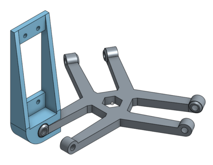
The main motivation behind this design is to isolate the servo motor from load bearing duties. The load on the arm goes to the bearings, which then go directly to the spine. The servo is only responsible for the movement.
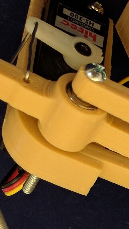
The linkage from servo horn to arm, combined with the servo mount bracket to spine connection, added significant play to the entire assembly. It is possible to move the arm freely across around 10 degrees of range. I decided this was unacceptably poor accuracy to trade off against bearing the load, which turned out to be very light and not a concern like I feared.
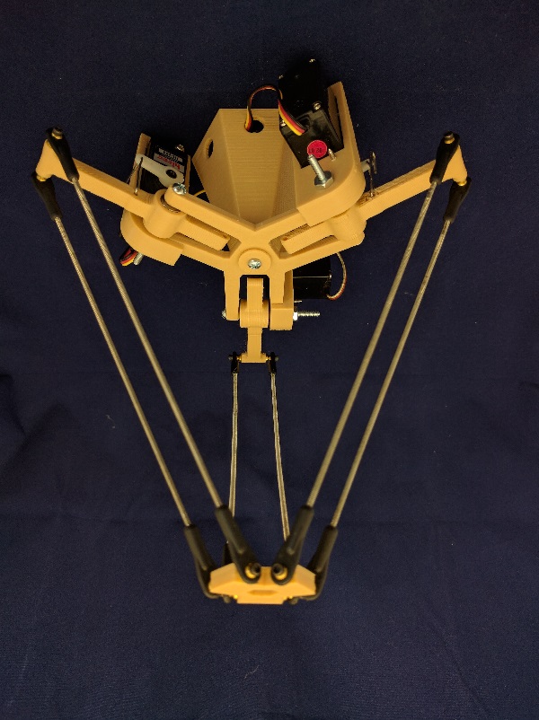
Each of the arms also featured a mounting point for a counterweight. The idea is to balance out the mass of the workload, but everything was light enough that the servos can easily keep things in place without counterweight assistance. The arm for the counterweight took away from the length of the working arm, which reduced the working volume of the robot assembly. So that wasn’t a good trade off, either.
It was an easy decision to scrap this version and move on. I’ll try again with a different design incorporating lessons from the first draft.
