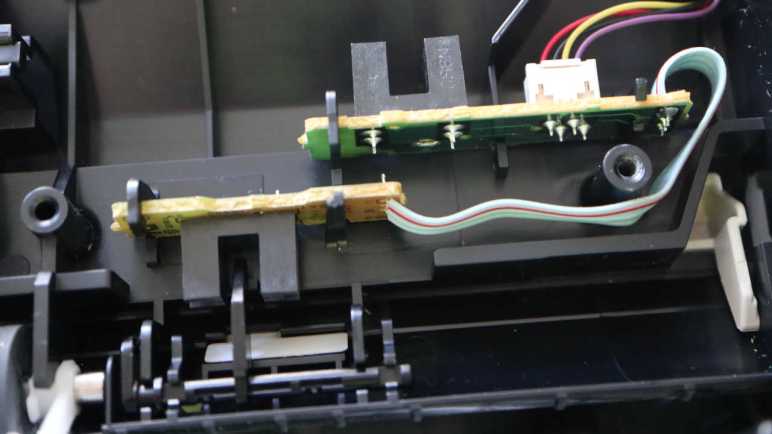
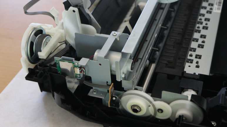
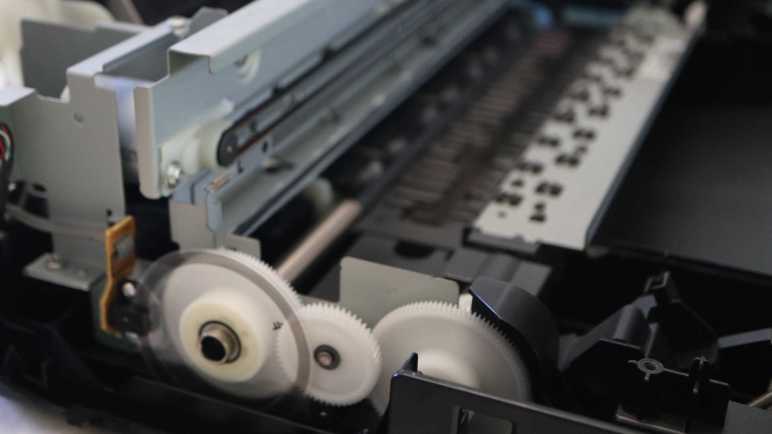
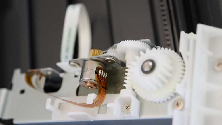
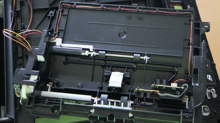
When I pulled the scanner image sensor bar from a partially disassembled Canon MX340 multi-function inkjet, I didn’t expect to understand very much of it. However, I was able to figure out the LED illumination subset of the scan head! Encouraged by this success, I felt more positive about trying to tackle the rest of the sensor bar. Which meant investing time to do a little bit of research.
When I set out to probe the electrical behavior of MX340 components, I did a brief search and found this type of sensor is called a contact image sensor (CIS). When searching for information online, getting the name is a big part of the battle. The Wikipedia page is sadly just a stub, and I don’t have the knowledge to expand it myself. (Yet?) The only source cited on that page is a ten year old link now dead, so I have to find something else.
When looking for information on electronics components at a hobbyist accessible level, I found it’s useful to search for the component and “Arduino”. Using that keyword distinguishes product sales pages from electronics details. Sadly I found nothing more helpful than the Arduino forum page that taught me the name. Searching for the name by itself found a lot of eBay listings selling replacement parts, which isn’t useful for my goal of learning about the sensors.
Scrolling through search results, my attention was caught by a link to the CIS section on Canon Components web site for businesses. This sounds like the current-day counterpart to the dead source link on Wikipedia. It is a page advertising Canon’s engineering prowess and aimed at companies that may build products around Canon CIS units. So the page exists to encourage these companies to contact the Canon sales team, which isn’t me.
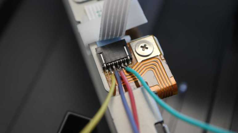
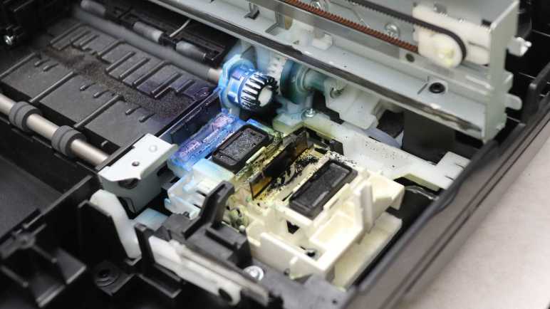
Still, the page was informative. There’s a diagram breaking down the major components of Canon CIS technology, so I can get an idea of what parts I’m looking at and their names. Before seeing this diagram, I had thought the imaging sensor sits somewhere behind the clear optical lens. Now I know the clear optical lens is merely the light guide for the LED emitters I had just examined. The sensors actually look through a linear lens array adjacent to the light guide.

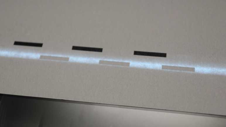
Armed with this knowledge, I went back to look at the sensor bar and found the row of small lenses that I had never noticed before. They are tiny, each lens is roughly 0.3mm across. As a rough approximation, that’s roughly 75 of them in an inch (~25.4mm). Scanners usually advertise their resolution as 300dpi or some multiple thereof (1200dpi, etc.) which means each of these lenses must correspond to more than one pixel in the resulting scan data. That process involves optical imaging magic out of scope of my current project: learn how they work electrically.
Clicking on the link for “Contact Image Sensor Product List” brought me to a sample selection of current Canon CIS products. I was most interested in the “Output form” column, specifying broadly how the sensor outputs its data. Possibilities include LVDS, which I have little hope of reading. Camera Link is also listed, and I had to go to Wikipedia to learn it is a protocol built on top of LVDS. And finally, there’s “analog output” which superficially seemed like the cheapest option. If I’m lucky, that’s what a cheap multi-function inkjet would have.
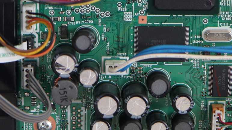
I don’t see any details on how image information is transmitted via Camera Link, LVDS, or analog. But I’ve learned a little more about contact image sensors today and maybe this is enough for me to recognize sensor image data when I see it under an oscilloscope.
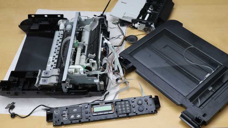
This teardown ran far longer than I originally thought it would. Click here for the starting point.