After a few wrong turns, I think I have a good grasp of the interface for talking with the audio (CD player) portion of a Honda Accord dashboard. This circuit board also includes HVAC (heating/ventilation/air conditioning) controls, though I investigated only their knobs and ignored the electronics. This page is a summary of my investigation into interfacing with audio controls.


Electrical
There are at least three independent circuits present.
- Panel backlight using small incandescent (filament) bulbs with a blue cover. Draws 0.6A at14.4V DC.
- LCD backlight draws 0.2A at 14.4V DC.
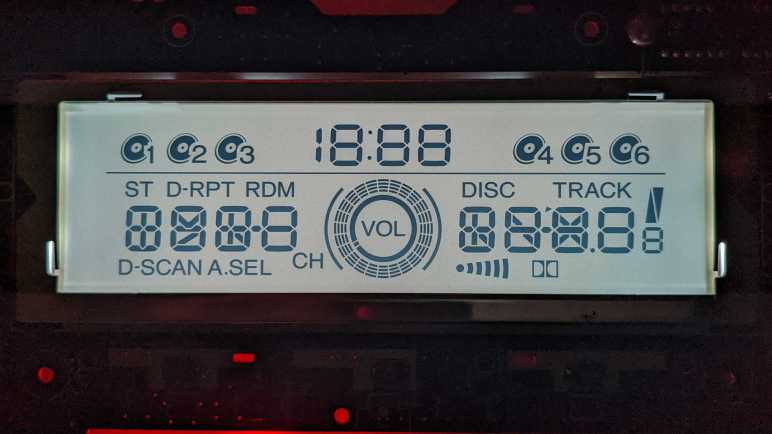
- Digital communication with Sanyo LC75883 LCD driver chip, which is a 5V part. We can send data to control LCD segment display and use it to read data for most of the button presses.
| Pin | Label | Description |
|---|---|---|
| 1 | LAMP+B | Power for panel light bulbs, up to +14.4V relative to LAMP-RET. |
| 2 | LAMP+B | Power for panel light bulbs, up to +14.4V relative to LAMP-RET. |
| 3 | LAMP-RET | Return for panel light bulbs. |
| 4 | LAMP-RET | Return for panel light bulbs. |
| 5 | LCDLAMP+B | Power for LCD backlight, up to +14.4V relative to LCDLAMP-RET. |
| 6 | LCDLAMP-RET | Return for LCD backlight. |
| 7 | P-GND | Ground. |
| 8 | P-GND | Ground. |
| 9 | P-GND | Ground. |
| 10 | IS BUS FRAME | Unknown. |
| 11 | IS BUS DATA | Unknown. |
| 12 | CD-LED | Unknown. |
| 13 | IGN-DET | Unknown. (Ignition Detect?) |
| 14 | SWD-VDD | +5V power supply for LC75883. |
| 15 | D-GND | (Digital?) ground. |
| 16 | LCD-DI | Data in from LC75883 chip. (Wired to LC75883 DO pin.) |
| 17 | LCD-DO | Data out to LC75883 chip. (Wired to LC75883 DI pin.) |
| 18 | LCD-CLK | LC75883 Clock. |
| 19 | LCD-RST | LC75883 Resets when pulled to 0V. Pull to 5V for normal operation, do not leave floating. |
| 20 | LCD-CE | LC75883 Chip Enable. |
| 21 | ENC VOL-DN | One of two quadrature encoder phases for central audio control knob. |
| 22 | ENC VOL-UP | One of two quadrature encoder phases for central audio control knob. |
| 23 | EJECT | Normally open, shorts to ground when “Eject” button is pressed. |
| 24 | PW SW | Normally open, shorts to ground when “Power” button is pressed. |
Digital
All control for LCD segment and key scanning for most of the buttons are handled by a Sanyo LC75883 chip. It communicates with a Sany proprietary protocol called CCB (Computer Control Bus) that has some resemblance to I2C or SPI but is neither. It listens on address 0x42 for bits indicating which LCD segments should be active, and reports on address 0x43 indicating which buttons were pressed. I have an Arduino sketch (target device: AVR ATmega328P based Arduino Nano) that demonstrates how to interact with the LC75883. Pressing the “Mode” button will cycle between the basic “turn all segments on” program, a bit pattern “drawing” program, and an animated demo.
This Arduino sketch for this investigation is publicly available on GitHub.
