HP Split X2 (13-r010dx): Docking Base Internals

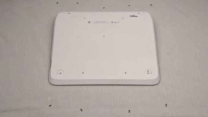
After I’ve poked around in the main tablet unit of this convertible laptop, attention shifted to the docking base. There were 9 screws, 4 of which were hidden under rubber feet which had to be removed.

HP Split X2 13-r010dx base

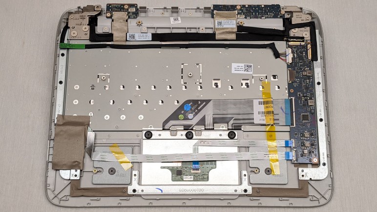
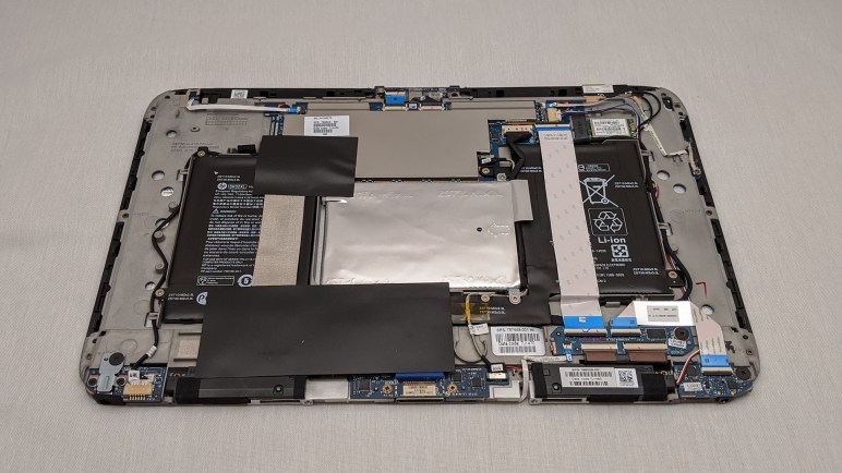
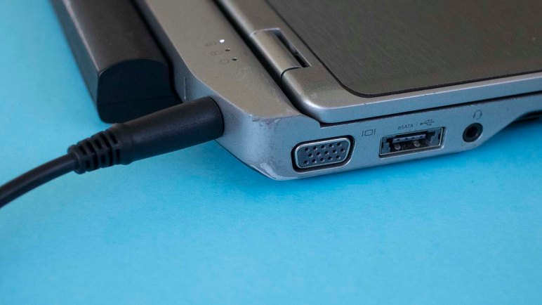
Once the screws were removed, only a few tabs held the panel in place. Since the base had functionality in addition to just hosting a keyboard and touchpad, it was not a surprise to find circuit boards near the USB ports, HDMI port, and SD card reader. But there is also a long, much larger than expected, circuit board. This base must be more sophisticated than what I gave it credit for.

HP Split X2 13-r010dx base unused connector

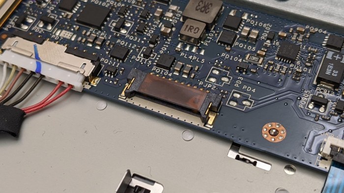
An unused connector caught my attention. Typically when a connector is not used, it is not even soldered to the board. (See earlier examination of a potential M.2 connector.) This connector is soldered, but unused. Perhaps supporting a feature of an upscale model or an optional upgrade, but I have no guesses on what it might be.

HP Split X2 13-r010dx base possible ballast

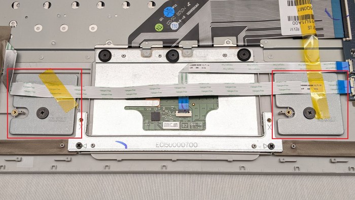
Another unusual point of interest are these two pieces of metal flanking the touch pad. They appear to serve no electrical or structural purpose, and I speculate they are here just to provide a few grams of weight. Convertible tablets like this device are top-heavy and it’s a challenge to prevent them from toppling over backwards when open. Clever geometry could solve most of this problem, but when all else fails, bolt some counterweight to the base far from the hinge for leverage. Some laptop shoppers compare by weight, motivating companies to go to great lengths to reduce overall weight. Adding counterweights negates the effort, so I would guess these were done as a last resort.

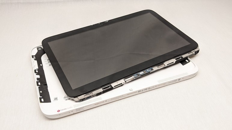
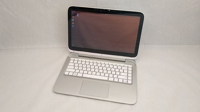
There was more inside this base than I had expected. Now that I’ve looked around the insides, it’s time to put this machine back together and write down some concluding thoughts before moving on.

HP Split X2 (13-r010dx): Tablet Innards

I took apart this convertible tablet/laptop with the goal of upgrading a SATA hybrid drive to a full SSD, but I was foiled. Since I had it open anyway, I took a look around. With the hybrid drive sitting directly in the middle and batteries on either side, circuit boards were necessarily scattered on either side with ribbon cables connecting them.

Most of the computing brains resided on a circuit board up top, and peripheral interfaces lived on the bottom. Including the microSD slot, headphone jack, charging port, and the docking connector. In between them were black speaker assemblies, one left and one right.

HP Split X2 13-r010dx wifi module

There were also provisions for interface cards to flank left and right of the main processing board. On one side is a WiFi interface module, with wires leading to antennae. The antenna is smaller than I had expected, but I don’t know enough to say if this necessarily meant reduced WiFi range. I also noticed the WiFi module didn’t occupy the entire width of the interface slot, leaving a few pins unconnected. I don’t think I’ve ever seen that before.

HP Split X2 13-r010dx unpopulated connector

The opposite side is even more interesting, with pads for an absent connector. This has roughly the pin counts to be a M.2 “B key” edge connector which could support a M.2 SSD. There’s also a hole cast into the chassis that’s roughly the correct distance to secure a M.2 2280 card. But like my previous experience with unpopulated connectors, several adjacent supporting components also seem to be missing from the circuit board so I am not confident I can just solder a M.2 connector and make things go.

I was curious if the 4GB RAM on this board could be upgraded. If a standard memory module is here it would be under the metal shield covering most of the processing board, but I didn’t want to dig that deep just yet. 4GB is enough to cover basic tasks and it is clearly not designed to be easily upgraded.

[UPDATE: I dug deeper and didn’t find memory modules.]

With curiosity about the tablet internals satisfied for the moment, I reassembled the tablet module and turned my attention to the docking base.

HP Split X2 (13-r010dx): SATA But Not As I Know It

I got this retired laptop up and running, but it felt sluggish and I thought I should try upgrading the SATA hybrid drive to a full SSD, which meant it was time to bring out the screwdriver set and dig in. When the tablet module is removed from its docking base, we can see four circles for the screws holding the tablet together. Unfastening those four screws allowed me to travel around the perimeter to pop clips loose all around the shell, allowing me to extract the heart of the machine. Flipping it face down, we see the hard drive is in the center flanked by battery modules on either side.

HP Split X2 13-r010dx tablet internals

Quite a few black adhesive-backed sheets help keep things from rattling loose. I had to peel several back to access the drive, which was itself in a foil package that I couldn’t figure out how to remove without damage. I ended up tearing the whole foil off to expose the hard drive and its data connector. I immediately realized I had a problem.

HP Split X2 13-r010dx unexpected SATA connector

I’ve never seen this kind of drive connector before. This machine’s spec sheet called it a SATA drive, but it is apparently not the same kind of SATA drive I’ve dealt with to date. Certainly the SATA SSD I had planned to install into this machine would not fit, seeing how it has an entirely different (and much larger) connector.

HP Split X2 13-r010dx will not take SATA drive on hand

Removing the original drive, its label identifies itself as a WD Black Solid State Hybrid Drive. 500 GB capacity with 8GB NAND Model WD5000M21K. A search indicates this connector is called SFF-8784. (*) Adapters are available (*) to put one of these drives in a SATA slot type I’m familiar with, which looks to be only possible because of its compact dimensions. And because of those dimensions, the reverse is not possible: we can’t put the popular form factor SATA drive into a space designed for SFF-8784. However, there exist adapters (*) to put a mSATA drive into such a location, or adaptor for a M.2 form factor SATA drive (*).

I own a few M.2 SATA SSDs, but they are currently in active use. When I retire one it might be interesting to get a M.2 adapter to put in this machine. I’ll wait until that happens, or until an interesting project arises, before buying anything. [UPDATE: A M.2 SATA SSD became available for experimentation, and I got an adapter (actually two) to perform the upgrade.]

I have to abandon the SATA SSD upgrade project for now, but since I already have the shell open, I’m going to look around just for curiosity’s sake.


(*) Disclosure: As an Amazon Associate I earn from qualifying purchases.

HP Split X2 (13-r010dx): Up And Running

I’ve looked over exterior and spec sheet for the first of three research project laptops from NUCC. With its battery charged, I turned it on to see what we have. I was greeted with the login screen for an installation of Ubuntu 14. This was enough to verify the system boots and runs. I do not have the password, so it was time to wipe the disk and install a fresh operating system. I have a suitable USB flash drive on hand with the Ubuntu 18.04 installer.

I usually work with Dell laptops, whose typical convention is to hold down F12 while turning it on to select booting from a USB installation drive. This did not work, so I went back to HP documentation to find it is actually F9 for this laptop. Furthermore, since this keyboard is the type to make function keys pull multi duty, it appears I had to also hold down the Fn key at the same time as F9. It’s important not to lose the docking base as neither F9 upon powerup nor USB installation disk is possible with just the tablet module.

It took a few tries before system boot selector recognized the Ubuntu 18 installation USB drive. I don’t think it is random when USB drives are recognized as a boot option. But if it is not random, it was definitely following a system I did not quite understand. Still, I eventually got Ubuntu 18 installer to run successfully.

Normal everyday functionality appears to work under Ubuntu 18, surprisingly this included the portrait/landscape orientation sensor and a touch friendly on-screen keyboard. When Ubuntu abandoned Unity in version 18, I thought their ambition of a unified tablet-friendly interface also died. I now know I was wrong. But even though single-point touch worked well, multi-point touch support is lacking. One example: two finger pinch failed to zoom in/out as expected.

Which meant if I wanted consistent multi-touch support on this screen, I will need to install Windows. Touchscreen tablet/laptop convertibles like this are likely to be from the Windows 8 era, which meant it’s likely to have a Windows license key embedded in the hardware. This hypothesis was confirmed when Windows 10 build 1911 reported itself activated after an uneventful installation onto this laptop.

Both Ubuntu and Windows were more sluggish than I had expected for this machine. A look at system activity shows a lot of time waiting for disk. I guess neither OS is compact enough to fit within the 8GB NAND cache of this hybrid drive. To verify this hypothesis, I’ll try to upgrade the SATA hybrid drive to a full SATA SSD and see if it makes the system more responsive.

HP Split X2 (13-r010dx): Hardware Specifications

The first of three old laptops from NUCC to be examined stumped me at first. I found very little information printed on the device and it took a while before I realized it was a convertible tablet. All the information labels were hidden while the tablet was docked. Once I separated the pieces, I could read all the identifiers including its model number 13-r010dx. From there it was easy to find HP’s product page for this machine.

While in laptop mode, the device has a full size SD memory card slot, one HDMI port, and two USB ports. By detaching the base turning it into a tablet, we also expose a duplicate charging jack, a headphone jack, and a microSD memory card slot. I find it odd that the headphone jack is a tablet mode exclusive, and even more odd that they felt it was important to have two flash memory slots.

For robot brain purposes I would have preferred to have a physical Ethernet jack but I can do without. USB Ethernet adapters are plentiful, though the ones I’ve tried had problems with long term reliability. On the upside, both memory card slots are full depth slots so cards sits flush against exterior and would not jut out. So for example, I could keep a microSD card in the tablet and still dock it to the keyboard base without mechanical interference. For robot brain purposes, memory cards are useful for data transfer and logging.

Keyboard feel is decent and the accompanying touchpad is satisfactorily large. Sadly the screen resolution was a disappointing 1366×768. It was accompanied by tablet style features like a touchscreen and a portrait/landscape orientation sensor. None of these would be critical as a robot brain but might be pertinent for other uses.

A sticker proclaimed its processor to be a Core i3, the spec sheet elaborated it is a Core i3-4012Y that I expect to be capable but not super speedy. 4GB of RAM should be sufficient for most purposes, and storage is a SATA hybrid hard drive with 500GB of spinning magnetic platter storage backed by 8GB of NAND Flash memory cache. I don’t recall any prior experience with these hybrid drives and looking forward to seeing one in action. The charge port LED changed from orange to white indicating full charge by the time I was ready to turn it on.

HP Split X2 (13-r010dx): Charge and Split

I came home from Sparklecon 2020 with several laptops that had been awaiting reuse at NUCC. I took on the research project to determine the best way to put them to work. My primary goal was to turn them into robot brains, but I will need to keep my mind and eyes open for the best use. All three machines had depleted batteries, so I had no idea of their current condition.

I started with the bulkiest machine of the bunch, primarily because I could start charging its batteries with a Targus universal laptop AC adapter I already had on hand along with the H2 tip that seemed to fit charging jack dimensions. When I plugged it in, I saw an orange LED illuminate on the laptop and we were in business. The other two laptops appear to take Targus type I tip, currently on order via the “Tips from Targus” program and I’ll examine them after the adapter arrives and I could power them.

While I waited for some power to be put back into this flat battery, I wiped down the machine with a disinfectant wipe and examined the machine as I did so. I was surprised at the sparse text at the bottom of the machine. I would have expected to find a model number, FCC ID, the usual identifiers, but I only found a few cryptic alphanumeric designations. Fiddling with the various controls I found, I pushed a slider and the machine came apart in my hands. I panicked for a second before realizing this was supposed to happen.

HP Split X2 13-r010dx tablet

This machine is a tablet/laptop convertible, and the screen could detach from its base. The bottom of the screen, previously blocked by the keyboard base, is where all the product identification information were. Now I can get started researching this device.

Dell Latitude E6230: Working Too Well To Be Dismembered, NUCC to the Rescue

The previous few blog posts about my refurbished Dell Latitude E6230 was written several months ago and had sat waiting for a long-term verdict. After several months of use I’m now comfortable proclaiming it to be a very nice little laptop. Small, lightweight, good battery life, and decently high performance when I need it. (At the cost of battery life when doing so, naturally.)

The heart of this machine is a third generation Intel Core i5, which covers the majority of computing needs I’ve had while away from my desk. From the basics like 64-bit software capability to its ability to speed itself up to tackle bigger workloads. When working away from a wall plug and running on battery, the E6230 slows only minimally. Unlike my much newer Inspiron 7577 which slows drastically while on battery to the extent that it occasionally felt slower than the E6230. I can run my 7577 for perhaps two to four hours on battery, never far from a reminder of its limited on-battery performance. Whereas I can run the E6230 for around four to six hours on battery, without feeling constrained by reduced performance.

The E6230 has several other features I felt would be good for a robot brain. Top of the list is an Ethernet port for reliable communication in crowded RF environments. Several “SuperSpeed” USB 3 ports are useful for interfacing with hardware. And when I want more screen real estate than the built-in screen can offer, I have my choice of VGA or HDMI video output.

That built-in screen, with its minimal 1366×768 resolution, is about the only thing standing between this machine and greatness. Originally I did not care, because I had planned to tear the case apart and embed just the motherboard in a robot. But this laptop is working too darned well to be subjected to that fate! For the near future I plan to continue using the E6230 as a small laptop for computing on-the-go, and kept my eyes open for other old laptops as robot brain candidates.

An opportunity arose at Sparklecon 2020, when I mentioned this project idea to NUCC. They had a cabinet of laptops retired for one reason or another. I was asked: “What do you need?” and I said the ideal candidate would be a laptop with a broken screen and/or damaged keyboard, and have at least a Core i3 processor.

We didn’t find my ideal candidate, but I did get to bring home three machines for investigation. Each representing a single criteria: one with a busted screen, one with a busted keyboard, and one with a Core i3 processor.

Close enough! And now it’s time for me to get to work on a research project: determine what condition these machines are in, and how they can be best put to use.

Dell Latitude E6230: Blank ExpressCard Placeholder Is Also A Ruler

I found a fun little design while looking over the refurbished laptop I had bought. It was a Dell Latitude E6230, which had an ExpressCard slot. I’ve never used a laptop in a way that required add-on hardware. No PCMCIA, no ExpressCard, etc. Few of my laptops even had provisions for an expansion slot. But I remembered one of them — an old Dell XPS M1330 — included a little bit of creativity. Rather than the typical blank piece of plastic placeholder, the expansion slot held an infrared remote control with simple media buttons like “Play”, “Pause”, etc. This lets people use the little laptop as a media player where they can sit back away from the keyboard and still be able to control playback.

This laptop is from Dell’s business-oriented Latitude line, so it would not be keeping with product position to have such entertainment-oriented accessories. But I was curious if it had more than just a blank piece of plastic placeholder. So even though I had no ExpressCard to install, I popped out the blank to take a look. I was happy to see that someone put some thought into the design: the blank plate is a small ruler with both inch and millimeter measurements.

This feature cost them very little to implement, and it would never be the make-or-break deciding factor when choosing the laptop, but it was a fun touch.

Dell Latitude E6230: Soft Touch Plastic Did Not Age Well

When I looked over the exterior of my refurbished Dell Latitude E6230 laptop, I noticed  some common touch parts of the wrist rest and touch pad had been covered with stickers. They were very well done on my example. It took me a while to realized they were even there. In use, they were not bothersome.

Initially I thought they were there to cover up signs of wear and tear on this refurbished machine, but I’ve realized there’s an additional and possibly more important reason for the sticker: The plastic material for the wrist rest has degraded.

Usually when plastic degrades it hardens or discolors, but for certain types of plastic, the breakdown results in a sticky surface that is unpleasant to touch. I usually see this in the flexible plastic shroud for old cables and not in rigid installations like a keyboard wrist rest. I assume these machines were originally built with some type of soft touch plastic which degraded in this very unpleasant manner.

I wonder what the production story behind this laptop is. I can think of a few possibilities right away and I’m sure there are more:

  1. Dell did not perform long term testing on this material and didn’t know it would degrade this way.
  2. Dell performed testing, but the methodology for accelerated aging didn’t trigger this behavior, so it didn’t show up in the tests.
  3. Dell was aware of this behavior, believed it would not occur until well after warranty period, and thus not their problem.

The expensive way to solve this problem would be to re-cast the plastic wrist rest in a different material and replace the part. Covering just the important surfaces with stickers is an ingeniously inexpensive workaround. Once the stickers were installed, I wouldn’t have to touch the unpleasant surfaces in normal use. However, there are still some sections exposed around the keyboard, and the sticky material is now a dust magnet.

It is a flaw in this little capable machine, but one I can tolerate thanks to the stickers. It made the laptop cheap to buy refurbished, and I’ll be less reluctant to take the computer apart and embed it in a robot, which is one of the long term plans for this machine.

Dell Latitude E6230: Hardware Internals

I picked up a Core i5-powered Dell Latitude E6230. It was a refurbished item at Fry’s Electronics, on sale for $149, and that was too tempting of a bargain to pass up. There were two major downsides to the machine: a low resolution 1366×768 display that I couldn’t do anything about, and a spinning magnetic platter hard drive that I intend to upgrade.

As is typical of Dell, a service manual is available online and I consulted it before purchasing to verify this chassis use standard laptop form factor SATA drive for storage. (Unlike the last compact Dell I bought.) Once I got it home, it was easy to work on this machine designed to be easily serviceable as is most Latitudes. A single screw releases the back cover, and the HDD was held down by two more screws. With only three screws and two plastic modules to deal with, this SSD upgrade needed less than five minutes to complete.

But since I had it open anyway, I spent some more time looking around inside to see signs of this laptop’s prior life.

Dell Latitude E6230 interior debris

There were a few curious pieces of debris inside. A piece of tape that presumably held down a segment of wire has come loose, and the adhesive is not sticky. This is consistent with aged tape. There was also a loose piece of clear plastic next to the tape. I removed both.

The CPU fan had an fine layer of insignificant dust clinging to its surface. I would have expected an old laptop to have picked up more dirt than this. Either the buildup has been cleaned up (and the cleaner ignored the tape and clear plastic) or more likely this laptop spent most of its time in an office HVAC environment with well maintained dust filtration.

The HDD that I removed was advertised to have a copy of Windows 10. But where is the license? Computers of this vintage may have their Windows license embedded in hardware. Though this is less likely for business line machines, as some businesses have their own site license for Windows. I installed Windows 10 on the SSD and checked its licensing state: not activated. The Windows 10 license is on that HDD and not in hardware. That’s fine, I intended to run Ubuntu on this one anyway, so I installed Ubuntu 18.04 over the non-activated Windows 10.

Once Ubuntu 18.04 was up and running, this machine proved quite capable. All features appear to be usable under Ubuntu and it is easily faster than my Inspiron 11 3180 across the board. It is a bit heavier, but much of that is the extended battery and might be worth the tradeoff.

Overall, a very good deal for $149 and my new ROS robot brain candidate.

Dell Latitude E6230: First Impressions

Dell’s business oriented Latitude line command a price premium over their consumer grade Inspiron offerings, some of that money actually does go towards features for long term durability of those machines. A Latitude X1 I bought over a decade ago is still running. None of the Inspiron I’ve purchased has lasted nearly as long.

But despite their longevity, many businesses retire their computers on a regular schedule independent of actual condition. Once retired they go into a secondary market, a great opportunity for bargain hunters. Recently a batch of refurbished Dell Latitude E6230 were on sale for $149 at Fry’s Electronics and that was too good of a deal to pass up. For comparison, a new eighth-generation Core i5 processor is roughly $200 at retail, and that’s just the processor. This refurbished machine has an old but still capable third-generation Core i5 processor at its heart, and an entire computer around it including storage, memory, display, and battery. The price/performance ratio here trounces every other candidate for a ROS robot brain. Even the low cost leader, the Raspberry Pi, would have a hard time matching this price point after adding storage, display, battery, etc. In terms of computing power, an old Core i5 will have no problem leaving a Raspberry Pi in the dust.

I’ve had good luck with refurbished Dell computers so far. (Including that teenager Latitude X1.) So I thought I would pick up one of these units to see what I had to trade off for this screaming bargain. The answer is: not a whole lot.

The machine is very definitely used. There are visible wear and tear on exterior, but all purely cosmetic: discoloration of emblems, rubbed off paint, things along those lines.

Dell Latitude E6230 palm rest sticker

A typical sign of wear on an old laptop is the palm rest. I saw no wear at all in the palm rest area and was impressed until I realized what they had done: They’ve added a sticker over the palm rest to give it a new surface. The curled-up visible edge of this sheet gave the trick away. The surface of the touchpad, another frequent sign of age, also received the sticker treatment.

According to the documentation in its box, this laptop’s refurbishment was performed by a company called Advanced Skyline Technology, Ltd. Side effect of a non-Dell refurbished computer are a few tradeoffs for cost. The AC power adapter is not a genuine Dell item, neither is the battery. However, the battery has the larger size of an extended runtime battery. If it actually offers longer runtime that would be a pleasant surprise.

This machine came with a spinning platter hard disk, which I was not interested in using so the first project with this machine is to open it up, look around its insides, and upgrade it to a solid state drive.

VGA Signal Generation with PIC Feasible

Trying to turn a flawed computer monitor into an adjustable color lighting panel, I started investigating ways to generate a VGA signal. I’ve experimented with Arduino and tried to build a Teensy solution, without success so far. If I wanted full white maybe augmented by a fixed set of patterns, Emily suggested the solution of getting a VGA monitor tester.

They are available really cheaply on Amazon. (*) And even cheaper on eBay. If I just wanted full white this would be easy, fast, and cheap. But I am enchanted with the idea of adjustable color, and I also want to learn, so this whole concept is going to stay on the project to-do list somewhere. Probably not the top, but I wanted to do a bit more research before I set it aside.

One thing Emily and I noticed was that when we zoomed in on some of these VGA monitor testers, we can tell they are built around a PIC microcontroller. My first thought was “How can they do that? a PIC doesn’t have enough memory for a frame buffer.” But then i remembered that these test patterns don’t need a full frame buffer, and furthermore, neither do I for my needs. This is why I thought I could chop out the DMA code in the Teensy uVGA library to make it run on a LC, keeping only the HSYNC & VSYNC signal generation.

But if I can get the same kind of thing on a PIC, that might be even simpler. Looking up VGA timing signal requirements, I found that the official source is a specification called Generalized Timing Formula (GTF) which is available from the Video Electronics Standards Association (VESA) for $350 USD.

I didn’t want to spend that kind of money, so I turned to less official sources. I found a web site dedicated to VGA microcontroller projects and it has tables listing timing for popular VGA resolutions. I thought I should focus first on the lowest common denominator, 640×480 @ 60Hz.

The PIC16F18345 I’ve been playing with has an internal oscillator that can be configured to run at up to 32 MHz. This translates to 0.03125 microseconds per clock, which should be capable of meeting timing requirements for 640×480.

I thought about leaving the PIC out of the color signal generation entirely, have a separate circuit generate the RGB values constantly. But I learned this would confuse some computer monitors who try not to lose data. So we need to pull RGB values down to zero (black) when not actively transmitting screen data. It would be more complex than just focusing on HSYNC/VSYNC but not a deal breaker.

[UPDATE: I continued this project with an ESP32.]


(*) Disclosure: As an Amazon Associate I earn from qualifying purchases.

VGA Investigation Continues with Teensy

After deciding the Arduino VGAX library was not going to serve my needs, I started researching other ways to generate a VGA signal. What became clear pretty quickly was that a standard Arduino isn’t fast enough to meet timing requirements without additional hardware support. So solutions that work entirely in software will be roughly as limited as VGAX, and those that work for higher resolutions require auxiliary hardware.

Given that fact, I started looking at VGA signal generation by a faster line of microcontrollers: the Teensy line. I have on hand a Teensy LC and a Teensy 4, and I found this thread on Teensy forums announcing a library for generating VGA signal strictly in software, no auxiliary hardware. Browsing through the Github repository of this uVGA library, it looked quite promising. However, the primary target platform is the Teensy 3. I bracket it above and below with a Teensy 4 and a Teensy LC. Would one of them be able to run this code?

An attempt to compile an uVGA example for the Teensy LC failed:

In file included from /home/roger/Arduino/libraries/uVGA/examples/HelloWorldColour/HelloWorldColour.ino:3:0:
/home/roger/Arduino/libraries/uVGA/uVGA.h:297:16: error: 'TCD_t' in 'class DMABaseClass' does not name a type
DMABaseClass::TCD_t *edma_TCD; // address of eDMA TCD registers

My best guess is that the Teensy LC lacks the direct memory access (DMA) capability uVGA requires. I’ve already been foiled once on the reduced hardware capability on a Teensy LC, so this was no surprise. DMA is critical for shuttling memory back and forth without bogging down the CPU for timing-critical tasks (like VGA signal generation) so this requirement is unlikely to be lifted.

However, since my goal is only to generate a signal outputting a single color to the entire screen, I don’t really need to shuttle data from a video frame buffer for display. If I’m willing to dig into the uVGA code, I can probably find a way to bypass the commands moving memory and accomplish my very specific goal.

Before I start doing work, though, I should see what happens when I try compiling the same uVGA example for the Teensy 4:

In file included from /home/roger/Arduino/libraries/uVGA/examples/HelloWorldColour/HelloWorldColour.ino:8:0:
/home/roger/Arduino/libraries/uVGA/uVGA_valid_settings.h:59:17: note: #pragma message: No resolution defined for this CPU frequency. Known CPU frequency: 240Mhz, 192MHz, 180Mhz, 168Mhz, 144Mhz, 96Mhz, 72Mhz, 48Mhz

It looks like the uVGA library has some hard-coded dependencies on a Teensy CPU’s frequency, and it doesn’t know what to do with the high speed of a Teensy 4. I expect that speed will open up new capabilities, but someone has to teach uVGA about a Teensy 4 before that could happen. If I’m willing to dig into uVGA code, this would be a more productive and forward-looking way to go and a positive contribution to the open source community.

But before I can realistically contemplate that project, I’ll need to become a lot more knowledgeable about VGA timing requirements.

Sparklecon 2020 Day 2: Arduino VGAX

Unlike the first day of Sparklecon 2020, I had no obligations on the second day so I was a lot more relaxed and took advantage of the opportunity to chat and socialize with others. I brought Sawppy back for day two and the cute little rover made more friends. I hope that even if they don’t decide to build their own rover, Sawppy’s new friends might pass along information to someone who would.

I also brought some stuff to tinker at the facilities made available by NUCC. Give me a table, a power strip, and WiFi and I can get a lot of work done. And having projects in progress is always a great icebreaker for fellow hardware hackers to come up and ask what I’m doing.

Last night I was surprised to learn that one of the lighting panels at NUCC is actually the backlight of an old computer LCD monitor. The LCD is gone, leaving the brilliant white background illuminating part of the room. That motivated me to dust off the giant 30-inch monitor I had with a bizarre failure mode making it useless as a computer monitor. I wasn’t quite willing to modify it destructively just yet, but I did want to explore the idea of using the monitor as a lighting panel. Preserving the LCD layer, I can illuminate things selectively without overly worrying about the pixel accuracy problems that made it useless as a monitor.

The next decision was the hardest: what hardware platform to use? I brought two flavors of Arduino Nano, two flavors of Teensy, and a Raspberry Pi. There were solutions for ESP32 as well, but I didn’t bring my dev board. I decided to start at the bottom of the ladder and started searching for Arduino libraries that generate VGA signals.

I found VGAX, which can pump out a very low resolution VGA signal of 160 x 80 pixels. The color capability is also constrained, limited to a few solid colors that reminded me of old PC CGA graphics. Perhaps they share similar root causes!

To connect my Arduino Nano to my monitor, I needed to sacrifice a VGA cable and cut it in half to expose its wires. Fortunately NUCC had a literal bucketful of them and I put one to use on this project. An electrical testing meter helped me find the right wires to use, and we were in business.

Arduino VGAX breadboard

The results were impressive in that a humble 8-bit microcontroller could produce color VGA signals. But they were not very useful in the fact that this particular library is not capable of generating full screen video, only part of the screen was filled. I thought I might have done something wrong, but the FAQ covered “How do I center the picture” so this was completely expected.

I would prefer to use the whole screen in my project, so my search for signal generation must continue elsewhere. But seeing VGAX up and running started gears turning in Emily’s brain. She had a few project ideas that might involved VGA. Today’s work gave a few more data points on technical feasibility, so some of those ideas might get dusted off in the near future. Stay tuned. In the meantime, I’ll continue my VGA exploration with a Teensy microcontroller.

Arduino Mozzi Wilhelm Exercise

After completing a quick Mozzi exercise, I found a few problems that I wanted to fix in round 2.

The first problem was the use of audio clip from Portal 2. While Valve Software is unlikely to pursue legal action against a hobbyist exercise project for using one short sound from their game, they indisputably own the rights to that sound. If I wanted a short code exercise as any kind of example I can point people to, I should avoid using copyrighted work. Hunting around for a sound that would be recognizably popular but less unencumbered by copyright restrictions, I settled on the famous stock sound effect known as the Wilhelm scream. Information about this effect — as well as the sound clip itself — is found all over, making it a much better candidate.

The second problem was audible noise even when not playing sampled audio. Reading through Mozzi sound code and under-the-hood diagram I don’t understand why this noise is coming through. I explicitly wrote code to emit zero when there’s no sound, which I thought meant silence, but something else was happening that I don’t understand yet.

As a workaround, I will call stopMozzi() when playback ends, and when the button is pressed, I’ll call startMozzi(). The upside is that the noise between playback disappears, the downside is that I now have two very loud pops, one each at the start and end of playback. If connected to a powerful audio amplifier, this sudden impulse can destroy speakers. But I’ll be using it with a small battery-powered amplifier chip, so the destruction might not be as immediate. I would prefer to have neither the noise nor the pop, but until I figure out how, I would have to choose one of them. The decision today is for quick pops rather than ongoing noise.

This improved Arduino Mozzi exercise is publicly available on Github.

Arduino Mozzi Space Core Exercise

Temporarily stymied in my Teensy adventures, I dropped back to Arduino for a Mozzi exercise. I’ve helped Emily through bits and pieces of putting sampled audio on an Arduino using Mozzi, but I had yet to run through the whole process myself.

The hardware side was kept as simple as possible: there’s only a single switch wired to be normally open and momentarily closed. For audio output, I used the wire salvaged from the Project MC2 Pixel Purse(*) that was briefly a hacker darling due to its clearance-sale price. (As of this writing, the price is up to $39.58, far above the $6 – $8 leading to its “buy to take it apart” fame.) Since this cable was designed to be plugged into a cell phone, it had a TRRS plug that I rewired into an imitation of a monophonic TS plug by using the T wire and connecting RRS together into another wire.

With hardware sorted out, I dived into the software tasks. There were more than a few annoyances that make this task not very beginner-friendly. The Huffman audio compression utility audio2huff.py had dependencies listed only in a comment block easily overlooked by beginners. They didn’t all install in the same way (purehuff required a download and install, while the others were installed via pip.) And since they are a few years old and not actively maintained, they were all written for Python 2.

This will become more and more of a problem as we go, since Python 2 support has just officially ended at the start of 2020. Older Linux distributions would launch Python 2 when the user runs python at the command line, and those that want to use Python 3 would need to run python3. This is getting flipped around and some environments now launch Python 3 when the user runs python and those that need the old stuff has to run python2.

What happens when we run these utilities under Python 3? It’d be nice if the error message is “Hey, this needs Python 2” but that’s not the reality. It is more likely to be something like “foobar is not iterable” completely bewildering to beginners.

To be fair, none of these are problems specific to Mozzi, there’s a large body of work online that were written for Python 2 and waiting for someone motivated enough to bring them up to date.

Anyway, after those problems are sorted out, I got my Arduino to play a sound when the button is pressed. My test sound clip was from the game Portal 2: the ecstatic “SPAAACE!” emitted by the corrupted Space Core when it finally got its wish to go flying through space.

This Arduino Mozzi exercise is publicly available on Github.

[UPDATE]: “Wilhelm” exercise (round 2) has some improvements.


(*) Disclosure: As an Amazon Associate I earn from qualifying purchases. But you shouldn’t buy a Pixel Purse until it drops back down to clearance prices.

First Experiment in Teensy Audio Foiled By CPU Instruction Set

The original line of Arduino boards are know for a lot of very flexible features that made them the champion of entry into physical computing. “Large storage space” is not one of those features, as the ATmega328P has only 32KB of flash. Plenty for blinking little LEDs and a great many other projects, severely limiting for anything that requires nontrivial amount of data.

One such class of projects is playing back digital audio samples. Simple sounds like tones, beeps, and bloops take little data, but recorded digital audio consumes a great many bytes. I was introduced to the Mozzi Arduino sound synthesis library via exposure to Emily’s projects. While the emphasis is on synthesis, it does have provision to handle sampled audio. However, due to the small flash storage, even with compression it could only handle short sounds.

Looking around for an upgrade, I remembered I have a Teensy LC OSH Park edition I had purchased alongside an OSH Park order years ago and thought it was worth an audio playback experiment. The CPU is much faster and it has almost double the flash storage. Exploring the Arduino-compatibility layer called Teensyduino, I see it offers a full analog audio API, complete with a graphical tool to help compose the tree of audio input/processing/output nodes. I was very impressed!

I decided to start small with just two nodes: sound is to be generated by playing from sampled audio data in memory, and sent to built-in DAC. Pressing “Export” generated the following boilerplate code:

#include <Audio.h>
#include <Wire.h>
#include <SPI.h>
#include <SD.h>
#include <SerialFlash.h>

// GUItool: begin automatically generated code
AudioPlayMemory playMem1; //xy=262,658
AudioOutputAnalog dac1; //xy=436,657
AudioConnection patchCord1(playMem1, dac1);
// GUItool: end automatically generated code

void setup() {
// put your setup code here, to run once:

}

void loop() {
// put your main code here, to run repeatedly:

}

Sadly, this code did not compile. Instead, I encountered this error:

/tmp/ccLBGUGU.s: Assembler messages:
/tmp/ccLBGUGU.s:291: Error: selected processor does not support `smull r0,ip,r3,r5' in Thumb mode
/tmp/ccLBGUGU.s:292: Error: shifts in CMP/MOV instructions are only supported in unified syntax -- `mov ip,ip,asl r6'
/tmp/ccLBGUGU.s:293: Error: unshifted register required -- `orr r0,ip,r0,lsr r7'

A web search on this error message indicated this is because the chip on Teensy LC does not support the instructions described in the error message, I’d need a Teensy 3 or 4. To test this hypothesis, I changed the compiler to target Teensy 3 instead of LC and hit “Verify” again. This time, it was successful. But I don’t have a Teensy 3 on hand, so I can’t actually run that code.

Given this limitation I’ll have to find some other project for my Teensy LC. In the meantime, I’ll drop back to the tried and true Arduino for my Mozzi exercise.

Examining Composite Video Signal Generated By Microcontrollers

There was a several-years-long period of my life when I spent money to build a home theater. This was sometime after DVD became popular, because the motivation was my realization of how much superior DVD picture quality was over VHS. With movies on VHS, noisy visual artifacts were a limitation of the analog magnetic medium. With movies on DVD, the media-imposed limitations were gone and now there are all these other limitations I could remove by spending money, lots of it, to do things like upgrade from composite video to S-Video connections.

Eventually home theater moved to all digital HDMI, and I stopped spending big money because even the cheapest flat panels could completely eliminate classic CRT problems like color convergence. (My personal peeve.) I thought I have left the era of CRT and composite video behind, but throwing out my pile of analog interconnects and video equipment turned out to be premature.

Now I’ve found an interest in old school video again, because they are accessible for the electronics hobbyist. It is much easier to build something to output a composite video signal rather than HDMI. Local fellow maker and tinkerer Emily likes the old school tech for aesthetics reasons in addition to accessibility. So one day we got together at one of our regular SGVTech meets to dig a little deeper into this world.

Emily brought an old portable TV with composite video input, and two candidate Arduino sketches each purporting to generate composite video. (arduino-tvout and one other whose name I can’t remember now.) I brought my ESP32 dev module running Bitluni’s composite video demo. For reference Emily had an actual composite video camera, the composite video Wikipedia page and the reference document used by Bitluni for his demo.

All three were able to get the little TV to show a picture. However, they looked very different under the oscilloscope. The [name will be filled in once I remember] sketch had the wildest waveform whose oscilloscope trace didn’t look anything like a composite video signal, but the proof is in the fact an animated 3D vector graphic cube showed up on the TV anyway. The waveform generated by arduino-tvout was a little rougher than expected, but unlike the previous, it was clearly recognizable as a composite video waveform on the oscilloscope and accepted by the TV. Waveform generated by Bitluni is the best fit with we expected to see, and matched most closely with output generated by the composite video camera.

Knowledge from tonight’s investigation will inform several of our project candidates.


Optical Drive Carriage, The Sequel

During my learning and exploration of stepper motor control, I managed to destroy an optical carriage I salvaged from a laptop drive. In order to continue experimentation I need another stepper motor linear actuator of some kind. I rummaged in my pile of parts and came up empty-handed, but I am fortunate to have another local resource: Emily‘s pile of parts. My request was granted with an assembly that had an intact motor, drive screw, and linear carriage. The optical assembly in that carriage had been torn apart, but that is irrelevant for the purposes of this project.

Unlike the previous two stepper motors I played with, this one has exposed pads on the flexible control cable so I tried to solder to them. Given my experience soldering fine pitched parts, I knew it’s problematic to solder one at a time: they are so close together heat from one pad will melt solder on an adjacent pad. My best bet is to set things up so all the wires are soldered at the same time.

Emily salvaged stepper motor wiringThere is slightly less solder than I would have preferred on each of these joints, but several efforts to add solder created solder bridges across pins. Requiring removal by solder sucker, which reduced the amount of solder even more. Since there was enough for electrical conductivity, I left it as is to continue my experiments.


Unrelated to stepper motors or Grbl:

While I was taking the above picture to document my work, I noticed I was being watched and took a picture of the watcher. This little beauty was surveying my workbench perched on top of a cardboard box of M3 fasteners from McMaster-Carr. The spider was only about 5mm long overall including legs. Unfortunately at the time of this shot I had set it for shallow depth of field to photograph the above solder joint. I adjusted my camera to bring more into focus, but this little one was camera shy and jumped away before I could take a better shot. Still, I’m quite pleased with my camera’s macro lens.

Spider on McMaster Carr box

Panasonic UJ-867 Optical Carriage (Briefly) Under A4988 Control

Once I extracted the optical assembly carriage of a Panasonic UJ-867 optical drive, the next step is to interface it with a Pololu A4988 driver board. And just as with the previous optical drive stepper motor, there are four visible pins indicating a bipolar motor suitable for control via A4988. However, this motor is far smaller as befitting a laptop computer component.

Panasonic UJ-867 70 stepper motor connector

The existing motor control cable actually passed through the spindle motor, meaning there were no convenient place to solder new wires on the flexible connector. So the cable was removed and new wires soldered in its place.

Panasonic UJ-867 80 stepper motor new wires

Given the fine pitch of these pins it was very difficult to avoid solder bridges. But it appeared to run standalone so I reinstalled into the carriage. Where it still ran – but was very weak. Hardly any power at all. When I tilted it up so the axis of travel is vertical, the carriage couldn’t win its fight against gravity. Since the job is only to move an optical assembly, I didn’t expect these carriages exert a great deal of force. But I’ve seen vertically mounted slot loading optical drives. I thought it should at least be able to fight against gravity.

A Dell laptop charger delivers 19.2V. I’m not sure how many volts this motor intended to run at, but 12V seemed reasonable. Then I increased current beyond the 50mA of the previous motor. Increasing both voltage and amperage seemed to help with more power, but it remained too weak to overcome gravity.

As I’m tilting the metal carriage assembly in my hand, I started noticing it was warming. Oh no! The motor! I checked the temperature with my finger, which was a mistake as it was hot enough to be painful to human skin. I shut down my test program but it was too late, the carriage never moved again.

Lessons learned: don’t get too overzealous with power and check temperature more frequently.

And if I want to continue these experiments, I’ll need another stepper motor assembly.