Why And How Of Simpler PIC Display Driver

Earlier in my outline for starting a new PIC display driver project for a vacuum fluorescent display (VFD), I mentioned one objective was to “keep the PIC side very simple and move more display-specific logic into driving code“. Let’s go into more detail on that part of the plan.

In my previous PIC display projects, the code was written for a specific multi-segment display unit as part of the overall project. This meant the source code reflected whether the LED was a common-anode or common-cathode design, it also knew about which segment represented which parts of a particular digit. This knowledge was required because I put priority on making control communication interface easy. For the temperature demo, making my display unit show “72.3F” was a matter of sending the actual UTF-8 text string “72.3F” as bytes. The PIC then parsed that string and determined which segment to illuminate.

But there’s a good chance we have several other matrix display projects in the future, and I didn’t want to invest the time to hard code intricacies of each unit into the PIC. It would be much easier to adapt and experiment if such logic was moved to a more developer-friendly environment like Python on a Raspberry Pi. In the case of the current NEC VFD under consideration, there are segments corresponding to days of the week and other function specific segments like an “On and “Off” text, “OTR”, little clock icon, etc. Most of which won’t necessarily be present on another VFD unit, why spend the time to embed such knowledge in my PIC driver?

NEC VSL0010-A VFD Annotated

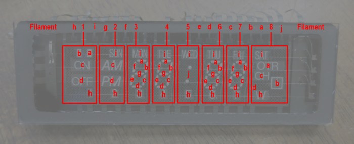
We also want the flexibility to explore using the display in ways that are far afield of its original intent. For starters, that seven-segment display in the center doesn’t have to be constrained to display numbers for a clock. All these desires meant moving away from performing data interpretation on the PIC.

Instead, the PIC will accept a raw data stream where each bit corresponds to whether a segment is on or off. Each byte will correspond to 8 segments in a grid, and so forth. This means the task of mapping a desired digit to a set of segments will be the responsibility of driver code on host device rather than PIC peripheral. PIC will only concern itself with rapidly cycling through the matrix of digits keeping them all illuminated.

Old Microchip MCC Boilerplate for MSSP Requires C90 Compatibility Mode

PIC16F18345 VFD driver PCB

I’ve figured out how to compile the new Microchip Foundation Services Library boilerplate code for implement I²C peripheral, only to learn it doesn’t do what I wanted it to do. Well darn, it’s time to go back to the tried-and-true I²C boilerplate code I’ve used in earlier projects. It’s still there, it compiles with only the “this is outdated” warning, and I knew it worked well enough to be a good starting point for my projects. It was the tried-and-true known quantity that shouldn’t give me any trouble at all.

Except it did.

The code compiled fine, but it didn’t actually work. It would give a response to the first I²C query but then it would stop responding. Here’s the default boilerplate code, which responds to address 0x08, as probed by a Raspberry Pi using i2cdetect tool.

pi@raspberry:~ $ i2cdetect -y 1
     0  1  2  3  4  5  6  7  8  9  a  b  c  d  e  f
00:          -- -- -- -- -- 08 -- -- -- -- -- -- --
10: -- -- -- -- -- -- -- -- -- -- -- -- -- -- -- --
20: -- -- -- -- -- -- -- -- -- -- -- -- -- -- -- --
30: -- -- -- -- -- -- -- -- -- -- -- -- -- -- -- --
40: -- -- -- -- -- -- -- -- -- -- -- -- -- -- -- --
50: -- -- -- -- -- -- -- -- -- -- -- -- -- -- -- --
60: -- -- -- -- -- -- -- -- -- -- -- -- -- -- -- --
70: -- -- -- -- -- -- -- --

That part looks good, the problem comes when we run the same tool again.

pi@raspberry:~ $ i2cdetect -y 1
     0  1  2  3  4  5  6  7  8  9  a  b  c  d  e  f
00:          -- -- -- -- -- -- -- -- -- -- -- -- --
10: -- -- -- -- -- -- -- -- -- -- -- -- -- -- -- --
20: -- -- -- -- -- -- -- -- -- -- -- -- -- -- -- --
30: -- -- -- -- -- -- -- -- -- -- -- -- -- -- -- --
40: -- -- -- -- -- -- -- -- -- -- -- -- -- -- -- --
50: -- -- -- -- -- -- -- -- -- -- -- -- -- -- -- --
60: -- -- -- -- -- -- -- -- -- -- -- -- -- -- -- --
70: -- -- -- -- -- -- -- --

It has disappeared from scan, as it no longer responds to I²C commands sent to its address.

Comparing the I²C boilerplate code with my old LED project, I saw no differences worth mentioning. It should be the exact same code but it no longer does the exact same thing. What has changed between my old LED project and now?

Eventually I found the answer: Microchip has updated the XC8 compiler to C99, and this compiler update causes problems with existing code. I previously saw this in the form of compiler errors on an empty MCC-generated project. I no longer see compiler errors on an empty project template but arguably this is worse: no compiler errors but silent changes in behavior.

The solution is the same as before: change project properties so XC8 compiler uses its old C90 compatible mode. Once I switched over, the I²C boilerplate code functioned as expected.

Project Properties

Since Microchip has marked this old I²C boilerplate code as deprecated, I don’t expect them to bring it up to date with the new compiler. And given its history of causing me headaches, I guess I’ll plan on using C90 mode for all my projects for the foreseeable future.

Getting Microchip Foundation Services Library I2C Boilerplate To Compile

PIC16F18345 VFD driver PCBMotivated by the desire to get an old VFD up and running for fun, I set up my PIC16F18345 to act as an I²C peripheral. I could write my own code from scratch, or I could build on top of boilerplate code published by Microchip for implementing an I²C slave device. My problem is that I had two choices – the new thing that doesn’t compile, or the old thing that is deprecated.

I’ve since figured out how to resolve the two error messages to compile the new thing, formally called Foundation Services Library.

The first compiler error message was this:

In file included from mcc_generated_files/USBI2C_app.c:25:
mcc_generated_files/drivers/i2c_slave.h:55:34: error: unknown type name 'interruptHandler'
void i2c_slave_setReadIntHandler(interruptHandler handler);
^

Searching elsewhere in the generated boilerplate, I found a declaration for interruptHandler in another different header file. Copying it into i2c_slave.h addressed the “unknown type name” error.

typedef void (*interruptHandler)(void);

However, that error was replaced by a warning that there are now duplicate declarations of interruptHandler. This seems silly – if there were a declaration to collide with, it should not have thrown an unknown type name error signifying the declaration’s absence.

MPLAB should either not throw the error, or not raise the warning, but it is doing both. I have yet to figure out if the toolchain is busted or if the boilerplate code is. For now, though, I could proceed to the next problem.

The second compiler error message was this:

mcc_generated_files/USBI2C_app.c:30:14: error: no member named 'SSP1IE' in 'PIE3bits_t'
PIE3bits.SSP1IE = 1;
~~~~~~~~ ^
1 error generated.

This one was easier to figure out – go into the header files for this chip and look for SSP1IE. I found it declared on PIE1bits instead of PIE3bits. So to get this code to compile, I changed the boilerplate code from this:

void USBI2C_Initialize(void){
PIE3bits.SSP1IE = 1;
i2c_slave_open();
}

To this:

void USBI2C_Initialize(void){
PIE1bits.SSP1IE = 1;
i2c_slave_open();
}

What does PIE1bits.SSP1IE actually do? I’m not sure so I’m not positive this is actually the correct fix. But at least all of the foundation boilerplate compiles, and I start browsing through sample code for MikroElektronika USB-I2C Click module to figure out what it does and what I can do with it. Reading through code and comments, I saw this comment block.

- This module only supports byte operations. Block read and write operations is
not yet supported by MCC Foundation I2C Slave Drivers.

This comment implies Microchip has decided to deprecate their previous I²C library even though the new library is unable to duplicate important functionality. If true, this is… unsatisfactory. I want block read and write operations for my project.

Now I’m even more motivated to stay with the old code, but unfortunately there were some complications with that, too…

I2C on PIC: Microchip Foundation Services Library Is Less Beginner-Friendly

About a year and a half ago I poked my head into the world of I²C programming with my PIC16F18345 chip. I was pleasantly surprised the MCC boilerplate code actually included an example implementation emulating an I²C EEPROM. That turned out to be a great way for me to get started.

Now that I have another PIC project in mind, I retraced my steps and saw this:

I2C driver will be removed soon

In file included from mcc_generated_files/mcc.h:55:
mcc_generated_files/i2c1.h:55:2: warning: "This version of the I2C driver will be removed soon and the correct driver to use is the Foundation Services driver" [-W#warnings]
#warning "This version of the I2C driver will be removed soon and the correct driver to use is the Foundation Services driver"

Looks like what I had used before is on its way out.

Since this is a new project, I thought I might as well check out what the new shiny object has to offer. Reading around the web, I found complaints that the previous MCC I²C code would work when conditions are ideal, but it was not very good at letting developers write code to handle error conditions. This might not be important in hobbyist projects like mine, but it was of great importance to people trying to engineer real products.

I added the Foundation Services Library module for my PIC’s MSSP. After code generation was complete, I went into the generated header files and saw a lot more functions declared than previous boilerplate code. There were a few related to overflow and bus collision errors, which I assume were there to address complaints about error handling capability.

Unfortunately, there is no longer a friendly example implementation to reference. There are a lot of declarations but no information on how to use those functions. Microchip’s claim that the Foundation Services Library code is self-documenting has been wholeheartedly laughed at by other forum users. But the forums did point me to Microchip’s  MikroElektronika Click Library which interfaces between those nifty little Click modules to a PIC using Foundation Services Library. The trick is finding one that most closely matches what I’m trying to do. Many Click modules are I²C slaves controlled by a PIC acting as master, I wanted my PIC to act as I²C slave accepting commands. A first pass through the Click library found only the USB-I2C Click module, so I installed sample code corresponding to that module and tried to build it.

unknown type name interruptHandler

In file included from mcc_generated_files/USBI2C_example.c:36:
mcc_generated_files/drivers/i2c_slave.h:54:34: error: unknown type name 'interruptHandler'
void i2c_slave_setReadIntHandler(interruptHandler handler);

Sample code that fails to compile is… not the height of beginner friendliness.

After 30 minutes of hunting around, I failed to find a solution to this problem and decided to return to the old deprecated I²C driver. It may not be the newest and shiniest thing, but it does compile and run.

Dusting off Past PIC LED Driver Projects For Potential VFD Driver

While the VFD salvaged from a VHS timer/tuner unit was designed to run on voltages unfamiliar to me, once we probed the control pinout I found it much less intimidating. The entire array can be treated as a matrix with its eight grids along one axis and ten elements along another axis. The array is only partially filled: there aren’t actually 80 elements on the VFD. A driver chip will energize one grid at a time, and energize the desired elements within that grid. After some time, the driver will move on to the next grid and its corresponding elements. When the switching happens quickly enough, our human eye sees only a completely illuminated display and would not notice that grid-to-grid cycling.

NEC VSL0010-A VFD Annotated

This general principle is identical to how I drove a LTC-4627JR 7-segment LED array in an earlier PIC project. The only real difference is that the transistors I had used earlier is only good for the +5V used by that LED array and not suitable for +30V for this VFD, but that can be addressed by substituting some switching components.

IMG_5272

In the previous project, I was interested in learning KiCAD and the process of ordering custom PCBs for a device for potential low-volume production. Many lessons were learned, most of which discouraged me from pursuing the thought further. This time around there is no fantasy of volume production, this will be an one-off project for a single salvaged VFD.

But now that I know the concept of a display matrix is generically applicable across multiple units, this time around I’m more inclined to keep the PIC side very simple and move more display-specific logic into driving logic which usually runs on a more programmer-friendly device like an Arduino or Raspberry Pi. (Or maybe even a ESP32!) So this time around I’m not going to decode ASCII characters or anything along those lines: I’m going to create a PIC driver that listens for commands over I2C specifically about cycling through and toggling pins. The idea is to avoid unnecessary PIC code churn that uselessly reinvent the wheel from one LED display to another, instead moving that to the Arduino/Pi/ESP32/etc side.

IMG_5238

Window Shopping BeagleBone Blue

Sawppy was a great ice breaker as I roamed through the expo hall of SCaLE 17x. It was certainly the right audience to appreciate such a project, even though there were few companies with products directly relevant to a hobbyist Mars rover. One notable exception, however is the BeagleBoard Foundation booth. As Sawppy drove by, the reception was: “Is that a Raspberry Pi? Yes it is. That should be a BeagleBone Blue!”

Beaglebone Blue 1600
BeagleBone Blue picture from Make.

With this prompt, I looked into BBBlue in more detail. At $80 it is significantly more expensive than a bare Raspberry Pi, but it incorporates a lot of robotics-related features that a Pi would require several HATs to reach parity.

All BeagleBoards offer a few advantages over a Raspberry Pi, which the BBBlue inherits:

  • Integrated flash storage, Pi requires a separate microSD card.
  • Onboard LEDs for diagnosis information.
  • Onboard buttons for user interaction – including a power button! It’s always personally grated me a Raspberry Pi has no graceful shutdown button.

Above and beyond standard BeagleBoards, the Blue adds:

  • A voltage regulator, which I know well is an extra component on a Pi.
  • On top of that, BBBlue can also handle charging a 2S LiPo battery! Being able to leave the battery inside a robot would be a huge convenience. And people who don’t own smart battery chargers wouldn’t need to buy one if all they do is use their battery with a BBBlue.
  • 8 PWM headers for RC-style servo motors.
  • 4 H-bridge to control 4 DC motors.
  • 4 Quadrature encoder inputs to know what those motors are up to.
  • 9-axis IMU (XYZ accelaration + XYZ rotation)
  • Barometer

Sadly, a BBBlue is not a great fit for Sawppy because it uses serial bus servos making all the hardware control features (8 PWM header, 4 motor control, 4 quadrature input) redundant. But I can definitely think of a few projects that would make good use of a BeagleBone Blue. It is promising enough for me to order one to play with.

Dell Alienware Area-51m vs. Luggable PC

On the Hackaday.io project page of my Luggable PC, I wrote the following as part of my reason for undertaking the project:

The laptop market has seen a great deal of innovation in form factors. From super thin-and-light convertible tablets to heavyweight expensive “Gamer Laptops.” The latter pushes the limits of laptop form factor towards the desktop segment.

In contrast, the PC desktop market has not seen a similar level of innovation.

It was true when I wrote it, and to the best of my knowledge it has continued to be the case. CES (Consumer Electronics Show) 2019 is underway and there are some pretty crazy gamer laptops getting launched, and I have heard nothing similar to my Luggable PC from a major computer maker.

laptops-aw-alienware-area-51m-nt-pdp-mod-heroSo what’s new in 2019? A representative of current leading edge gamer laptop is the newly launched Dell Alienware Area-51m. It is a beast of a machine pushing ten pounds, almost half the weight of my luggable. Though granted that weight includes a battery for some duration of operation away from a plug, something my luggable lacks. It’s not clear if that weight includes the AC power adapter, or possibly adapters plural since I see two power sockets in pictures. As the machine has not yet officially launched, there isn’t yet an online manual for me to go read what that’s about.

It offers impressive upgrade options for a laptop. Unlike most laptops, it uses a desktop CPU complete with a desktop motherboard processor socket. The memory and M.2 SSD are not huge surprises – they’re fairly par for the course even in mid tier laptops. What is a surprise is the separate detachable video card that can be upgraded, at least in theory. Unlike my luggable which takes standard desktop video cards, this machine takes a format I do not recognize. Ars Technica said it is the “Dell Graphics Form Factor” which I had never heard of, and found no documentation for. I share Ars skepticism in the upgrade claims. Almost ten years ago I bought a 17-inch Dell laptop with a separate video card, and I never saw an upgrade option for it.

There are many different upgrade options for the 17″ screen, but they are all 1080p displays. I found this curious – I would have expected a 4K option in this day and age. Or at least something like the 2560×1440 resolution of the monitor I used in Mark II.

And finally – that price tag! It’s an impressive piece of engineering, and obviously a low volume niche, but the starting price over $2,500 still came as a shock. While the current market prices may make more sense to buy instead of building a mid-tier computer, I could definitely build a high end luggable with specifications similar to the Alienware Area-51m for less.

I am clearly not the target demographic for this product, but it was still fun to look at.

USB-C Transition Confusion

Today’s little research adventure came courtesy of a comment on one of my earlier posts: my Dell 7577 laptop has a USB-C port. Some laptops – like the latest Apple MacBook – charge through their USB-C ports. Does that mean I can charge my Dell through its USB-C port?

Well… no. No I can’t. But it was an interesting experiment.

dell 7577 usb c charging no go

As is my usual habit, my first thought was to find if there’s any mention in the online version of my manual.  Clicking on the “Power” section had the usual information about a standard Dell AC adapter but no mention of USB-C charging. Clicking on the “Ports and Connectors” section returns a list that listed several functions for the USB-C port, but that list did not include power.

However, it was still an impressively long list! I had not realized the full extent of what a USB-C connector could do. I was first introduced to this connector with my Nexus 5X cell phone, and I was happy enough just to have a charge connector that had eliminated frustration with orientation.

usb orientation

But it’s not just convenience, USB-C tries to solve an impressive set of problems all with a single connector. The fact it can transfer data was a given due to USB legacy, and I knew it could transfer more power than older USB connectors from the aforementioned Apple MacBook. But it wasn’t until I found the Wikipedia page on Thunderbolt 3 that I realized how wide the ambition spread.

Not just low-speed data like classic USB, but there’s also the option for high speed video data in the form of DisplayPort support. And that’s not all – it can tap into a computer’s internal high speed PCI bus. This part of the spec is how some laptops could utilize external GPU enclosures. Such a wide range of capability explains why Apple decided their latest laptops need only USB-C plugs: one plug can handle all the typical laptop port duties.

But as my blog comment pointed out, there’s also the risk for customer confusion. A USB-C port might do all of these things someday, but clearly not all USB-C ports could do everything today. One marvel of our current system is that, for the most part, if a plug fits into a port then it is the right plug for the right port. Now we’re moving away from that. Sure, it’s nice the protocol negotiation allows the computer to throw up a dialog box telling me I can’t charge through my USB-C port, but would it have been better to avoid this confusion to begin with?

Maybe one day we’ll get to the point where every USB-C port can do everything, bringing us back to the “if it fits, it works” world we once had. In the meantime, there’s going to be a lot of confusion. Let’s see how the industry adopts USB-C over the next few years…

Entering the Wide World Of ESP32

Espressif Logo

As a thanks for participating in the ESP32 mesh network project by Morgan and Ben, people whose badges became nodes on the network were generously gifted the ESP32 module mounted to each of our badges. Unfortunately, I managed to damage mine before the big stage demo so sadly I didn’t put in the honest work to earn that ESP32. Still, I now have a damaged ESP32 that I can try to fix.

Before I start trying to fix it, though, I should have a better idea on how to tell if a ESP32 is up and running. The only mechanism I had before was to run the badge mesh network app and see if there’s any response, but I want to know more about how a ESP32 works in order to better tell what’s broken from what’s working. Also – since I’ve desoldered my ESP32 from the carrier board, it is not nearly as easy to test it against the badge.

I’ve read about a lot of projects built using the ESP32 on Hackaday, so I know it’s popular for and it would be cool to add it to my own project toolbox. Given its popularity, I thought it wouldn’t be a problem to find resource on the internet to get started.

I was right, and wrong. There is no shortage of information on the internet, the problem is that there’s too much information. A beginner like myself gets easily disoriented with the fire hose of data presented by ESP32.net.

Do I start with Espressif’s own “ESP-IDF” development framework?

Do I start with an Arduino-based approach to ESP32 development?

Do I start with Amazon’s tutorial for how to use an ESP32 with AWS?

How about other individual tinkerer’s adventures on their own blogs? Here’s one person’s initial report poking around an ESP32, including using an oscilloscope to see how quickly it can change output based on input. And here’s another Hello World, and there are many more blogs covering ESP32. (Soon including this one, I suspect.)

It’s going to take a while for me to get oriented, but it should be fun.

Adafruit Feather System

I received a Adafruit Hallowing in the Supercon sponsor gift bag given to attendees. While reading up about it, I came across this line that made no sense to me at the time.

OK so technically it’s more like a really tricked-out Feather than a Wing but we simply could not resist the Hallowing pun.

feather-logo

I can tell the words “Feather” and “Wing” has some meaning in this context that is different from their plain English meaning, but I didn’t know what they were talking about.

But since this is Adafruit, I knew somewhere on their site is an explanation that breaks down whats going on in detail. I just had to follow the right links to get there. My expectations were fully met – and then some – when I found this link.

So now I understand this is a counterpart to the other electronics hobbyist programming boards and their standardized expansion board form factor. Raspberry Pi foundation defines their HAT, Arduino defines their Shield, and now Adafruit gets into the game with feathers (a board with brains) and wings (accessories to add on a feather.)

Except unlike Raspberry Pi or Arduino, a feather isn’t fixed to a particular architecture, or a particular chip. As long as they operate on 3.3 volts and can communicate with the usual protocols (I2C, SPI), they can be made into a feather. Adafruit make feathers out of all the popular microcontrollers. Not just the SAM D21 at the heart of Hallowing, but also other chips of the ATmega line as well as recent darling ESP32.

Similarly, anyone is welcome to create a wing that could be attached to a feather. As long as they follow guidelines on footprint and pin assignment, it can fit right into the wings ecosystem. Something for me to keep in mind if I ever get into another KiCad project in the future – I can build it as a wing!


V-USB For Super Basic USB On AVR Chips

One of the gifts to Supercon attendees was a Sparkfun Roshamglo badge. While reading documentation on writing software for it, one detail that stood out about this Arduino-compatible board was the lack of a USB-to-serial bridge. Such a component is common on Arduino boards. The only exceptions I’m aware of are the Arduino Leonardo line using the ATmega32u4 chip which has an integrated USB module.

The ATtiny84 on the Roshamglo is far too humble of a chip to have an integrated USB functionality, so that deviation from standard Arduino caught my interest. In fact, not only does the board lack a serial-to-USB bridge, the ATtiny84 itself doesn’t even have a UART peripheral for serial communication with a serial-to-USB bridge. Now we’re missing not one but two things commonly found in Arduino-compatible boards.

What’s the magic?

vusb-teaserThe answer is something called V-USB, a software-only implementation of basic USB fundamentals. It is not a complete implementation, most notably it does not handle all the error conditions a full implementation must gracefully handle. But it does enough USB to support the Micronucleus boot loader. Which creates a very basic way to upload Arduino sketches to an ATtiny84 without an USB serial interface engine (SIE), or even a UART, on the ATtiny84 chip.

Yes, it requires its own custom device driver and upload tool, but there are instructions on how to make all that happen. The point is minimizing hardware requirements – no modification on the host computer, and minimal supporting components for the ATtiny84.

It looks like a huge hack, and even though SparkFun cautions that it is not terribly reliable and won’t work on every computer, it is still impressive what the V-USB people have done under such limits.

Mystery At Supercon: Supplyframe Cube

What’s big, orange, and a mystery? The Supplyframe cube given to Supercon attendees. It is a pretty neat physical manifestation of the Supplyframe logo. It is made of injection-molded plastic that’s been given some sort of surface finish treatment. The result is a vaguely satin feel more upscale than commodity plastic. It also comes in a nice cardboard box whose description of its contents were not sufficiently technical for the hardware hackers looking it over. Likely intentionally to give it an air of mystery.

Supplyframe Cube with Box

We see a micro USB port on the side, and a clear plastic rectangle mounted on the bottom. Also visible on the bottom are four screws, and removing them to see the insides revealed an expected circuit board behind the micro USB port. What was less expected was the wire soldered to the board, and a sheet of copper foil at the other end of the wire. What is this thing?

Supplyframe Cube interior

This being Supercon, people quickly figured out there’s a FTDI USB to serial chip behind the port, so computers see the cube as a serial port. When plugged in, the plastic rectangle at the bottom reveals its function to diffuse light from the twelve LEDs shining downwards. It’s all very pretty, but what does it do?

People were making headway figuring it out, and they got to check their answers during Voja’s scheduled talk about the 2018 Hackaday Supercon badge. Voja did say a few words about the badge, but he was clearly more interested in talking about the cube which he also designed. He switched gears to the cube around the 6:40 mark of the recorded talk.

The default firmware implements a random number generator that could store up to 2 megabytes of random bytes. The copper foil works as one half of a capacitor for transmitting data between two cubes sitting next to each other, so one cube can get an identical copy of the random bytes in another cube. Once copied, each cube could be used as one-time ciphers to encrypt up to two megabytes of data that only a person with the other cube can decrypt.

But of course, that’s just the default firmware. Voja went over what’s on the board and what else it can do. The LEDs are random (except when they all light up to signal a cube is waiting for transmit or receive) and there’s currently an accelerometer sitting unused. After the conference Voja created a Hackaday.io project for the cube and now we wait to see if people do fun things with it.

Miss At Supercon: ESP32 Mesh Network Demo

In the pre-Superconference badge hacking call to action, wireless badge communication was raised as a specific challenge laid out for attendees to tackle. One particularly ambitious effort was to build a mesh network for wireless communication using ESP32 modules mounted to the badge expansion header. The ESP32 mounting system is straightforward, it was the software that would prove to be tricky.

At the end of the weekend, Morgan and Ben got the network up and running with just over an hour to spare. They started recruiting people to join their IRC-style chat network for the final demo, and I signed up. In the test session I was able to see messages sent over the network, and send a few myself. But when it came time for the actual demo on stage, my badge was unable to connect! Fortunately they had enough other participants so my participation was not critical, but I was sad to have missed out. After the presentation (and winning a prize) the team told everyone on the network we could keep the ESP32 as a token of thanks.

After the conference I examined my ESP32 mount and found a few cracked solder joints. It looks like I had accidentally smashed my ESP32 module sometime between the test session and the presentation. Looking on the Hackaday.io project page, I found the simple schematic and tested connections using my multimeter. Several connections were indeed severed between the badge header and the mounting circuit board. I tried the easy thing first by reheating all the solder to see if they could bridge the gaps. This helped, but two lines remain faulty and were patched with wires.

After this patch, I tested with [mle_makes] ESP32-equipped badge and we could not communicate, indicating further problems with my ESP32. The next step is to desolder it from the board to see if I could use the ESP32 as a standalone module. Once the module was removed from the carrier board, I saw a problem: three of the pads had separated from the module, one of them being the EN(able) pin critical to a healthy ESP32. The other two damaged pads (IO34 and IO35) I hope I could live without.

Is this the end of the road for my gifted ESP32? I thought it was, but [mle_makes] disagrees. The next experiment is to try soldering to the trace leading to EN pad, or the via further inboard. This will be a significant challenge – that via is smaller than the tip of my soldering iron! 

Heard At Supercon: SAM D MCU from Atmel (Now Microchip)

One of the best parts of attending Hackaday Supercon is the opportunity to chat with other like-minded people and see what they find interesting. Because odds are good that I’ll find it interesting, too. A prime example this year was hearing about the SAM D series of microcontrollers developed by Atmel. It is now branded a Microchip product due to acquisition.

Since I was spending most of my time in the badge hacking area, “talking shop” usually meant talking about microcontrollers in one context or another. The heart of the Hackaday Superconference 2018 badge is a PIC32 processor, which doesn’t seem to be particularly well-regarded among the people I talked to. I personally pledge no particular allegiance to one chip over another – my philosophy is that they’re all tools with their own advantages and disadvantages. But that’s not the same opinion held by everyone, and it’s interesting to hear other opinions.

The PIC32 is a completely different architecture from the 8-bit PICs I’ve played with earlier.. PIC32 aim for a higher tier of products with higher functionality but also higher price. I had been aware of Atmel’s AVR line of chips, though I have yet to play with them firsthand. As head-to-head competitor with Microchip PIC for many years, they too have a low-end 8-bit offering and a high-end AVR32 line. I was also aware that ARM-based chips like those used in the Raspberry Pi and my cell phone occupies an even higher tier, though they could reach as low as PIC32/AVR32 tier.

I was wrong: They can actually be downsized even further than that! I did not know ARM can be so flexible until conversations at Supercon. Chips with a Cortex-M0 core can be price and feature competitive with 8-bit PICs and AVRs. One such example being the SAM D series of controllers. The lowest end SAM D10 is available from Digi-Key for roughly a dollar each. They’re not available in a breadboard-friendly DIP form factor for experimentation, but that can be mitigated by relatively inexpensive development breakout boards like the SAM D10 Xplained pictured below.

And the best part of learning this as part of a friendly Supercon crowd: When I honestly said I didn’t know about the SAM D series, I didn’t get an elitist “Oh you don’t know? You are so out of touch” response, I got an excited welcoming “Oh you don’t know? Well now you have something new and fun to explore!” This attitude makes a huge difference in community building.

ATSAMD10-XMINI
SAM D10 Xplained Mini evaluation board, available from Digi-Key


Hackaday Badge Nyan Cat Wrap Up

With just two minor bugs in Nyan Cat both centered around power management, I’m content to leave them for later (if ever.) And it’s not like I have any way to patch all the badges out there… we don’t exactly have a badge counterpart to Windows Update. I’m going to finish documenting this project and move on to the next.

The first item is to create a page on Hackaday.io about this project. I’ve had several projects where I documented in parallel on Hackaday.io and here, but Nyan Cat was a rush job and I couldn’t spare the time. That project page will focus on the Nyan Cat specifically, so for example it won’t have the blog entries about exploring hardware features of the Belgrade badge.

Nyan Cat on .io

The second item is to dip my toes in YouTube video content creation. I’m setting low expectations on my first effort. A short script was written beforehand but I still stumble over a few words and the delivery is a bit wooden. The camera is fixed and looking straight down at the badge. The biggest problem turned out to be lighting, I have not yet figured out the camera settings required to have it do a faithful translation of colors on screen. (I had the exact same problem a year ago.)

It’s not great, but the best way to get better is to learn by doing!

Hackaday Badge Nyan Cat Bugs

I had a great time at 2018 Hackaday Superconference and I think Nyan Cat was a success as part of the conference badge. I’m happy with it, even though I found two minor problems with my Nyan Cat app during the weekend.

The first problem was that it does not tell the badge it is running, which is required to prevent automatic power-down. The auto-sleep feature was added after my code was merged into master, shortly before the badges started getting flashed en masse. I knew this power saving feature was going in but I was busy with badge production. So I didn’t have the chance to add code to keep the badge from going to sleep while Nyan Cat is running. My life was filled with rows and rows of badges.

Acrylic back installation

What this means is that Nyan Cat couldn’t just keep running on a badge forever. The badge will go to sleep and need to be awakened for animation to resume.

Somewhat related to the above, there’s a problem with timer synchronization upon wake. It appears that when the badge is asleep, the main timer still advances at some rate. I believe this is a side effect of loop_badge() in badge.c. Called by timer #5 every 15 milliseconds to check the status of the power button. During this check, the main system timer (running on timer #1) clicks upwards even though the rest of the badge is asleep.

What this means is that, if the badge is running Nyan Cat when it goes into low power mode, the timer will advance even though the animation & music does not. As a result, when the badge wakes up, the loops in charge of animation and timing will frantically try to catch up. It only takes a second or two to get back in sync, but in that brief moment we get a comically distorted kitty running and singing at warp speed.

This second problem can be reproduced by:

  1. Launch Nyan Cat with ‘nya’ to see and hear dancing singing pop tart cat.
  2. Push the power button to put the badge in low power mode.
  3. Wait about 30 seconds.
  4. Push the button again to wake up the badge.
  5. See and hear cat in hyperdrive for a few seconds before slowing down to normal speed.

I might go back and fix these bugs in the future, but they’re not horrendous embarrassments (and Nyan Cat in hyperdrive is pretty hilarious) so I’m content to leave them as-is for now.

(Cross-posted to Hackaday.io)

Hackaday Badge Nyan Cat At Supercon

NyanCat Badge 1024w

In my pull request for Nyan Cat to go in the Hackaday Superconference 2018 badge, I included a way to launch it by typing ‘nya’ at the main menu. It existed mainly because I felt silly to create a pull request for a feature that was impossible to launch. This was originally intended to be a placeholder and be replaced by something else, but due to time crunch that “something else” never happened. So the final badge firmware flashed to every unit distributed to Supercon attendees had Nyan Cat launched via ‘nya’. It’s not the original intention, but also not the end of the world.

What this meant was that Nyan Cat badge app is now also an unplanned social experiment. By default only people who comb through badge firmware source code will find it. I didn’t think that would be enough, so on Friday I walked around telling people about it while the animation was playing on the badge around my neck. I think I told roughly one dozen people (some of them in groups) by the time Friday evening’s official kickoff party was done. Saturday morning at the official opening ceremony, I saw a person I didn’t recognize with Nyan Cat running on their badge. At that point I felt the knowledge seeding stage was complete, and it was time to let the word-of-mouth propagation take over.

One thing I thought was interesting: I had programmed a mute button to the app so it’s possible to play the animation without the music. Every time I told someone about Nyan Cat, I also mentioned ‘0’ would mute and ‘9’ would resume playback. However, as the weekend went on, I realized not everyone who knew about ‘nya’ knew about the mute button! It’s possible these people found out about ‘nya’ by reading the badge main menu source code (which launched the app) but not the app’s own source code (where the mute code lives.) It was also possible it got lost in the word-of-mouth propagation.

I knew there was a risk that people (including myself) would be annoyed at the music by the end of the weekend. But the sheer number of people packed in a small venue created a noisy enough environment that the music is actually a little difficult to hear over ambient noise. I didn’t encounter any complaints about it being a nuisance. Whew!


(Cross-posted to Hackaday.io)

Hackaday Badge: The Cat And The Hack

After all the work, my Nyan Cat is now running on an actual Supercon badge, running the default firmware which will be part of every 2018 Supercon badge. Woohoo!

NyanCat Badge 1024w

This specific unit of hardware actually has a minor assembly error: one of the battery trays is installed backwards. Here’s a picture of the back – both springs should be on the bottom, so both batteries have their positive end pointing up. The battery tray on the left is reversed from the way it should be.

Defective Badge Rear

The correct fix is to desolder the battery tray and solder it back on in the correct orientation. The simple hack is to jam a battery in there in the correct electrical orientation but against the tray orientation. Since this is a common mistake, the tray actually has a guard against reverse insertion. There’s a small plastic nub to prevent electrical contact if a battery is installed backwards. This nub allows the protruding positive end of AA battery to make contact, but keeps the flat negative end from making contact.

Nub Intact

Side note: When equipped with protective battery tray like this one, putting a battery in backwards is a valid way to stop battery power consumption, because it opens the circuit and no current will flow. However some people have gotten in the habit of reversing batteries to deactivate electronics with or without this nub. Without this nub, they risk cell voltage reversal and damaging the battery. It makes me wince to see it.

But back to the badge: since the correct battery orientation in this case is reverse of tray orientation, the expedient hack is to snip the nub away with some tools and insert the battery “backwards”.

It’s a hack and it works.

Nub Snipped

Hackaday Badge Nyan Cat Claws Back Final Bytes Before Wrapping Up

poptartcat320240There are just a few more touches before the finish line for getting my Nyan Cat project ready for consideration for the Hackaday Superconference 2018 badge. The final space savings came from realizing I only used two out of three voices in music playback, but my song structure carried three values so the unused voice takes up space holding zeroes. Maybe it’s only a few hundred bytes, but that’s still waste I could trim.

Once trimmed, I reviewed my code and realized I was still reading key-presses by reading the raw IO lines instead of using the existing stdio_get() API. This was a mistake made early on, when I thought it would block my animation/music until a key is pressed. Functionally speaking, neglecting to use the API not a terribly huge deal, but if I want the program to serve as example code it should do the right thing.

And finally, code comments. I want this to be something people can read through and understand how to write code for the badge in C using some techniques that are absent from other examples on the badge. This is an important part of the pitch for putting Nyan Cat on the badge – it should be educational in its construction in addition to being entertaining to launch.

After I committed the final code updates and comments, I realized I forgot to update the memory footprint listed by the flag to turn Nyan Cat on/off in a build. Final tally: 84 bytes of data memory, 8468 bytes of program memory. This is over the 8 kilobyte goal I was shooting for, but certainly a tremendous reduction from the original 30+ kilobytes.

I packaged my Nyan Cat into a pull request against the upstream depot, and it was accepted. Now my sample project will be a part of the default firmware on every Supercon badge.

(Cross-posted to Hackaday.io)

Hackaday Badge Nyan Cat Sheds A Few More Bytes

poptartcat320240I built my Nyan Cat project on the Hackaday Belgrade 2018 badge. Now there’s a slim opening for it to be part of the Hackaday Superconference 2018 badge. The key is to get Nyan Cat skinny enough to fit through that door. Most of the 512 kilobytes of program storage on the badge’s PIC32MX370F512H chip have already been spoken for, leaving only about 16 kilobytes available. I set out to take up less than half of that space. I’m now just over 10 kilobytes, I need to trim another 2+ kilobytes.

The first task is to port the code from a fork of the Belgrade repo over to a fork of the Supercon repo. During this move, Nyan Cat code also migrated from being a customized user_program.c to its own nyancat.c source file in order to leave the default user program alone for badge hackers to play with. First I verified it still worked in the new repo – overweight and all – then I got to work trimming more data.

The key insight for more savings is realizing that we now store a quarter-scale image of 80×60 pixels and scale up at rendering time. Since they are encoded (and decoded) one scanline at a time, this means no single run length of pixels can be longer than 80. Previously, 12 bits were used to store length because a 320×240 image may have a run of 320 – longer than the maximum 8-bit value of 256. Now I only need 8 bits for run length. (The color palette always had only 14 colors, so it still needed only 4 bits.)

This trims every run in the image, color index + run length, from 16 bits down to 12. This did indeed trim data down to a little over 8.5 kilobytes. But code readability took a hit as a result: the smallest convenient unit in C is in multiple of 8 bits, so working with 12 bit values involve a lot of bit manipulation to pack and unpack that data.

(Cross-posted to Hackaday.io)