My shipment of my own PICkit 3 and tube of PIC16F18345 has arrived, so it’s time to pick up where I left off with I²C control of the Lite-On LED module.
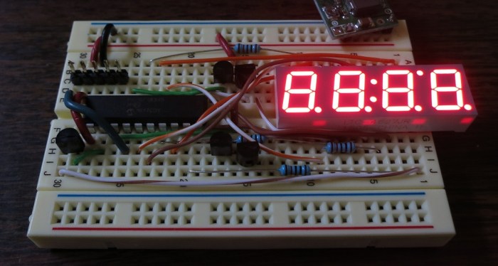
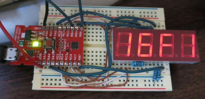
This LTC-4627JR module has a few extra enhancements over the standard 4-digit 7-segment display. The first is the addition of a period with each digit, so we can display decimal points in our numbers. The period is an additional segment to make it an 8-segment display.
In addition to the periods on each digit, there are three additional LEDs. Two are in the middle of the display making it possible to use this in a clock, as they’re positioned to show the colon in the ubiquitous blinking “12:00”. The third and final additional LED is towards the upper-right of the display. It’s not immediately clear what that would be good for, but since its siblings are clock-friendly, perhaps it can indicate AM/PM with the help of bezel markings. Electrically, these three LEDs are wired in parallel with 3 of the 8 segments of the other digits and enabled with a common anode in parallel with the 4 digits. Together the three additional LEDs are effectively a partial fifth digit on the display.
Effectively, I’m now trying to control a 5-digit, 8-segment display. A few days ago I tried to control it with a PIC16F1847, but that is an 18-pin chip so I didn’t have enough pins to drive the eighth segment or the fifth digit. Now that I have my 20-pin chip, I can wire up my breadboard with:
- 2 pins for power, +5V and Ground.
- 8 pins for the cathodes of the 8 segments, via 120 Ohm resistor to keep the current below 25 mA.
- 5 pins for the common anodes of the 5 digits, via 2N2222 transistor to control the (up to) 200mA current.
- 2 pins for I²C communication, one data and one clock.
- 3 pins for the PICkit 3 to program the chip, Vpp, ICSPCLK and ICSPDAT.
Using all 20 pins with nothing wasted.
I know that the Vpp, ICSPCLK and ICSPDAT pins can serve double-duty under restricted circumstances, but I don’t yet have a good grasp on when it’s OK to do that. For now I’m going to leave them alone for exclusive use of the programmer until I have a better grasp.
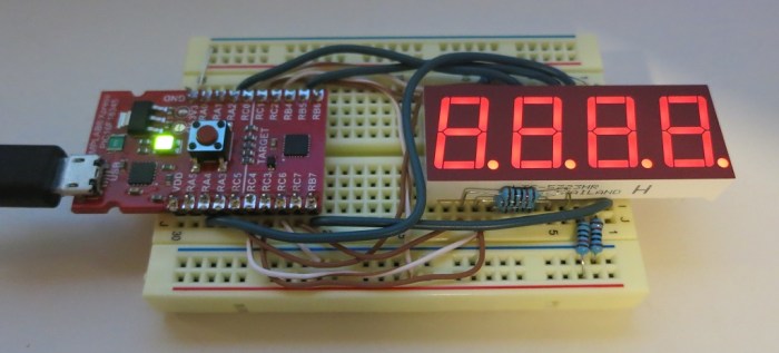
On a final note: even though I’m driving one more transistor and one more digit than before, the board still ended up cleaner and less tangled with wires. Practice makes perfect I guess.
To establish a baseline of functionality, I hooked it up to a Raspberry Pi to confirm I could talk to the Microchip boilerplate generated I²C code. And I wrote a small program to confirm I could light up all the LEDs. It looks good, we can proceed.


 Now that I have a rudimentary I²C implementation up and running on my PIC, it’s time to figure out how I’ll control it from code running on a Raspberry Pi. Which means it’s time for this novice to go bumping around in the dark looking for a place to start.
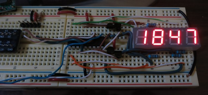

 It’s been about two weeks since I started learning the
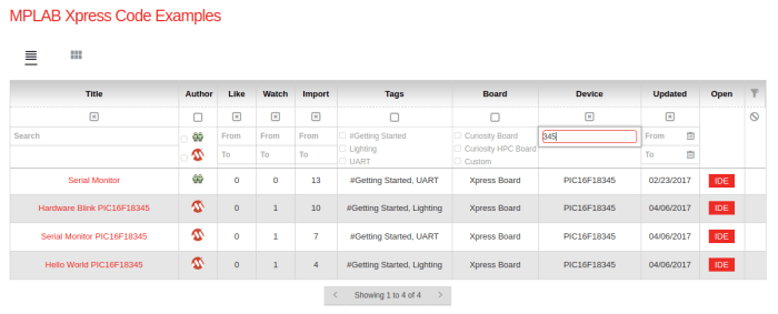
 The tutorial jumps straight into the practice with 12 simple PIC projects, each demonstrating a basic PIC task. Each project starts with how to set up hardware bits (LEDs, resistors, etc) on a project breadboard. Then it moves to the software side by walking the reader through using MCC to create all the boilerplate code setting up the project. After MCC took care of all the repetitious tasks, the reader has to add a few lines of task-specific code to finish things up.