Taylor Food Thermometer LCD First Round Fail

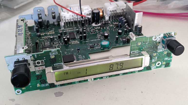
When I salvaged LCD for play later, I didn’t know enough about them to make sure I salvaged them with known controllers in working condition. Fortunately, by sheer luck I managed to do that with a car audio head unit. But this adventure started with a talk on direct control of simple LCDs and I wanted to get back to that initial motivation. My most recent LCD salvage was from a Taylor food thermometer, but it didn’t look easy to work with. Due to the fact its electrical contact is in the form of elastomeric “zebra strip” and I didn’t want to build my own circuit board to make contact with it.

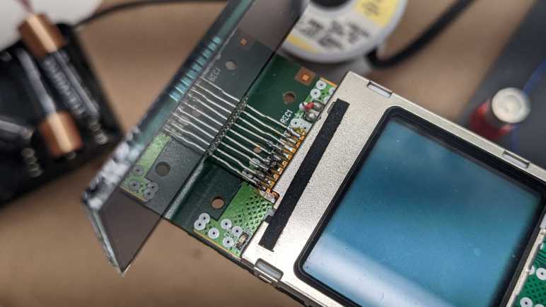
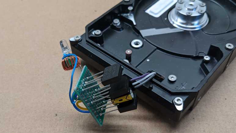
I saved the original circuit board thinking that I could use it as reference when I get around to making my own board. These are just flat rectangles of copper, each one millimeter wide and spaced one millimeter apart. Thanks to Joey Castillo’s Remoticon talk, I learned that bare LCD require very little current so I think the surface area of these contact patches are generous. Perhaps I could get away with using only part of it?

I started soldering wires to these pads, trying to keep my soldered area to less than 25% of the surface area leaving remainder clear for the elastomeric strip.

I then severed all of the original traces to make sure my experimental signals won’t route through the original chip.

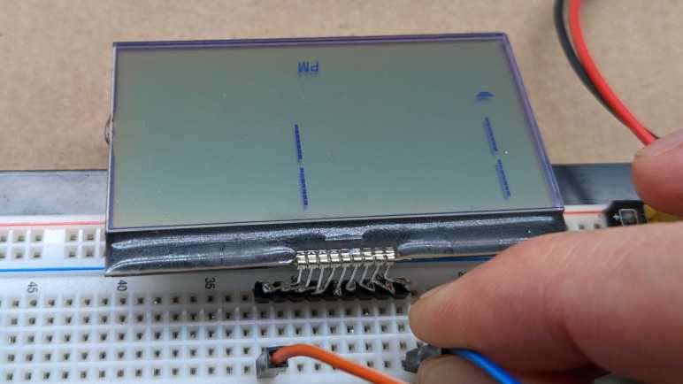
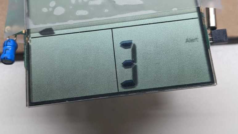
I started probing with alternating signals from an ESP8266 at 3.3V. This is what I see when I put them on the left-most and right-most wires: five segments darken, but one more clearly than the rest. “But wait, I see more than five segments” explanation: the three horizontal lines on that 3 are actually all a single segment, apparently this digit only needs to show a subset of numbers. For example, 2, 3, 5, 6, 8, and 9 can be shown with all three horizontal lines active, and 1 can be shown with all three inactive. There are four other dark segments but they are blurry. A horizontal segment in the upper left, two of the vertical segments on that digit, and a fixed text “Alert”.

Further probing found that the left-most five lines and the right-most five lines multiplex against each other, together letting me control 25 segments. Whenever I light one up, four others are blurry. After some experimentation I understand this is due to my voltage too high. Adding a voltage dividing resistor ladder (1 kilo-ohm and 470 ohm) brought it down to 2-ish Volts. Once at that level, individual segments activate cleanly without crosstalk activation of their multiplexing neighbors.

When I tried to get a picture of a single cleanly activated segment, I failed because a wire popped loose. Since this experiment required that I solder these wires to tiny fraction of the pad, these were very bad solder joints with small contact area. They began to fail one by one. Some would pop off cleanly so I knew it failed, others would seem to be physically connected but electrically discontinuous.

I got far enough to determine the multiplex scheme is different from the “common”/”segment” split mentioned in the Remoticon talk and common in multiple other LCD controllers. [Update: I was wrong. See link to update at the bottom of this post.] Figuring out the novel multiplex scheme might be interesting, but not while fighting bad electrical connections at the same time. After a few rounds of “multiplex or bad connection?” guessing game, I got frustrated and decided to postpone this puzzle until I can create better contact with the elastomeric zebra strip. I went looking elsewhere for a simple LCD.


UPDATE: I took another swing at this task and was successful on the second try.

Powering Up Toyota Audio Head Unit (86120-08010)

It appears two of my salvaged LCDs might have come from the same product, with identical (or nearly so) interface and command protocol. That is great, but I don’t know what that protocol actually is. It isn’t terribly promising as a starting point, so I decided to continue looking in my pile of salvaged electronics. Next candidate is the LCD embedded in the control panel of an automotive audio head unit. This was a stock tape deck from a 1998 Toyota Camry LE, which was replaced by an aftermarket deck for modern conveniences like Bluetooth audio. It was one of the retired pieces of equipment I brought to the January 2020 session of Disassembly Academy and taken apart. All metal pieces went into recycle, all plastic pieces went to landfill, and I kept the electronic circuit boards.

Since the metal external panels are gone, I no longer have the model number. Searching through eBay listings, I guess it was a Toyota 86210-08010. This listing explicitly mentioned Toyota Camry in their description. However, I saw several other Toyota units that looked superficially similar but with different numbers, like this 86120-04090. I thought maybe I’ll just call it “86210” but there are “86210” units that look wildly different like this 86120-2B761. Clearly there are complexities in Toyota parts numbering that I don’t understand, but for now I’ll go with 86210-08010.

The reason this particular LCD is interesting is because it is part of a still-intact control board. I’m optimistic that I could figure out enough of the control board to make it do my own bidding.

The backside of the board has a large identifier: 121941-4890D700. That didn’t turn up anything, but there are two other features on the back that make me optimistic.

The first is a clearly identified chip: Sanyo LC75853N and a search found its datasheet. It is a LCD controller with additional capability to scan for button presses, which makes sense for use in a control panel like this one. Furthermore, the datasheet should describe the control protocol.

Even better, the board has a connector to the rest of the radio, and it looks like all the pins are labeled. Some of them were cropped at the bottom and even if they weren’t cropped, I don’t necessarily understand what they all mean. But GND and ACC5V are clearly legible, which is a great start. What more can I ask for? Well, I can ask for it to be powered up and running so I can probe those pins in action.

When I replaced this head unit, I recall going online to purchase an adapter wiring harness and a pinout guide to know which wire went where. Many Toyota head units shared the same connector and pinout, so this diagram for a slightly different model was close enough.

I could buy another wiring harness, possibly this unit, but decided against spending more money. This is for experimentation and I could easily solder directly to the circuit board.

It probably didn’t matter very much in this case, but I also thought I’d follow wire color convention for automotive audio. I connected the “battery” (yellow) and “accessory” (red) wires up to +12V on my bench power supply, and black wires to ground.

The screen comes alive! Very nice. From here, I started disconnecting power wires and found that for purposes of powering up the control panel I only really needed half the wires, the three on the central connector. (Visible in the back of this image.) With a screen that is alive and kicking, and a datasheet that should explain everything, I expect a high probability of success for learning how to master this control board. This could be an interesting project, and the only problem is that it veers very far from Joey Castillo’s Remoticon talk which motivated me to look at LCDs. I set aside this project for later and started looking for simpler LCDs in my pile.


[UPDATE: I have returned to this device and made great progress on the second try.]

Risky Parallel LCD Test Surprisingly Worked

I briefly surveyed LCD controllers popular with hobbyist projects, hoping to find something that might match my mystery salvaged LCD units on hand. No luck. If my intention is to build a project with LCD screen, I should go and buy one of those popular units. But the point of the exercise is to try reusing salvaged electronics, so I stared at my two LCD units some more while thinking of Emily’s observation that they both had nine interface pins and the hypothesis they share a common command set.

I know for sure they aren’t identical. For starters, the two modules are different sizes. And while they both have nine interface connection; they are physically different. The bare LCD module has pins, and the headset LCD module is soldered to its circuit board with a segment of FPC (flexible printed circuit). Holding the bare LCD’s pins up to those soldered joints, I had an idea: what if I wired both LCDs together in parallel by soldering the bare LCD pins to the existing FPC pads?

The first thought was to dismiss it as a stupid idea. There were too many reasons why it wouldn’t work even if the devices have a common interface. If they were SPI devices, they would conflict on the MISO pin. If they were I2C devices, the two devices probably have different addresses, and the bare LCD wouldn’t do anything. Or if they had the same address, there would be conflict as they both tried to ground I2C control lines at the same time. LCD controllers like the PCD8544 had internal LCD voltage generators. Wiring two boost converters in parallel risks creating a feedback cycle that overshoots limits and destroy components. And if their wiring were completely different, I risk short-circuiting VCC to ground, or possibly connecting one of the boosted higher voltage lines to something that could not tolerate such voltage. And I’m sure there are other risks that didn’t come immediately to mind.

But despite all those risks, the thought refused to go away. After a day of “but what if?” ringing around in my head, I decided these were salvaged components that I would eventually discard if I couldn’t figure them out. (Or even if I could, if I’m being honest.) Basically, I didn’t have anything to lose by throwing the dice and trying parallel wiring.

I powered on the handset LCD and, after a few seconds, the screen came up. It was quite faded compared to earlier, so something in this circuit is unhappy with the parallel screens. But at least I didn’t kill it outright.

With a mental drum roll, I tilted my head to look at the other screen and… wow! I see something!

Both screens are very faded compared to what I’ve seen them earlier, but they are both nominally working while wired in parallel which is amazing! Seeing same text on both indicates the alphanumeric portions are common. The segmented portions below “CONNECTING…” are, however, different between the two displays.

The faded contrast tells me something is overstressed, so I quickly powered down after taking these pictures and de-soldered the second LCD. Powering the board back up restored normal contrast on handset LCD implying there was no permanent damage.

While there doesn’t seem to exist a popular common protocol for nine pin LCDs, at least these two are in common with each other. From a historical perspective, their commonality implies the bare LCD was salvaged from the base station for the wireless handset. From a reverse engineering perspective, having two devices with a common protocol meant I could leave the handset LCD intact for probing. I could then test my guesses with the bare LCD connected to another microcontroller. From a reuse perspective, it means if I’m successful figuring these guys out, that work could be utilized on two displays and not just a one-off. I could work on this project, but instead I decided to dig up another LCD that should be easier to decipher.

Hobbyist-Friendly LCD Controllers

When I dug up my collection of salvaged LCDs, I had expected to find bare arrays that I could power directly. But the first two units I probed turned out to have a controller embedded in the display. The good news is that I wouldn’t have to worry about complex multiplexing AC signals, the bad news is that the problem shifts to deciphering a digital communication protocol. With this switch, I decided it would be wise to pause and take a look at existing information on LCD controllers.

I’m excluding controllers dealing with large LCD arrays like those on computer and television screens, or even modern high resolution touchscreen phones, as they have signal requirements that exceed my current electronics skill. I’m starting at the lower end of the spectrum where they are accessible to the electronics hobbyist. The field appears to be dominated by two classics: the PD8544 and the HD44780. Both of these designations refer to specific products, but due to their popularity, they have become de facto generic names covering the many clones and compatible controllers that also exist.

Anyone who remembers Nokia’s classic snake game has spent time staring at a PCD8544-controlled LCD. Sometimes called the Nokia 5110 LCD, after the phone that introduced faceplate customization. PCD8544 was the brains literally behind the dot matrix screen on classic Nokia phones. Once the market moved to large touchscreens, a lot of Nokia phones were retired, making these screens easily and cheaply available for hobbyists. The bad news is that old Nokia bricks are no longer found in a drawer in every house, it’s been too long. The good news is that the display can still be purchased in a hobbyist-friendly breakout board format.(*) There exists multiple Arduino libraries for drawing to such a screen. Reading Adafruit documentation, I see there are eight pins in the interface instead of nine on the screens I have. I had hoped maybe my screen is closely related to a PCD8544 with an extra pin for some additional feature, but if so, pin orderings have been switched around as the VCC and GND pins are further apart. Fortunately the PCD8544 datasheet is widely available (here’s a mirror hosted by Adafruit) so it gives me an idea of what data stream for a SPI-controlled LCD looks like.

The other LCD controller targeted by several different Arduino libraries is the HD44780, an LCD dot matrix display tailored for showing alphanumeric characters. Making it very popular for devices that need to show a few words to the user, anything from household appliances to industrial machinery. It’s not technically a graphics display, but it can be hacked to show graphics via “custom fonts”. This ability to range from easy text output to complex graphics hacks make them a good choice for hobbyist projects, as they are sold in project-friendly format and easily affordable (*). Another (admitted flawed) metric of popularity is that somebody saw fit to write a Wikipedia page for HD44780, an honor granted to few other LCD controllers.

Could my salvaged display be a HD44780 compatible unit? First glance says no: the typical wiring requires 16 pins. A closer look gave me a bit of hope, as two of those pins may be absent for units without built-in backlight, bringing it down to 14 pins. There’s also a 4-bit operation mode, dropping it down to 10 pins. Removing just one more pine would bring it down to 9, but even then, it requires four data lines and my display uses two. For this reason I don’t expect much resemblance between my salvaged LCD controller and a HD44780. There are many other Arduino libraries for different LCD modules, but I didn’t know how to further narrow down the possibilities. Aside from laboriously searching through every pinout diagram in documentation, which I’m not inclined to do right now.

Looking at my other favorite prototyping ecosystem, ESPHome also has support for the Nokia-popularized PCD8544, though not the HD44780. Other units supported under their Display Components umbrella are mostly I2C and SPI devices plus a few UART controlled units sprinkled in between. They all use fewer than nine pins. However, they did remind me of the SPI protocol which makes me think my salvaged LCD may be a SPI unit. The two data lines may be MISO and MOSI pins. (The PCD8544 appears to be a SPI device without MOSI.)

A web search for “nine pin LCD” found this electronics StackExchange question titled Do 9 pin LCD modules have a standard interface? Sadly, the answer appears to be “No”. The specific example in this thread was identified as a UC164904, which is a SPI device plus extra pins like two for LED backlight control. As my particular unit had an external backlight, it is definitely not a UC164904.

If information on my LCD unit is to be found online, I will need to be more specific than “it has nine pins”. But if they both have nine pins, perhaps they’re controlled the same way? I tried the easiest (and pretty risky) test that came to my mind and was surprised when it worked.

Landline Answering System Handset LCD (CL84209)

For years I’ve been salvaging LCD from electronics I took apart for fun, and I’m finally getting around to playing with them. The first example was too much of a mystery for this beginner to tackle, so I set it aside and dug up another unit from my salvage pile.

This LCD is still attached to its circuit board, which gives me more information to work with. Most everything else are gone, but I can see clear indications of a keypad underneath the screen. Two large metal contacts at the bottom hint at a rechargeable device.

A sticker on the back side gave me definitive information of “Model#: CL84209”. That quickly led to a long-discontinued product: a landline phone system that has an answering machine built-in the base station and supports multiple remote wireless handsets we can place elsewhere in the house.

Amusingly, the best picture I found was from an eBay listing of its product box. The circuit board on hand is consistent with wireless handsets visible in that picture. Since I was on eBay, the “related items” list included some replacement batteries for this handset. It appears to be two NiMH AAA-sized battery cells in series, which preemptively answered what would have been my next question for powering it up.

I connected two rechargeable NiMH AA cells in series and wired that to the handset’s battery terminals. After a few seconds for system startup, I’m rewarded with an active and running LCD displaying “CONNECTING…” as this handset makes its futile attempt to connect to its base station. This is a pretty good starting point. Leaving the phone running, I probed the nine pins exposed above the display. Lacking official documentation, I arbitrarily numbered them left to right:

Their voltage readings relative to battery negative were:

  1. 3.33V rock solid.
  2. 3.1 – 3.3 V, jumps around at semi regular intervals.
  3. 2.9 – 3.3 V, also jumping around.
  4. 0V
  5. 3.2 – 3.3 V
  6. 6.55 V
  7. 4.92 – 4.94 V
  8. 1.66 V
  9. 5.59 V

From this information I inferred that there are boost converters on this circuit board to deliver these voltages from the 2.4V nominal power of a pair of NiMH batteries. Pin 4 is the only candidate for GND pin. The steady 3.33V of pin 1 makes it the best candidate for Vcc, with the runner-up candidate of pin 5 which is also 3.33V but not as steady. Pins 6 and 9 were unexpected, I hadn’t considered the possibility a LCD might need to be fed multiple voltage planes, but it sure looks that way right now.

I then switched to my cheapo single-channel oscilloscope, which is no longer reliable in voltage ranges but still useful for visualizing waveforms. Pins 2 and 3 receive bursts of square waves that indicate data pins, explaining their voltage variation. Pins 7 and 8 have regular square waves that are consistent with clock pins, but since I have just a single channel oscilloscope, I don’t know how the two signals relate to each other. It is weird to me that they show up as two very different voltage ranges on the voltmeter. The rest of the pins didn’t look very interesting under an oscilloscope in the ~millisecond range, though it’s possible they are changing either much slower or faster than that time range or need other conditions to change.

I guess the next thing to do is to connect at least pins 2 and 3 to a logic analyzer to dump the raw data, but I have no confidence I can make heads or tails of the raw bit stream. I see no identifying markers on this particular LCD, either. It’s possible some information is blocked by the circuit board, but I’m not yet ready to risk destruction of this LCD pulling it off this circuit board. Bouncing ideas off Emily Velasco, she called attention to the fact that both this LCD (on a circuit board) and the earlier LCD (without a circuit board) both had nine interface pins. Maybe there is a popular common LCD controller with nine interface pins? Time for a bit of research.

Mystery Desk Phone LCD

After learning some basics of driving small segmented LCD units from Joey Castillo’s Remoticon talk, I started digging through my pile for LCDs I had salvaged in past teardowns because I thought I would play with them later. “Later” is now.

I chose this as the first candidate because it had metal pins for connectivity instead of the elastomeric “zebra strip” commonly used for LCDs. (Like the LCD in a food thermometer I recently took apart.) I hoped metal pins meant it would be easier to work with. I vaguely remember salvaging this unit from a landline office desk phone using my paint-stripping heat gun. I have little memory of the rest of the device, but I clearly remembered this screen had a LED backlight whose plastic bits melted out of shape when I tried to salvage it. Rendered useless by my mistake, I discarded the backlight. I have better tools and skills to remove that sort of stuff now, but that’s history so moving on.

Like I said I wasn’t terribly meticulous when salvaging this LCD, so I’m missing a lot of information about it. I didn’t write down the make and model of the phone or noted any information about the circuit board. (Useful for determining ground pins and such.) And now I’m faced with essentially a black box as there were minimal markings on the LCD.

One corner had a logo with “LCD” in the middle. Could it be the logo of a manufacturer who believes that the fact they make LCDs is more important than their own name? Seems odd but stranger things have happened. (U.S. Robotics made no robots but was named because founders were fans of Issac Asmiov.) Next to that logo is a number 6334 that might be a model number but that is too generic for me to find anything online.

Another corner had information etched into the glass. I read them as:

A200910072(R)
0944851649

The nature of this information implies something that changes rapidly instead of a make and model. 20091007 conceivably stands for a production date of October 7th, 2009. The second row may be a serial number. None of which, sadly, helped me find more information about it.

Below the etched layer, I think I see “1B” which is likely on the same layer as “LCD 6334” earlier.

I then decided to probe these pins with an “AC” signal as per Joey Castillo’s talk. I thought it would be helpful to solder them to a set of 0.1″ pitch breadboard compatible header pins. With nine pins, I had hoped this was a very simple segmented LCD status indicator. Maybe a few phone-appropriate icons like “on hold”.

Probing various combinations of pins, the most response I could get out of the device is captured in this photo, and only for a few seconds before it faded out. I see a “PM” that would be appropriate for a clock, and a single trapezoid that could be a 7-segment numerical display to go with that clock. But more significantly, I see hints of a large dot matrix display with four separate lines of seven segments each. The information visible here implies a far more complex display than what could be multiplexed with just nine pins. This is not a bare LCD with pins for an external driver, there must be a controller chip under the black blob of epoxy.

But if that is a controller chip, how did I manage to darken a few elements by probing with AC? A wild guess is one of these two pins (leftmost or rightmost) is a data clock pin. Absent actual connection to VCC or GND, the chip was running on the minimal power flowing on those two pins. After a few seconds in the absence of an actual ground, some internal element became saturated and stopped working. If I wait a few minutes for that condition to fade, I can reapply these pins and light up the same elements again. So the good news is that I don’t think I broke the LCD, but I certainly wasn’t running it under any semblance of control.

I don’t think I can do much more with this LCD right now. More skilled hardware hackers have techniques to tease out roles for these nine pins, but that is beyond my skill at the moment. I thought reverse engineering might be easier if I could probe the associated circuit board, so I pulled out an LCD still attached to its board.

Inspired by Joey Castillo’s Introduction to Segmented LCD

When I have a laptop LCD display panel less than full HD (1920×1080) resolution I have resorted salvaging just their LED backlights and discarding the rest. I considered these panels in an awkward zone where the data signal requirements are too high to be practical for me to drive with my own electronics projects, and their resolution too low to justify spending money to buy a driver board.

But computer screens aren’t the only liquid-crystal displays, we are surrounded by numerous smaller and simpler LCD used in household electronics. For many years I had the intent to learn how to reuse them, but I never got around to putting any effort into it. Until I watched Joey Castillo’s talk at Hackaday Remoticon 2021. The topic of this talk: repurposing segmented LCD of wristwatches like the classic Casio F-91W, which covers some general information on LCD in general.

Most importantly, it covered some of the basics from an electronics hobbyist perspective, which was missing from the general Wikipedia page for LCD. I was encouraged to see that the wiring multiplex scheme usually resembles what I’m already familiar from common-anode/common-cathode LED arrays. I was initially dismayed to learn that dedicated segment LCD driver modules apply alternating voltage on several voltage planes, which is a hassle to do with microcontroller general purpose IO pins. But good news! For the purpose of probing and experimentation, we can use two microcontroller GPIO pins and alternatively raising one pin while lowering the other. This, I can do.

After watching the video, I went online looking for more information on the topic. I found things like this Electronics StackExchange thread “How does a microcontroller drive an LCD?” and “Found an old LCD in an old radio, how to test it?” I also found things like this Atmel application note AVR241 “Direct driving of LCD display using general IO” for directly driving a simple segment LCD without a dedicated peripheral. They all line up with the broad strokes of Joey’s Remoticon talk, making me feel encouraged enough to start digging up some salvaged LCD to see if I can make anything happen.

Hard Drive Brushless Motor as Generator

Some time ago I had a broken hobby servo that I traced to a burned-out control board. Since the motor itself and its geartrain are still good, I thought I could use it as a gearmotor but I didn’t have an immediate project. What I did have immediately on hand was a few LEDs on the workbench, so I reversed the power flow: I connected the LED to the motor and spun the servo shaft. The former output shaft is now where I input my mechanical energy, and the former motor power input pins have become electrical output pins of a very simple and crude power generator. Making the LED glow a dull red was fun for a few minutes before some gears failed. Clearly, there is room for improvement.

I think of that experience every time I take apart a failed hard disk drive, which I do for a few reasons: first, because I wanted the powerful magnets within a hard drive. Second, because disassembling the data platters make my data very difficult to steal. And third, because all that precision machining is very pretty to look at! The typical finish line for this activity is a hard drive chassis with a brushless motor that formerly spun the platters.

I’ve wanted to try turning such a motor into a generator as well, a more complex project that I had put off until now. I started by soldering wires to the motor’s three input pins.

From here I could connect any two of these three wires to my cheap oscilloscope. When I spin the motor by hand, I can see a small sinusoidal AC signal. There should be three sets of these waveforms, one between each pair of wire. (1-2, 2-3, and 1-3.) In order to convert this to DC power suitable for lighting up a LED, I will need rectifiers to turn that AC power into DC. I have a motley collection of rectifiers salvaged from various electronics teardowns, but I don’t know if it is important that I use three matching units. Since they are cheap, I decided to buy a pack of twenty rectifiers(*) just so I have three identical units for this experiment.

Rectifiers in hand, I picked two out of the three wires from my motor and wire them up to the two pins labeled “AC”. Repeat for two more rectifiers each for one of the other two wire pairings, then connect all three “+” and “-” together in parallel with a capacitor. I then put my DC voltmeter across them and started playing with the motor spindle. Unsurprisingly, there’s some kind of startup barrier. If I just casually spin the motor about the same speed I turn the volume knob on audio equipment, nothing happens. But if I give it a fast twist like I’m spinning a top, I can see the capacitor voltage jump to about 1V.

A single volt is not enough to directly illuminate a LED, but I have built lots of little “Joule thief” boost converters that can light LEDs from tired alkaline batteries. They only need about 0.4V to do their thing, but I don’t know if there’s enough current. I soldered one of them to this circuit and gave the motor a good twist. I was rewarded by a brief blink of LED. I count that as success!

The next step in this exploration is to build something so that motor can spin faster and more consistently than what I can accomplish with a flick of the wrist. What form of mechanical energy should I try to harness for power generation?


(*) Disclosure: As an Amazon Associate I earn from qualifying purchases.

FabGL Experimental Color Composite Video Output

I don’t fully understand the magic of ESP_8_BIT color composite video generation code, but I understood enough to extract just the video display portion to render a frame buffer. Since that was a bit too low-level, for my ESP_8_BIT_Composite Arduino library I added an implementation of Adafruit GFX library. Before I committed to Adafruit GFX, I window-shopped FabGL as an alternate candidate. I decided against FabGL because unlike Adafruit GFX, it was not designed for others to extend to different video output devices. The only practical way for FabGL to gain color composite video output support is if the author tackles the challenge directly.

And this, apparently, is happening! I learned of this via a post to my Arduino library’s discussion forum on GitHub. This is very exciting, because FabGL author’s show-and-tell thread shows they are tackling this problem with far more resources than I had invested in my library. They start out with an advantage in knowledge built over time, as FabGL has been under development for several years. They also have an advantage in equipment, as this effort is aided by a Tektronix VM700 instrument to analyze the results and find problems. I didn’t even have a decent oscilloscope to tell me what happened when things went wrong!

I like the potential here, so I installed FabGL via Arduino Library Manager to take a look. This was a mistake, as the composite video feature is an experimental work in progress and not part of the most recent official release v1.0.6. I deleted that library and cloned the FabGL repository directly into my Arduino Libraries folder, and this time I could build and run the basic composite video test.

FabGL author said they’re not happy with the results yet and there are lots more work to be done, but what already exists today looks very promising. Visual contents look as stable as can be reasonably expected of analog composite video. However, the color capability isn’t quite there yet. On my TV, the red test block fades to pink in its horizontal center. The blue test block has difficulty transitioning from the adjacent green test block. As the beam scans horizontally from green to blue, it makes an initial transition to blue and then overshoots (?) to purple before returning back to blue. None of this is visible in the demo YouTube video (embedded below) so perhaps this is a problem with my hardware.

I’m curious if any existing FabGL features would prove to be incompatible with color composite video output. I suspect the sound output feature might go, as color composite video generation uses several of the same ESP32 peripherals and outputs to the same pin GPIO 25. (Similar to ESP_8_BIT.) Regardless of the tradeoffs that FabGL users may have to make, I hope this experiment will eventually succeed and become a part of a future official FabGL release.


Initial Logic for Solar Monitor Project

I think I’ve got the hardware portions of my solar power monitor sensor node figured out, so I can write the first version of corresponding software logic. I have set out the following requirements:

  • Over-discharge protection: If battery voltage drops below a threshold, put the system to sleep to protect the battery.
  • Low solar output: When the solar panel isn’t generating any power, put the system to sleep.
  • Battery charging start: when panel power generation rises above a certain level for the first time that day, start charging the repurposed USB power bank battery.
  • Battery charging pause: If cloud cover causes a dip in solar power, pause charging.
  • Battery charging stop: Once battery cell voltage rises to a certain level, stop charging.
  • Sleep override: local hardware method to prevent deep sleep.

The ESPHome documentation for deep sleep described one way to prevent sleep using MQTT, keeping a node awake to receive firmware updates. But I wanted something even lower level hence the jumper and it became useful when I implemented the “low solar output, go to sleep” logic. Apparently INA219 component’s first power value always return zero. Which meant as soon as it booted up, that initial zero reading puts the node immediately back to sleep before it would even get on the network. (Never mind checking MQTT!) The solution is to switch from sampling values once a minute to sampling once a second, and make decisions based on average over a minute.

A different approach would be to go to sleep based on sun’s position in the sky, which can be queried and used in the Sun component. However, I expect this component has dependency on network connection (it needs to know the time, for starters) and would not be reliable if the network goes down. It also doesn’t know if the sun is obscured by clouds, so I think it’s better to use panel power output to decide what to do during the day. But I may explore using the Sun component in a future version to sleep all through the night instead of waking up every few minutes to fruitlessly check power level.

Strictly speaking, I don’t need to worry about stopping battery charging. I can supply 5V all day when panel delivers power, and trust the USB power bank charging circuit to keep the battery from being overcharged. But keeping lithium-ion cells full would shorten their useful life, so in the interest of battery longevity I’ll stop charging before full. On that topic: for optimal battery life I should charge it slowly over the course of the day, but I don’t have control over charging rate used by USB power bank.

One thing I don’t know yet is how the system will handle several rainy days in a row. I assume this panel can still generate enough power to charge an 18650 battery cell, but I might be wrong! I’ll have to wait for a long stretch of rain to come to Southern California, which may be a long wait. After seeing its behavior I can adjust for a future version.

Here’s version 1 of my ESPHome configuration YAML, and I expect to fine tune various hard-coded threshold values over the weeks ahead while I build more projects:

# Blue LED on the ESP8266 module signals connection status.
status_led:
  pin:
    number: 2
    inverted: true

# The goal is to charge once a day, and this flag tracks if we've already done it.
globals:
  - id: never_charged_today
    type: bool
    restore_value: no
    initial_value: "true"

# We can go to deep sleep to conserve battery, but sometimes we don't want to
# actually go to sleep. For example, when we need to upload a firmware update.
# Pin 13 is an input pin with internal pullup. It should be wired to a jumper
# that would ground the pin if jumper is present. Removing the jumper should
# disable going to deep sleep. To enforce this, call try_to_sleep script
# instead of calling deep_sleep.enter directly.
deep_sleep:
  id: deep_sleep_1

binary_sensor:
  - platform: gpio
    name: "Disable Sleep"
    id: sleep_jumper
    pin:
      number: 13
      mode:
        input: true
        pullup: true
    on_release:
      then:
        - logger.log: "Sleep jumper installed"
        - script.execute: try_to_sleep

script:
  - id: try_to_sleep
    then:
      if:
        condition:
          binary_sensor.is_on: sleep_jumper
        then:
          logger.log: "Sleep requested but staying awake due to override jumper"
        else:
          - logger.log: "Sleep requested and permitted by jumper"
          - delay: 5s # Allow sensor values to be sent.
          - deep_sleep.enter:
              id: deep_sleep_1
              sleep_duration: 10min

# This should be wired to a 1k resistor, which then connects to the enable pin
# of a power supply source. When ON, it should deliver power to charge the battery.
switch:
  - platform: gpio
    pin: D5
    id: charge_switch
    name: "Charge Battery"
    restore_mode: RESTORE_DEFAULT_OFF

# An I2C INA219 sensor monitors panel voltage, current, and calculates power.
i2c:
  sda: 4
  scl: 5

sensor:
  - platform: ina219
    address: 0x40
    shunt_resistance: 0.1 ohm
    max_voltage: 24.0V
    max_current: 3.2A
    update_interval: 1s
    current:
      name: "Panel Current"
      id: solar_panel_current
      accuracy_decimals: 5
      filters:
        sliding_window_moving_average:
          window_size: 90
          send_every: 60
          send_first_at: 15
    power:
      name: "Panel Power"
      id: solar_panel_power
      accuracy_decimals: 5
      filters:
        sliding_window_moving_average:
          window_size: 90
          send_every: 60
          send_first_at: 15
      on_value:
        then:
          # When power is low, put the board to sleep.
          # Note: upon boot, the first reading of current (and therefore power) always
          # seems to be zero, so we need to run moving average filters to ensure we
          # don't shut off immediately on power-up.
          if:
            condition:
              and:
                - sensor.in_range:
                    id: solar_panel_power
                    below: 0.01
                - sensor.in_range:
                    id: solar_panel_voltage
                    below: 3.0
            then:
              - logger.log: "Panel delivering low power, should go to sleep"
              - globals.set:
                  id: never_charged_today
                  value: "true"
              - script.execute: try_to_sleep
    bus_voltage:
      name: "Panel Voltage"
      id: solar_panel_voltage
      accuracy_decimals: 5
      filters:
        sliding_window_moving_average:
          window_size: 90
          send_every: 60
          send_first_at: 15
# ESP8266 ADC pin should be wired to a resistor just over 100kOhm to measure
# lithium-ion battery cell voltage. Values under calibrate_linear need to be
# customized for each board (and their resistors.)
  - platform: adc
    pin: A0
    name: "Battery Voltage"
    id: battery_voltage
    update_interval: 1s
    accuracy_decimals: 3
    filters:
      - calibrate_linear:
          - 0.84052 -> 3.492
          - 0.99707 -> 4.113
      - sliding_window_moving_average:
          window_size: 90
          send_every: 60
          send_first_at: 15
    on_value:
      then:
        - if:
            condition:
              and:
                - lambda: "return id(never_charged_today);"  
                - sensor.in_range:
                    id: solar_panel_power
                    above: 10
            then:
              - logger.log: "Panel has power, start charging for the day"
              - globals.set:
                  id: never_charged_today
                  value: "false"
              - switch.turn_on: charge_switch
        - if:
            condition:
              and:
                - switch.is_on: charge_switch
                - sensor.in_range:
                    id: solar_panel_power
                    below: 5
            then:
              - logger.log: "Charging paused due to low panel output"
              - globals.set:
                  id: never_charged_today
                  value: "true" # Resume charging if power returns
              - switch.turn_off: charge_switch
        # When battery is low enough to trigger this emergency measure, we
        # would not be able to activate charging ourselves. Charging needs to
        # be activated manually (or at least externally)
        - if:
            condition:
              sensor.in_range:
                id: battery_voltage
                below: 3.0
            then:
              - logger.log: "Battery critically low, should sleep to protect battery."
              - script.execute: try_to_sleep
    # We don't need a full charge to last through a day, so turn off charging
    # well before reaching maximum in order to improve battery longevity
    on_value_range:
      above: 4.0
      then:
        - logger.log: "Battery charge is sufficient"
        - switch.turn_off: charge_switch

Plotting Solar Panel Voltage and Power

Ever since I bought a cheap solar panel array from Harbor Freight, I’ve wanted to quantify its output. Most solar power instruments were designed for house-sized (or larger) arrays, overkill for my little panel. I had instruments from the world of remote-control hobbies to measure voltage and current, but they were only instantaneous values displayed on screen. I wanted more! This motivated my journey evaluating software tools like InfluxDB database, Grafana visualizer, Home Assistant, and ESPHome. Plus building on what I knew about hardware components like ESP8266 microcontroller, MP1584 buck converter, and INA219 sensor. All with the goal of building my own solar production monitoring system.

I had thought I could make the ESP8266+INA219 sensor node run exclusively on solar power, but I gave up on that and have built a temporary setup powered by old tired alkaline AA batteries. Enough to give me a graph!

This was a fairly sunny day, so cloud cover effects were minimal. The solar panel was connected to a MPPT charger. I could see the power levels (green line) climb smoothly from sunrise, reach a maximum at noon, then smoothly fading off to sunset. This was mostly as expected. The power curve is not symmetric because there are a few things blocking sunlight from the east, reducing morning power.

While the power curve was mostly expected, the voltage levels were not. Until this graph I didn’t know solar panels would jump up so high on voltage before producing meaningful amount of power. (I don’t know if the MPPT charger makes a difference here.) If I had known this, I probably wouldn’t have bothered trying to make a solar powered circuit turn on and off based on voltage. Or if I did, I would have tried anyway and knew why it failed. From this graph I learned that if I am to draw upon solar power, I need to base my decision on power and not on voltage. But in order to read power levels, I need power for my INA219! There’s probably a clever way to circumvent this Catch-22 without batteries, but I’m going to take the easy way out and incorporate a rechargeable battery.

Solar Startup Still Tricky

I have modified a second MP1584 buck converter module so that it would not activate until input voltage surpasses 13V, comfortably above the output voltage of 3.3V. I want to connect input pins to a solar panel so the associated components (ESP8266 WiFi microcontroller and INA219 voltage/current sensor) would be powered exclusively by the sun.

First is a test run with my bench power supply. Gradually increasing supply voltage starting from zero volts. Thanks to the modification, there were no odd behavior or sounds of a MP1584 trying to work with too low of an input voltage, which is great. As I increased voltage past the ~13V threshold, I saw the blue LED of my ESP8266 blink and it booted up as planned. This time, it was able to find INA219 on I2C bus, which is further than I got before.

Feeling optimistic, I connected this circuit to my solar panel at night and hoped I would wake up to find the system running. Sadly I woke up to disappointment, as there were no logged messages from the ESP8266. Probing the circuit with my volt meter, I confirmed a 3.3V supply voltage was present, but for whatever reason the ESP8266 failed to boot that morning. I manually disconnected and reconnected the circuit board, and this time ESP8266 booted up fine (now it has full daylight power) and started reporting values measured by INA219.

I don’t know what happened at sunrise. I hypothesize that when the solar panel output voltage rose past 13V, it has still yet to produce enough power to successfully start an ESP8266. So when MP1584 activated, it could supply 3.3V but not enough amperage to supply an ESP8266 through its boot process, putting it in a glitched state that was neither on nor off and stuck there until I power cycled the system. [UPDATE: Further experimentation found this hypothesis was correct, the panel would reach operating voltage well before generating appreciable power.]

I didn’t have my oscilloscope set up to capture the startup waveform to confirm or disprove this hypothesis. It’s clear there are additional subtleties I don’t know about starting up a circuit on solar power. Do I want to invest the time to learn and experiment with this problem domain? After thinking it over for a bit I decided “nah” and abandoned the idea of running everything exclusively on solar power. I’ll retreat to what I know and incorporate batteries into the system instead. Starting simple with household alkaline AA batteries.

Next Practice Round: MicroPython on ESP8266

I’ve been running through “Hello World” level microcontroller projects, using my little Harbor Freight solar array as a target subject. I just finished a trial run of programming an ESP32 using ESP-IDF platform and while analog input and power-saving deep sleep worked as expected, GPIO output pins did not. I thought I would use an external peripheral to get around the problem but, if I’m doing that, I might as well fall back to the cheaper ESP8266 used in a batch of Wemos D1 Mini clone(*) I had bought.

An earlier experiment with ESP8266 used the Arduino development platform. This time around, I’m trying MicroPython for the following reasons:

  1. With MicroPython I could modify my code without reflashing the entire ESP8266 as I had to do with Arduino.
  2. My Arduino sketch was a fairly short piece of code, but MicroPython promises to get going with even less code.
  3. Last time I looked at MicroPython I rejected it because it didn’t support a hardware peripheral I wanted to use. (MCPWM of ESP32.) This time I’m using just the ADC, which is supported.

I actually wanted to try CircuitPython, Adafruit’s derivative of MicroPython with changes focused on making things even easier for beginners to play with and something I first encountered on their HalloWing product. However, a part of CircuitPython is exposing the microcontroller as a USB mass storage device and letting us drag-and-drop Python source files onto the board for instant execution. This requires native USB support on the microcontroller, which is present on newer ESP32 variations but not the one I have. There used to be an ESP8266 version without the drag-and-drop but Adafruit stopped supporting that configuration some time ago.

Putting CircuitPython back on the “look at later” list, I changed focus to MicroPython. I brought up documentation for putting MicroPython on an ESP8266. In 15 minutes I had an interactive Python command line over serial port, though there were a few speed bumps.


(*) Disclosure: As an Amazon Associate I earn from qualifying purchases.

Switching to ESP32 For Next Exercise

After deciding to move data processing off of the microcontroller, it would make sense to repeat my exercise with an even cheaper microcontroller. But there aren’t a lot of WiFi-capable microcontrollers cheaper than an ESP8266. So I looked at the associated decision to communicate via MQTT instead, because removing requirement for an InfluxDB client library meant opening up potential for other development platforms.

I thought it’d be interesting to step up to ESP8266’s big brother, the ESP32. I could still develop with the Arduino platform with an ESP32 but for the sake of practice I’m switching to Espressif’s ESP-IDF platform. There isn’t an InfluxDB client library for ESP-IDF, but it does have a MQTT library.

ESP32 has more than one ADC channel, and they are more flexible than the single channel on board the ESP8266. However, that is not a motivate at the moment as I don’t have an immediate use for that advantage. I thought it might be interesting to measure current as well as voltage. Unfortunately given how noisy my amateur circuits have proven to be, I doubt I could build a circuit that can pick up the tiny voltage drop across a shunt resistor. Best to delegate that to a dedicated module designed by people who know what they are doing.

One reason I wanted to use an ESP32 is actually the development board. My Wemos D1 Mini clone board used a voltage regulator I could not identify, so I powered it with a separate MP1584EN buck converter module. In contrast, the ESP32 board I have on hand has a regulator clearly marked as an AMS1117. The datasheet for AMS1117 indicated a maximum input voltage of 15V. Since I’m powering my voltage monitor with a lead-acid battery array that has a maximum voltage of 14.4V, in theory I could connect it directly to the voltage input pin on this module.

In practice, connecting ~13V to this dev board gave me an audible pop, a visible spark, and a little cloud of smoke. Uh-oh. I disconnected power and took a closer look. The regulator now has a small crack in its case, surrounded by shiny plastic that had briefly turned liquid and re-solidified. I guess this particular regulator is not genuine AMS1117. It probably works fine converting 5V to 3.3V, but it definitely did not handle a maximum of 15V like real AMS1117 chips are expected to do.

Fortunately, ESP32 development boards are cheap, counterfeit regulators and all. So I chalked this up to lesson learned and pulled another board out of my stockpile. This time voltage regulation is handled by an external MP1584EN buck converter. I still want to play with an ESP32 for its digital output pins.

Initial Lessons on ESP8266 Arduino Sketch for InfluxDB

Dipping my toes in building a data monitoring system, I have an ESP8266 Arduino sketch that reads its analog input pin, converts it to original input voltage, and log that information to InfluxDB. Despite the simplicity of the sketch, I’ve already learned some very valuable lessons.

The Good

The Arduino libraries do a very good job of recovering from problems on their own, taking care of it so my Arduino sketch does not. The ESP8266 Arduino WiFi library can reconnect lost WiFi as long as I call WiFiMulti.run() periodically. And the InfluxDB library doesn’t need me to do anything special at all. I call InfluxDbClient.writePoint() whenever I want to write data. If the connection was lost since initial connection, it will be re-established and the data point written with no extra work on my part. I’ve had this sketch up and running as I’ve taken the InfluxDB docker container offline to upgrade to newer versions, or performed firmware updates WiFI access point which takes wireless offline for a few minutes. This sketch recovered and resume logging data, no sweat.

The Bad

ESP8266 ADC (analog-to-digital converter) is pretty darned noisy when asked to measure within a narrow range of its full range of voltages as I am. The full range is 0-22V, and I’m typically only within a narrow band between 12-14V. I tried taking multiple measurements and averaging them, but that didn’t seem to help very much.

This noisiness also made it hard to calibrate readings against voltage values as measured by my multi-meter. It’s not difficult to take a meter reading and calculation a conversion factor for an ADC reading taken at the same time. But if the ADC value can drift even as the actual voltage is held steady, the conversion factor is unreliable. Even worse, since the conversion is done in my Arduino sketch, every time I want to refine this value, I had to hook up a computer and re-upload my Arduino sketch.

Since I expect to add more data sources to this system, I also expected to query by source to see data returned by each. For this first iteration, I tagged points with the MAC address of my ESP8266. This is a pretty good guarantee of uniqueness, but it is not very human-friendly. Or at least not to me, as I’m not in the habit of memorizing MAC addresses of my devices.

The Ugly

As typical of Arduino sketches, this sketch is running loop() as fast as it could. Functionally speaking, this is fine. But it means the ESP8266 is always in a state of high power draw, with the WiFi stack always active and the CPU running as fast as it could. When the objective is merely to record measurements every minute or so, I could be far more energy efficient here.

Addressing these issues (and much more I’m sure) will be topic of future iterations. In the meantime, I have some data points and I want to graph them.


[Source code for this project is publicly accessible on GitHub]

Setting Up ESP8266 Arduino Sketch for InfluxDB

I think I’ve got the hardware side sorted out for building an ESP8266 that monitors voltage output of a solar panel, so it’s time to dive into the software side. I want to log this data into InfluxDB as a learning exercise, and the list of client libraries included a pointer to a GitHub repository for an InfluxDB client library for ESP8266 and ESP32 running on their Arduino core.

Arduino is not exactly the most fully featured development environment, so I’ve been doing my Arduino development using PlatformIO plugin of Visual Studio Code. However, this is the first time I’ve had to manually add a third-party library and it’s not the same as Arduino’s Library Manager so I had to go online for a little help like this forum thread. I learned I should go to https://registry.platformio.org/ and search for the desired library. Searching on “InfluxDB” resulted in several results, one of which is the same client library I found earlier but now with instructions on how to install into PlatformIO.

After compiling a simple test sketch, my serial output monitor returned gibberish. The key here is that baud rate must match between my platformio.ini configuration file:

monitor_speed = 115200

And my serial output initialization code in setup() function of my sketch:

  Serial.begin(115200);

Another configuration issue concern information necessary to connect to my home WiFi and my InfluxDB server. This little sketch needs that information to run, but I don’t want to include them in my source code since I intended to upload this to GitHub in a publicly accessible repository. I found a solution on StackOverflow: put my secret information in a separate secrets.h file. After I committed a basic version without any actual information, use the command git update-index --skip-worktree secrets.h to remove it from further Git activity. After that point, I could edit secrets.h and Git would not care to upload that information leaving my local secrets local, which is what I want.

Once all of these setup details were taken care of, I could dive into code and learn some valuable lessons out of the experience.


[Source code for this project is publicly accessible on GitHub]

Power Source Selection Jumper

I’m making a Wemos D1 Mini clone (with an ESP8266 at its heart) into a solar panel output voltage monitor. I plan to run it off the solar panel power as well, since it seems silly to involve another power source when it is already hooked up to one. However, having a buck converter supplying 3.3V to the ESP8266 means I need to avoid taking USB power at the same time. Having multiple voltage regulators on the same voltage plane is a bad thing. I don’t want to have dueling regulators when, for example, debugging over USB while it is connected to solar.

I know this is not a new problem, because every battery-powered USB device knows to switch between battery power and USB power. But I’m having trouble finding the right vocabulary to describe exactly my battery-less scenario. Using search terms like “isolating USB power” I usually find people who are trying to avoid ground loops for audio quality, or optical isolators for data, and other similar tasks which are useful but not the problem I’m trying to solve right now.

Momentarily stymied in my research, I switched over to devising my own manual solution. I’m routing the 3.3V output pin of my buck converter through a jumper on the circuit board. When the jumper is installed, the ESP8266 will run on the solar power it is measuring. When the jumper is removed, the module will run on USB power.

But I know myself, and I could not trust myself to remember to install/remove the jumper as the situation changes. Hence the next trick: placement of the jumper. I put it right next to the USB port so that the jumper could not be installed at the same time as the USB cable, ensuring that it is impossible to have both power sources active at the same time.

I think this mostly works, but I’m worried about the jumper pins. They are taller than I had expected and reach pretty close to the USB connector as we can see in this side view. When I plug/unplug the USB cable, I have to carefully avoid accidentally touching those pins. Accidentally shorting those pins would probably not damage the dev board, because electrically it is same as the jumper in place and at that point USB is not plugged in. However, touching the pin could connect voltage supply to ground and that might fry either the buck converter or something on my USB host, neither of which is ideal.

I didn’t like how accident-prone this design is, so I switched to plan B: cut the USB power line.

Setting Up ESP8266 Voltage Monitor

I’ve decided to start playing with an ESP8266 in a wireless data monitoring role. I plan to use it to measure power output of my little Harbor Freight solar array and log data into an InfluxDB database. The first draft will only deal with voltage, since I want to start with minimal hardware and the ESP8266 has only a single ADC channel.

In addition to the restriction of a single channel, the ESP8266 has an additional restriction that the voltage on this pin can only be from zero to one volt, a small sub range of its standard 3.3V signal. Since the analog in pin can’t be used for anything else, I learned many ESP8266 development boards went ahead and put a pair of voltage dividing resistors on board. Using my multi-meter I probed the lowest-bidder Wemos D1 Mini clone I purchased on Amazon (*) and found 220KΩ from the A0 pin on the dev board to ADC0 on the ESP8266 module then another 100KΩ to ground.

In a perfect world we would have 230KΩ and 100KΩ to divide 0-3.3V into 0-1V, but this is as close as we can get with commodity resistor values. Assuming going slightly over 1V would not damage the ESP8266, this just means we lose a little bit range if input voltage goes above 3.2V.

I will add to this, because I want to measure output of my solar panel, which has a much higher open circuit voltage. I’ve measured at a little over 20V. Reading online, the commonly quoted maximum voltage is 22V, which seems like a good target to design for. This means ideal additional resistance of 1880KΩ before connecting to A0 input pin. In the interest of keeping things simple with commodity resistor values, I’ll use two 1MΩ resistors in series and sacrifice a bit of resolution.

I want to power my sensor node from the same solar power it is measuring, which again can go up to >20V. The Wemos D1 Mini board has an onboard voltage regulator to take 5V USB power down to 3.3V required by the ESP8266. I can’t tell exactly what module it is, but I will assume it does not handle input voltage up to 22V. Instead I will pull another MP1584EN buck converter from the last batch I bought on Amazon.(*) I will configure it to output 3.3V and connect that to the 3.3V voltage plane on the Wemos D1 Mini.

Which leaves a problem: If I’m getting 3.3V supplied from the solar panel, it is important we do not connect to 5V USB power at the same time. Perhaps a switch is in order?


(*) Disclosure: As an Amazon Associate I earn from qualifying purchases.

Hello Wemos D1 Mini Clone

We can run the Arduino framework on an Espressif ESP8266 chip, but that was not its original purpose. It was originally designed as a WiFi bridge for small devices, handling wireless networking duties on behalf of another microcontroller. But as it turned out, the chip was more than capable to drive the whole show by itself for certain scenarios. Versions 1 and 2 of Pixelblaze, for example, ran on an ESP8266 even though my experience has been with the ESP32-based version 3. I haven’t had a project of my own where the ESP8266 made sense until the current InfluxDB logging project. It is time.

My electronics skill isn’t up to the level of directly using a bare ESP8266 chip. Using a module integrating ESP8266 chip with support circuitry (including a circuit board antenna) is close, but just beyond my comfort level. I went online looking for development boards for such modules and it appears many of them are clones of something called “Wemos D1 Mini“. A brief look at related web pages seem to indicate this rose to prominence alongside a development platform called NodeMCU. I don’t know which came first, the NodeMCU platform or the Wemos D1 Mini module, but they seem to be mentioned side by side in a majority of my search hits. Since I came into this project looking to use the Arduino core on an ESP8266 board, I’ll set aside the NodeMCU angle for now. I clicked “Buy” on a batch of Wemos D1 Mini clones from the lowest bidder of the day. (*)

When they arrived, I was pleasantly surprised to find that I had multiple options on connectors. The package came with three sets: I could have pins appropriate for a breadboard, or sockets appropriate for jumper wires, or passthrough connectors with both pins and sockets. And since none of them were pre-soldered on the board, I actually have a fourth option to “dead-bug” wire a circuit directly without any of those connectors. I think this will prove very useful to fit projects in tight spaces. Some people may gripe about having to heat up a soldering iron before this board is usable, and to them I shall point to this fishing line trick.

For my first ESP8266 project, I’ll stick with traditional pins, followed by mounting it in a perforated prototype board.


(*) Disclosure: As an Amazon Associate I earn from qualifying purchases.

Managed InfluxDB Arduino Client Access

While learning how to setup and run InfluxDB 2 in a docker container, I learned some administrative tasks require dropping to the command line. I had to do this by launching bash in a running instance via docker exec -it influxdb /bin/bash. I looked this up because creating less-privileged user accounts for non-administrative access had to be done in the command line, but it turns out InfluxDB manages access levels using authorization tokens and not user accounts. Creating a key with restricted permissions can be done within the UI and does not need the command line.

I wanted restricted access permissions for two main scenarios. The first ability is to add data to a specific table (sorry… um… measurement in InfluxDB terms) but unable to do other things like delete data. This is for my data sources, as I don’t want bugs in my data sources to corrupt or delete the database. The second ability is read-only access for analysis and displaying results. Again, I didn’t want a bug in a data dashboard to damage data.

Once I learned how to create these authorization keys scoped correctly to the minimum access necessary to fulfill a role, the next step is to use them. Looking over InfluxDB’s list of client libraries, I was fascinated to see Arduino listed among the expected list of programming languages. How does an ATMega328 talk to an InfluxDB instance? This got me really curious and clicked that link to a GitHub repository.

On the README.md I got my answer: this library is not for all Arduino boards, just the ESP8266 and ESP32 WiFi-enabled microcontrollers running their respective Arduino cores. Other Arduino platforms like Teensy or the original ATMega328 are excluded. I’ve played with the ESP32 for a bit and never had a real reason to look into its ESP8266 predecessor. This project will be the motivation to play with an ESP8266.