Solar Lawn Light Staying with NiMH

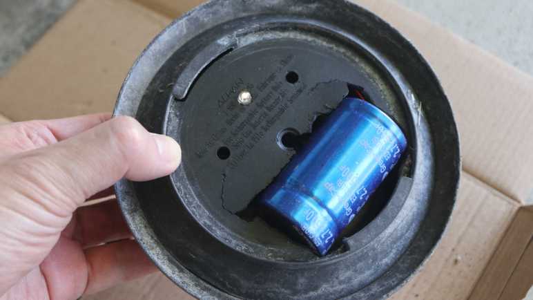
I have eight solar lawn lights in my yard, and sitting under the sun for several years has taken its toll. Even though they’re basically disposable, I thought I would play with them before throwing any away. I tried to retrofit one with a super capacitor and the attempt taught me several problems not the least of which is that those supercapacitors I bought were too big fit inside. I had better results from my first experiment swapping out a NiMH battery. For the foreseeable future, I think that’s the way to go.

Since my capacitor test light turned out to have a dead solar cell, I used my bench power supply set to 2V as the power source. I charged it up during the day, then disconnected power at sunset to see how long it ran. It shut off a little over six hours later which is roughly the runtime I want out of these lights. It’s also on par with what I get out of running these lights on salvaged NiMH batteries past their prime.

I had contemplated trying my supercapacitor test again with smaller capacitors that would easily fit inside, but physically smaller capacitors would have less energy storage capacity as well. Which means they can’t run as long, and my light would go out sooner. I could compensate for this by wiring several smaller units in parallel, distributed around the light’s interior instead of one big cylinder, but then cost would go up.

The capacitors I bought were advertised as 500F. Given the realities of no-name Amazon vendors I doubt that number is accurate, but it is a starting point for comparison. There are smaller capacitors available roughly the size of my salvaged NiMH cells, which I know would fit with minimal trouble. Maybe even a pair of them. The highest-capacity units I found at that size (*) were advertised as 100F and cost more than my “500F” units. If it runs the lights for 1/5 as long, the lights would only illuminate for a little over an hour before going out. Even a pair working in parallel would go dark in less than two hours, and that’s too short.

I would expect supercapacitors to withstand daily charge/discharge for many years with minimal degradation. But as things stand I would have to pay a price premium and give up significant runtime and even then the solar cell may die first. I don’t think that tradeoff makes sense so I’ve decided to stay with NiMH batteries for now and possibly reevaluate supercapacitor price/performance again in a few years. Especially since I discovered past me had stashed a batch of lights I can use today.


(*) Disclosure: As an Amazon Associate I earn from qualifying purchases.

Solar Lawn Light Capacitor Experiment

I’m playing around with some old tired solar lawn lights I have in my back yard. I discovered their energy storage was in the form of AAA NiMH batteries, and as an experiment I was able to resurrect one lawn light with a salvaged NiMH battery cell. I expect it to die again soon, though, because this is a very stressful application. First, a solar ornament sitting under the summer sun gets really hot, near the top end of NiMH operating temperature range, if not beyond. And second, I discovered these lights use 2V solar panels and would pass that all the way to battery terminals for charging. This also exceeds the recommended NiMH voltage range. Excess power would be dissipated as heat, which aggravates the temperature issue.

Given the limited expected lifespan of NiMH battery in this application, I thought it was a good opportunity to play with a supercapacitor. A relatively new branch of the capacitor family tree, they offer several orders of magnitude more energy storage capacity than other capacitor types though still less than commodity batteries. The types I can realistically purchase and play with can comfortably operate at summer heat temperatures, and their maximum voltage of 2.7V has a comfortable margin over solar cell output. Another key capacitor advantage over batteries are their tolerance for high charge and discharge rates, but that’s not important here. Most importantly, prices have dropped enough for me to pick up a batch to play with. I went on Amazon and bought the highest Farad-per-dollar listing I found that day. (*) Once it arrived, I selected another lawn light for this capacitor experiment.

Electrical Failure: Solar Cell

Having established that the YX805 chip at the heart of these lights won’t do anything when the battery is below 0.9V, I used my bench power supply to charge my capacitor up to a NiMH-emulating 1.25V.

I un-soldered the battery compartment wires and soldered them to the YX805 circuit board. The LED illuminated. This is good! Since my solar panel was facing downwards, this is appropriate behavior for a dark environment with energy in the battery.

I then moved the assembly to a bright sunlit spot, and the LED continued shining. This is bad! It was supposed to go into battery-charging mode. Probing with my volt meter, I established the solar cell is not delivering any power so the YX805 chip thinks it’s always dark.

Mechanical Failure: Brittle Plastic

Even if the solar cell was still functioning, I would not have been able to put this light back together. The plastic bracket directly underneath the solar cell had degraded under heat.

There were four screws fastening the bottom and top covers together. When I started turning those screws, three of these corner posts crumbled apart. That left only one superficially intact, but the threads crumbled during removal so that final fourth post is just as useless as the rest. I can’t install a replacement solar cell, as the dead cell and mounting posts were held with this glob of gray epoxy. Which, inconvenient for me, is still holding strong. If the solar cell was still good and I wanted to repair this mounting mechanism, I would have to design, 3D print, and epoxy something that sits apart from this crumbled assembly.

Mechanical Failure: Not Enough Room

The good news: a dead solar cell and broken mount meant I was free to experiment with fitting a capacitor inside. This capacitor is slightly larger than a D-size battery cell, and I’m trying to fit it in a device designed for AAA-sized cells.

I took a chisel and cut out the battery tray, which also took out two of the four mounting screw holes, but they had nothing to fasten to anyway. This tray is made of plastic and almost as brittle as the top bracket. Pieces of plastic crumbled under the chisel as I went.

I quickly made a hole big enough for the capacitor to fit, but not enough for the two halves to close together. I started an iterative process of “make hole bigger” and “test fit” then repeat. I made the hole larger and larger until it started encroaching upon the LED hole in the center. To make room, I turned the LED circuit board 180 degrees and drilled a small hole for LED to shine from an off-center position.

By the time I can close the two halves together, the capacitor was about half-exposed to the outside. Moving it further center would make the problem worse, because the solar panel bracket assembly would force the capacitor further away so more than half of it would be exposed out the bottom. And as it happens, I would need to move further center: I had put the capacitor too close to the outer edge, cutting into volume required for the glass component beneath. Fail! Fails all around, ah well. But it was fun to try. Now I know enough to decide I should stick with NiMH batteries.


(*) Disclosure: As an Amazon Associate I earn from qualifying purchases.

Solar Lawn Light NiMH Battery Replacement

Years ago I bought an 8-pack of solar lawn lights. They were fun for lighting up the back yard for a few hours after sunset, and I was curious how long they’d last. The answer was about five years, plus or minus a few years, depending on your standards because they gradually fade out. Both in terms of shorter duration after sunset, and in terms of dimmer illumination.

Now only one of the original eight offer any visible illumination, for less than half an hour after sunset. This behavior implies whatever internal energy storage device has degraded over years, and I wanted to take a look to see if I can confirm my hypothesis.

Solar lawn lights are very inexpensive now, and it’s much easier to just buy a new set. The reason I wanted to try reviving these lights is because their center clear section is glass, not clear plastic as many current products use.

Glass won’t yellow and fail after years of southern California sunshine, which is not something I can say for whatever non-glass material was used for the solar cell’s top layer. The paint is also very visibly damaged by sunlight. I can repaint if I want to, but condition of that solar cell looks bad.

Flipping the lid over, I was surprised to see a battery compartment door. I had expected a “no user serviceable parts inside” arrangement. I opened the door and the molded plastic latch broke, brittle from years of baking under the sun.

Inside the door is a AAA NiMH battery cell, literally roasted by the sun while it lived inside a black enclosed compartment. After removing the battery, I took a multimeter and measured the open-circuit battery compartment terminals under sunlight. My meter read 2.095 volts. Yikes! That’s a lot higher than the 1.25V nominal level for a NiMH battery cell. Are NiMH batteries expected to take this kind of abuse? I know NiMH batteries can handle over-voltage better than lithium chemistry batteries, but I didn’t know to what degree. While excess energy can be dissipated as heat, it’s hard to shed energy as heat when it is already very hot from sun. Between the high voltage and high temperature, these cells lived a harsh life.

Looking in my pile of NiMH batteries, I found two AAA-sized units and installed one of them. The LED lit up when I covered the solar panel to simulate night, so I decided the old battery must be completely dead. To my surprise, it wasn’t! When I connected it to my “Joule Thief“, the LED lit up and stayed illuminated for days. The battery isn’t completely dead, but not well enough to run this solar lawn light. Connecting it to my bench power supply, I find the LED turns off when battery voltage drops below about 0.9V. In comparison, my Joule Thief will run all the way down to about 0.4V, which is much more demanding on the battery and a bad idea for longevity.

I don’t have many NiMH AAA batteries on hand. I could buy some more, but I don’t particularly relish the thought of buying new batteries just to sentence them to a quick and hot death. I decided to open up the light to see inside. There wasn’t much: the solar panel is well-sealed by a blob of dark gray epoxy, and there’s only a tiny circuit board inside.

The back of the circuit board shows all the signs of something left out in the elements.

As does the front, which showed a YX805 chip in charge of the operation. An online search found a Simplified Chinese datasheet which explained it was specifically designed to run solar lawn lights. Machine translation claimed battery over-discharge protection as a feature, explaining the deactivation at 0.9V. There’s also mention of adjustable battery charge rate, but nothing about over-voltage protection. Either the machine translation missed it, or the designers decided it was OK for a 1.25V nominal voltage NiMH battery cell to face 2.095V charging input. Or perhaps the 2.095V I measured was just an artifact of an open circuit that fails to trigger the battery charge rate limiter?

Given its corroded condition implying it may fail elsewhere in short order, I’m not eager to spend money on new batteries. I have plenty of NiMH cells on hand, though, just not in AAA size. The biggest of which are from Neato battery packs. They’re too old and tired to run a robot vacuum, but perhaps they can run a solar lawn light. I cut the spot-welded tabs in half and soldered to the half-tabs, sparing battery cells from heat of my soldering iron.

Sadly many of those old cells were too weak to get up over that 0.9V minimum bar, but a few of them were good enough to run a solar lawn light (though dimly) for a bit after sunset. Perhaps my solar lawn lights will be my way of giving some old NiMH battery cells yet another life, even if a hot and short one. Or I can use it as motivation to explore another technology: supercapacitors.

Lithium Iron Phosphate Battery UPS Runtime Test #2 (9 Months)

I have several UPS (uninterruptable power supply) units to keep important electronics running through short power outages. Designed for SLA (sealed lead-acid) batteries in a commodity 12V (volt) 7AH (amp-hour) form factor, I retrofitted one of my UPS with LFP (lithium iron phosphate) battery packs designed to the same form factor for use as a drop-in retrofit. I performed the first runtime test immediate after they were installed, intending to repeat the test at regular intervals. I had thought repeating the test every 6 months would be informative, but I recently realized it’s been 9 months. Oops. Well, it should still be informative. All the same equipment are still plugged in to this UPS, so the test was a matter of setting aside a period of time when I can be interrupted every 5 minutes to write down the estimated runtime remaining displayed on the UPS. Then those numbers were plotted on the same Excel spreadsheet to generate this chart:

The new line (in orange) is slightly lower than the line from the first test, but behaved mostly the same indicating minimal degradation after 9 months. It shares the odd initial jump to 295 minutes estimated runtime as soon as I unplugged it, and two large drops I can’t explain. By the 75 minute mark estimates from this second test were 5-10 minutes lower than the first test until 165 minutes when the two matched up. I wouldn’t put too much weight on that, though, as the first test established that runtime estimate became unreliable around this point due to different discharge curves between SLA and LFP battery chemistries.

I stopped this test after 210 minutes, or three and a half hours. Given the unreliable time estimate beyond 180 minutes, I expected no useful data from draining this UPS further. I was satisfied my UPS can still keep my components running for at least that long, which I felt was the most important part.

I didn’t intend for a 9 month test interval, but now that the precedence has been set, I’ve set a calendar reminder for myself to repeat this test at the 18-month mark: Test #3 is scheduled for April 2025.

Adafruit Memento + AMG8833: Upgrade Scotch Tape to Servo Tape

I taped an AMG8833 thermal sensor to my Adafruit Memento camera to create a thermal vision camera, and finally got my code fast enough to keep up with the sensor’s speed limit at around ten frames per second. It turned out to be a great practice lesson in CircuitPython performance optimization! Now I need to wrap up some loose ends.

There was one little change on the software side: because I’m using color to represent temperature, sometimes color in the real world can be confusing. So I flipped the visual camera mode to black-and-white ensuring all color visible on screen comes from thermal data.

Then I worked on improving how the AMG8833 is mounted. I used cellophane tape because it was quick and easy and good enough for me to start experimenting. But it’s pretty fragile and would not fit in the Memento carrying case that came as part of Adabox 021. Now that the experiment is a success, it’s worth effort to make a better mount.

The sensor is now protected by a bit of transparent heat-shrink tubing, and the wires were re-soldered so they exit out the side instead of back.

I then used some double-sided foam tape to attach the sensor module closer to the visual camera module. This position blocked three of the front panel LEDs but I haven’t been using them anyway.

And now it fits in carrying case! I thought having a thermal camera would be neat, but I was never sure how much I would actually use one. Now I have a low resolution DIY version, I’ll see if it comes in handy. I can see several future possibilities:

  1. I might take this apart for another project idea. For one thing, this project didn’t make use of Memento’s photography capabilities at all and I think that’s a shame.
  2. Maybe I’ll upgrade to a better sensor module breakout board.
  3. Maybe I’ll decide a thermal camera is useful enough to finally buy a FLIR ONE for myself.

Time will tell.

For now, I’m still thinking about electronics that help me see what I can’t see with my own eyes. Thermal cameras do that, and so do microscopes.

Adafruit Memento + AMG8833: NumPy and List Comprehension

Pairing an AMG8833 thermal sensor with an Adafruit Memento camera gave me a thermal camera, but my code was running quite slowly. I found an example illustrating use of (ulab.numpy subset of) NumPy for interpolating data from AGM8833’s sensor grid to a larger grid, and adapted it to my project. My performance marker timers say this resulted in total of ~320ms per frame, or roughly 3 frames per second. Here’s an excerpt from rendering four frames:

read 38028 scaled 596 mapped 1520 blit 27626 grid 224501 refresh 24528 total 316799
read 38237 scaled 596 mapped 1520 blit 28789 grid 223636 refresh 24438 total 317216
read 38296 scaled 566 mapped 1580 blit 27567 grid 226170 refresh 24438 total 318617
read 38356 scaled 626 mapped 1728 blit 28849 grid 198901 refresh 24587 total 293047

More important than the interpolation itself was having an example for me to study NumPy. My takeaway is to avoid writing loops iterating through arrays as much as possible. Almost every performance win here boils down to substituting a tightly iterating loop with a single operation.

Bitmap as NumPy Array

The biggest win was converting my thermal overlay drawing commands into a single NumPy operation. The critical part is creating a ndarray view on top of existing bitmap data in order to avoid copying its bits around.

output_ndview = np.frombuffer(output_bitmap,dtype=np.uint16).reshape((240,240))

This was the key allowing me to describe large scale bitmap operations without having to write my own for loops to iterate over x,y coordinates. The loops are still happening, of course, but now they’re within fast native code free of Python runtime overhead.

Subset Blues

I knew ulab.numpy was a subset of full NumPy and was curious if the missing parts would be something I wished for or if they’re too esoteric and I wouldn’t miss their absence. The answer is the former: even as a beginner I quickly ran into situations where I found a NumPy answer on something like a Stackoverflow thread only to find features missing from ulab.numpy. One example is repeat(), which I replaced with my own series of unrolled copy operations.

List Comprehension For Palette Lookup

The final bit of code to be replaced by NumPy operations was a thermal color palette lookup. My first implementation did it easily with nested for loops iterating through x and y axis, but it’s not fast. This feels like an operation that might have a NumPy operator, but nothing in ulab.numpy sounded applicable. Full NumPy offers a way to execute an arbitrary Python function over every element in an array, but that was missing from ulab.numpy. After reading through several Stackoverflow threads I decided to create a list comprehension out of palette lookup and build a NumPy array around the list. I’ve already explained why I didn’t like list comprehensions, but performance numbers don’t lie: performing palette lookup via list comprehension was at least an order of magnitude faster. For that kind of gain, I’ll hold my nose and use a list comprehension.

Final Results

I’ve replaced almost every for loop in my old code with NumPy operations, the only remaining inner loop for generates my list comprehension. All of these changes add up to quite an improvement. As can be seen in these times involved in generating four frames:

read 38624 scaled 775 interpolated 1132 mapped 2444 blit 28551 grid 6199 refresh 25361 total 103086
read 38624 scaled 626 interpolated 924 mapped 2175 blit 28730 grid 33319 refresh 25153 total 129551
read 38594 scaled 685 interpolated 1043 mapped 2295 blit 27716 grid 6288 refresh 25452 total 102073
read 38504 scaled 656 interpolated 924 mapped 2295 blit 28044 grid 33289 refresh 25213 total 128925

As low as 102ms, almost 10fps, which is great! In fact, it marks the finish line. 9-10fps is as fast as the AMG8833 can deliver due to legal limitations imposed on thermal sensors. Going faster won’t gain anything thus ends this practice session of CircuitPython performance optimization. I will wrap up a few details and move on to the next project.


https://github.com/Roger-random/circuitpython_tests/blob/main/pycamera_amg88xx/code.py

Adafruit Memento + AMG8833: Add Interpolation

I paired an AMG8833 thermal sensor with my Adafruit Memento camera to build a thermal camera. I expected it to be an instructional learning project, I just didn’t expect it to be a learning project about CircuitPython performance. First step was to add performance timers to quantify impact of future enhancements, which gave me a baseline. Here’s an excerpt reflecting four frames rendered using TileGrid:

read 38087 scaled 3099 mapped 1789 grid 1728 blit 28223 refresh 360370 total 433296
read 37789 scaled 3099 mapped 1759 grid 1758 blit 30190 refresh 359803 total 434398
read 38713 scaled 3129 mapped 1788 grid 1729 blit 29683 refresh 362098 total 437140
read 38296 scaled 3129 mapped 1758 grid 1759 blit 29146 refresh 360579 total 434667

Total time per frame of roughly 430ms means a little over 2 frames per second.

Back to Bitmap

I converted the code back to my naive dot-drawing code, which showed better numbers. Again, an excerpt of four frames:

read 37760 scaled 3368 mapped 1609 blit 27239 grid 146836 refresh 24468 total 241280
read 38266 scaled 3099 mapped 1580 blit 27239 grid 118077 refresh 24557 total 212818
read 38206 scaled 3368 mapped 1609 blit 27746 grid 144750 refresh 24527 total 240206
read 38237 scaled 3367 mapped 1610 blit 27269 grid 144750 refresh 24378 total 239611

My dot-drawing code is within the “grid” bracket and that’s why it got a lot slower. And “refresh” is technically wrong as I’m no longer calling display.refresh(). I’m actually calling pycam.blit() but since I’m already using the “blit” label for something else I left the label as “refresh”.

At a total cycle time of under 240ms, this was about 4 fps and almost double the speed of my TileGrid version. This is still very slow but the good news is the slowest parts are now code under my control.

Add Interpolation

With code under my control, NumPy experiment begins. I started by adapted PyGamer Thermal Camera code to my project. It replaced my old code within “scaled” and output a 15×15 array of interpolated values. Despite this added functionality, execution time dropped from ~3.3ms to ~0.6ms. Nice!

Unfortunately overall frame rate dropped from ~4fps to ~3fps because “grid” got slower: it now has to draw a thermal overlay of 15×15 data points instead of just 8×8.

read 38028 scaled 596 mapped 1520 blit 27626 grid 224501 refresh 24528 total 316799
read 38237 scaled 596 mapped 1520 blit 28789 grid 223636 refresh 24438 total 317216
read 38296 scaled 566 mapped 1580 blit 27567 grid 226170 refresh 24438 total 318617
read 38356 scaled 626 mapped 1728 blit 28849 grid 198901 refresh 24587 total 293047

Slower frame rate is only a temporary setback, because this example helped me learn how (the ulab.numpy subset of) NumPy can be applied to my project. These lessons helped me unlock additional performance gains.

Adafruit Memento + AMG8833 Overlay: Performance Timers

I’ve successfully overlaid data from a AMG8833 thermal sensor on top of the Adafruit Memento camera viewfinder, turning it into a thermal camera. A very slow and sluggish thermal camera! Because my first draft was not written with performance in mind. To speed things up, I converted my thermal overlay to use TileGrid and take advantage of the compositing engine in Adafruit’s displayio library. In theory that should have been faster, but my attempt was not and I didn’t know how to debug it. I went looking for another approach and found MicroPython/CircuitPython has ported a subset of the powerful Python NumPy library as ulab.numpy. And furthermore, there was an example of using this library to interpolate AGM8833 8×8 data to a 15×15 grid in Adafruit learning guide Improved AMG8833 PyGamer Thermal Camera. Ah, this will do nicely.

Add Performance Timers

The first thing I got from that project is a reminder of an old lesson: I need to record timestamps during my processing so I know which part is slow. Otherwise I’m left with vague things like “TileGrid didn’t seem much faster”. I added several lines of code that recorded time.monotonic_ns() and a single line at the end of my loop that print() delta between those timestamps. Since the units are nanoseconds and these are slow operations, I get some very large numbers that were unwieldy to read. Instead of dividing these numbers by 1000, I right-shifted them by 10 bits to result in a division by 1024. The difference between “roughly microseconds” and “exactly microseconds” is not important right now and, in the spirit of performance, should be much faster.

Measure TileGrid Implementation

Here’s are four frames from my TileGrid implementation:

read 38087 scaled 3099 mapped 1789 grid 1728 blit 28223 refresh 360370 total 433296
read 37789 scaled 3099 mapped 1759 grid 1758 blit 30190 refresh 359803 total 434398
read 38713 scaled 3129 mapped 1788 grid 1729 blit 29683 refresh 362098 total 437140
read 38296 scaled 3129 mapped 1758 grid 1759 blit 29146 refresh 360579 total 434667

With a total of ~434ms per loop, this is just a bit over two frames per second. Here’s the breakdown on what those numbers meant:

  • “read” is time consumed by reading 8×8 sensor data from AMG8833 sensor. This ~38ms is out of my control and unavoidable. It must occur for basic functionality of this thermal camera.
  • “scaled” is the time spent normalizing 8×8 sensor data points between the maximum and minimum values read on this pass. This ~3ms is my code and I can try to improve it.
  • “mapped” is the time spent translating normalized 8×8 sensor data into an index into my thermal color palette. This ~1.7ms is my code and I’m surprised it’s over half of “scaled” when it does far less work. Perhaps ~1.7ms is how long it takes CircuitPython to run through “for y in range(8): for x in range(8):” by itself no matter what else I do.
  • “grid” is the time spent updating TileGrid indices to point to the color indices calculated in “mapped”. Since it’s basically the same as “mapped” I now know updating TileGrid indices do not immediately trigger any bitmap processing.
  • “blit” copied OV5640 sensor data into a bitmap for compositing. This ~30ms is out of my control and unavoidable. It must occur for basic functionality of this thermal camera.
  • “refresh” is where most of the time was spent. A massive ~360ms triggered by a single line of my code. This included pulling bitmap tiles based on TileGrid indices, rendering them to the TileGrid, compositing thermal overlay TileGrid on top of the OV5640 bitmap TileGrid, and finally send all of that out to the LCD.

Back to Bitmap

I don’t know why my TileGrid compositing consumed so much time. I’m probably doing something silly that crippled performance but I don’t know what it might be. And when it’s all triggered by a single line of my code, I don’t know how to break it down further. I will have to try something else.


https://github.com/Roger-random/circuitpython_tests/commit/1a62d8adbbeecf9d05ad79ff239906367fbfb440

Adafruit Memento + AMG8833 Overlay: TileGrid

By overlaying data from AMG8833 thermal sensor on top of the Adafruit Memento camera viewfinder, I’ve successfully turned it into a thermal camera. The bad news is all of my bitmap manipulation code runs very slowly, bogging the system down to roughly a single frame per second. I blame my habit or writing Python code as if I were writing C code. Running tight loops shuffling bits around is fine in C, but now the same approach is incurring a lot of Python runtime overhead.

As I understand Python, the correct approach is to utilize libraries to handle performance-critical operations. My Python code is supposed to convey what I want to happen at a higher level, and the library translates it into low-level native code that runs far faster. In this context I believed I needed CircuitPython displayio sprite compositing engine to assemble my thermal overlay instead of doing it myself.

The viewfinder image is pretty straightforward, loading OV5640 into a Bitmap which went into a TileGrid as a single full-screen entry. The fun part is the thermal overlay. I created a TileGrid of 8×8 tiles, matching thermal sensor output data points. I then created another bitmap in code corresponding to my range of thermal colors. I didn’t see any option for alpha blending in displayio and, as I believed it to be computationally expensive, I wanted to avoid doing that anyway. My palette bitmap is again a screen door of my thermal color alternating with the color marked as transparent so viewfinder image can show through.

In theory, this means every thermal sensor update only requires updating tile indices for my 8×8 TileGrid, and displayio will pull in the correct 30×30 pixel bitmap tile to use as a sprite rendering my 240×240 pixel thermal overlay. The underlying native code should execute this as native code memory operation far faster than my loop in Python setting bitmap pixels one by one.

I had high hopes, but I was hugely disappointed when it started running. My use of TileGrid did not make things faster, in fact it made things slower. What went wrong? My best hypothesis is that compositing tiles with transparent pixels incur more workload than I had assumed. I also considered whether I incurred color conversion overhead during compositing, but as documentation for displayio.Palette claimed: “Colors are transformed to the display’s format internally to save memory.” So in theory color conversion should have been done once during startup when I created the thermal color tiles, not during the performance-critical loop.

The upside of Python’s “offload details to libraries” approach is that I don’t have to understand a library’s internals to gain its benefits. But the corresponding downside is that when things go wrong, I can’t figure out why. I have no idea how to get insight into displayio internals to see what part of the pipeline is taking far longer than I expected. Perhaps I will eventually gain an intuition of what is quick versus what is computationally expensive to do in displayio, but today it is a bust and I have to try something else.


https://github.com/Roger-random/circuitpython_tests/commit/650f46e64bc08de9f8c1f451a4d18ea7021e92fb

Adafruit Memento + AMG8833 Overlay: Alpha Blending

The AMG8833 thermal sensor I taped to an Adafruit Memento camera is successfully communicating with the ESP32-S3 microcontroller running Memento, and I can start working on integrating data from both thermal and visual cameras.

Goal

Low resolution thermal data can be difficult to decipher, but overlaying low-resolution thermal data on top of high-resolution visual data helps provide context for interpretation. This is a technique used in commercial thermal imaging products. The most accessible devices are designed to plug into my cell phone and utilize the phone for power and display. For my Android phone, it’ll be something like this FLIR One unit.(*) I’ve thought about buying one but never did. Now I will try to build a lower-cost (though far less capable) DIY counterpart.

Precedence

For code functionality, there’s a useful precedence in Adafruit’s “Fancy Camera” sample application: it has a stop-motion animation mode which shows the previously captured frame on top of the current viewfinder frame. This allows aspiring stop-motion animators to see movement frame-to-frame before committing to a shot, but I want to try using its overlay mechanism for my purposes. On the source code side, this means following usage of the data objects last_frame and onionskin. They led me to bitmaptools.alphablend(). Performing alpha blending on a microcontroller is not fast, but it was a good enough starting point.

Drawing Thermal Overlay

Now that I’ve found a helper to blend the viewfinder image with my thermal data, I have to draw that thermal data. The small LCD on board Memento has a resolution of 240×240 pixels, and that divides neatly into 8×8 sensor resolution. Each sensor data point corresponds to a 30×30 pixel block of screen. Drawing solid squares was really, really slow. I opted to draw every third pixel vertically and horizontally, which means drawing a dot for every 3×3=9 pixels. This lent a screen door effect to the results that was, again, good enough as a starting point.

Thermal Color Spectrum

Commercial thermal cameras have established a convention for color spectrum representing thermal data. Black represents cold, blue is a bit warmer, then purple, red, orange, yellow, all the way to white representing the hottest portion of the picture. I started mapping out a series of RGB values before I noticed that spectrum is conveniently half of a HSV hue wheel. I went looking for a CircuitPython library for HSV color space and found FancyLED. Calling pack() gave me a representation in RGB888 format instead of the RGB565_SWAPPED format used by Memento LCD. I didn’t find an existing conversion utility, but I’m a C programmer and I’m comfortable writing my own bit manipulation routine. It’s not the fastest way to do this, but I only have to build my palette once upon startup so it’s not a concern for the performance-critical inner display loop.

    # Obtain hue from HSV spectrum, then convert to RGB with pack()
    rgb = fancy.CHSV(hue, saturation, value).pack()

    # Extract each color channel and drop lower bits
    red =   (rgb & 0xFF0000) >> 19
    green_h3 = (rgb & 0x00FF00) >> 13
    green_l3 = (rgb & 0x003800) >> 11
    blue =  (rgb & 0x0000FF) >> 3
    # Pack bits into RGB565_SWAPPED format
    rgb565_swapped = (red << 3) + (green_h3) + (green_l3 << 13) + (blue << 8)

Orientation

I was happy when when I saw my thermal color overlay on top of the viewfinder image, but the two sets of data didn’t match. I turned on my soldering iron for a point source of heat, and used that bright thermal dot to determine my thermal sensor orientation didn’t match visual camera orientation. That was easily fixed with a few adjustments to x/y coordinate mapping.

Field of View

Once the orientation lined up, I had expected to adjust the scale of thermal overlay so its field of view would match up with the visual camera’s field of view. To my surprise, they seem to match pretty well right off the bat. Of course, this was helped by AGM8833’s low resolution giving a lot of elbow room but I’m not going to complain about having to do less work!

Too Slow

At this point I had a first draft that did what I had set out to do: a thermal overlap on top of visual data. It was fun taking the camera around the house pointing at various things to see their thermal behavior. But I’m not done yet because it is very sluggish. I have plenty of room for improvement with performance optimization and I think TileGrid will help me.


(*) Disclosure: As an Amazon Associate I earn from qualifying purchases.

https://github.com/Roger-random/circuitpython_tests/commit/30e24717cad579a0cc05f4b381d5f637259fe4bb

Adafruit Memento + AMG8833 Initial Bootstrap

I’ve taped an AMG8833 thermal sensor to the side of an Adafruit Memento camera, just a quick hack for mechanical attachment while I experiment. I want to get them to work together and show something interesting, which means I need to figure out the software side. Here were my initial bootstrap steps:

Boarding An Existing I2C Bus

The first test was to see if the device is properly visible on Adafruit Memento’s I2C bus. Adafruit sample code failed when it tried to create a I2C busio object because it was written with an implicit assumption the AMG8833 was the only I2C device present. When mounted on an Adafruit Memento, I need to grab the existing I2C object instead of creating a new one.

Data Elements Are Floating Point Celsius

One thing that I didn’t see explicitly called out (or I missed it) was the format of data points returned by calling Adafruit library. Many places explaining it will be an 8×8 list of list. That is, a Python list of 8 elements where each of those elements is a list of 8 data points. But what are the individual data points? After printing them to console I can finally see each data point is a floating point number representing temperature reading in Celsius.

I2C Operation On Every pixels Property Getter Call

One lesson I had to learn was to be careful how I call the pixels property getter. One of the sample code snippets had this:

for row in sensor.pixels:
    for temperature in row:
        ...[process temperature]...

And while I was experimenting, I wrote this code.

for y in range(8):
    for x in range(8):
        sensor.pixels[y][x]

Conceptually they are very similar, but at run time they are very different. Mine ran extremely slowly! Looking at the library source code revealed why: every call to the pixels property getter initiates an I2C operation to read the entire sensor array. In the first loop above, this happens once. The second loop with my “write Python like C code” habit meant doing that 64 times. Yeah, that would explain why it was slow. This was an easy mistake to fix, and it didn’t take much more effort before I had a working first draft.

AMG8833 Module Finally Unwrapped

I’ve been learning CircuitPython library implementation for Adafruit Memento (a.k.a. PyCamera) with the goal of doing something interesting beyond published examples. After brainstorming a few candidates, I decided to add an AMG8833 thermal sensor alongside. Mainly because I bought an Adafruit breakout board thinking it was neat and had yet to unwrap it. Today is the day.

According to my Adafruit order history, I bought this way back in 2018. Look at how faded that label has become. Over the past six years several project ideas had come and gone, the most recent one I can remember being an ESP32 web app like what I had built for the AS7341 spectral/color sensor. But none of them got far enough for me to unwrap this roll of pink bubble wrap.

Since the time I bought my sensor, Adafruit has added a higher-resolution thermal sensor to their product list. I told myself not to spend money on the newer fancier sensor until I actually use the one I had already bought. During this time Adafruit has also evolved the design, adding a STEMMA QT connector.

If I had one of the newer boards, I wouldn’t need to do any soldering. The Memento has a STEMMA QT port and this little cable would connect them together.

But since I have the old board, I cut the cable in half so I can solder wires and plug the other end into Memento.

For mechanical mounting, I thought I would use one of the existing mounting holes and bolt it to a Memento corner post. It’d be quick and easy but unfortunately the hole diameter is just a tiny bit too small for this idea to work.

With that idea foiled, my brain started thinking about alternate approaches that grew more and more elaborate. I didn’t want to invest in the time and effort because I didn’t even know if this idea would work. I taped it down for the sake of expedient experimentation until a proof-of-concept first draft is up and running. Time to start coding.

KMK Firmware Revives Acer Aspire Switch 10 Keyboard Module

Right now I’m playing with the keyboard module salvaged from a dead Acer Aspire Switch 10. A CircuitPython program running on a Raspberry Pi Pico helped decipher its matrix layout, much more quickly than it would have been for me to figure it out manually with my multi-meter. To test this information, the obvious next step is to turn this into an actual USB HID keyboard. Since I’m already in the realm of CircuitPython, I followed Adafruit’s link to KMK firmware. KMK was written in CircuitPython which means I don’t even have to re-flash the runtime on my Raspberry Pi Pico, I could just change my code.

There are several ways to declare my keyboard matrix, most of the predefined KMK configuration files used the coord_mapping capability to give the keyboard layout in source code a rough resemblance to its physical layout. It’s nice for user-friendliness and ease of customization, but I’m going to skip that step for my initial test. I decided to go with the straightforward keymap list which is strictly in electrical matrix layout, paying no attention to its physical layout. This was easy for me because I had already built the table earlier so I just need to translate it into KMK CircuitPython code:

keyboard.col_pins = (board.GP12,board.GP13,board.GP14,board.GP15,board.GP16,board.GP17,board.GP18,board.GP19)
keyboard.row_pins = (board.GP1,board.GP2,board.GP3,board.GP4,board.GP5,board.GP6,board.GP7,board.GP8,board.GP9,
    board.GP10,board.GP11,board.GP20,board.GP21,board.GP22,board.A0,board.A1)

keyboard.keymap = [
    #12         13          14          15          16          17          18          19          Keyboard pins
    [KC.NO,     KC.UP,      KC.NO,      KC.NO,      KC.NO,      KC.DOWN,    KC.ESCAPE,  KC.NO,      # 1
     KC.BSPACE, KC.DELETE,  KC.RBRACKET,KC.QUOTE,   KC.NO,      KC.NO,      KC.NO,      KC.ENTER,   # 2
     KC.PGUP,   KC.NO,      KC.BSLASH,  KC.PGDOWN,  KC.NO,      KC.NO,      KC.NO,      KC.NO,      # 3
     KC.PSCREEN,KC.INSERT,  KC.EQUAL,   KC.LBRACKET,KC.NO,      KC.DOT,     KC.C,       KC.NO,      # 4
     KC.MINUS,  KC.PAUSE,   KC.NO,      KC.L,       KC.M,       KC.COMMA,   KC.SPACE,   KC.LEFT,    # 5
     KC.F12,    KC.F11,     KC.NO,      KC.N9,      KC.K,       KC.J,       KC.N,       KC.O,       # 6
     KC.F10,    KC.F9,      KC.N8,      KC.N7,      KC.I,       KC.H,       KC.B,       KC.U,       # 7
     KC.F8,     KC.F7,      KC.N6,      KC.T,       KC.G,       KC.V,       KC.NO,      KC.Y,       # 8
     KC.F6,     KC.F5,      KC.N5,      KC.E,       KC.D,       KC.F,       KC.NO,      KC.R,       # 9
     KC.F4,     KC.F3,      KC.N3,      KC.N4,      KC.S,       KC.RIGHT,   KC.NO,      KC.W,       # 10
     KC.F2,     KC.F1,      KC.N1,      KC.N2,      KC.A,       KC.Z,       KC.X,       KC.Q,       # 11
     KC.NO,     KC.NO,      KC.LSHIFT,  KC.SLASH,   KC.NO,      KC.RSHIFT,  KC.NO,      KC.NO,      # 20
     KC.NO,     KC.LCTRL,   KC.NO,      KC.N0,      KC.NO,      KC.NO,      KC.NO,      KC.NO,      # 21
     KC.LWIN,   KC.NO,      KC.NO,      KC.P,       KC.NO,      KC.NO,      KC.NO,      KC.NO,      # 22
     KC.NO,     KC.NO,      KC.NO,      KC.SCOLON,  KC.RALT,    KC.NO,      KC.LALT,    KC.NO,      # 23
     KC.GRAVE,  KC.NO,      KC.TAB,     KC.CAPSLOCK,KC.WINMENU, KC.NO,      KC.NO,      KC.NO,      # 24
     #                                       Special handling required for 19+24 = "Fn" ^^^^^
     ]
]

With this key map, I have a functional USB HID keyboard. (I typed part of this blog entry on it!) This is pretty cool, but it only scratches the surface of what KMK could do. I haven’t fully implemented this keyboard, either. There’s a “Fn” key that activates additional functionality. Fn+F4 has a “Zz” printed on it, and I interpret that to mean putting the computer into sleep mode. I think KMK’s “layer” functionality is how I would go about implementing it, but I went looking for a way to signal sleep key and didn’t find a KC.SLEEP or equivalent. Without that, I don’t have much motivation to figure out layers. A related problem was if I put the computer to sleep, this KMK keyboard does not wake the computer from sleep. I would have to investigate and address that behavior before I can use KMK to help build, for example, a Luggable PC Mark III.

I’ll leave that for the future. I’ve accomplished today’s goal of proving I could turn this salvaged keyboard module into an USB HID keyboard, and I’m satisfied with my answer.

For this hypothetical future project, I assume I will need to build a more compact circuit to replace my jumper wire monstrosity. Maybe even a custom PCB to host both my keyboard connector and my RP2040? Its actual form factor will need be dictated by project needs, which I don’t know right now so I’ll leave things be. While there’s no guarantee I’ll stick with KMK firmware, either, it’s pretty likely as I’ve decided I like CircuitPython a lot.

Acer Aspire Switch 10 Keyboard Matrix

I have a keyboard salvaged from an Acer Aspire Switch 10, and wired up a Raspberry Pi Pico microcontroller with the goal of running “Key Matrix Whisperer“. A CircuitPython program published by Adafruit to help automate the task of probing an unknown keyboard matrix.

To minimize confusion, I lined up pin numbers as much as I can between the keyboard FPC (flexible printed circuit) cable adapter and Pi Pico pin numbers. Adapter pin1 connected to Pi Pico pin GP1, adapter pin 2 to Pico pin GP2, etc. This worked up until pin 22. Because the Pico didn’t expose GP23 or GP24, adapter pin 23 was connected to the next available pin GP26 a.k.a. ADC0 a.k.a. A0 and adapter 24 went to GP27 a.k.a. A1. After creating my wiring harness I plugged it in and ran Key Matrix Whisperer. It worked exactly as advertised listing a pair of pins every time I held down a key.

I printed out a lightened grayscale picture of the keyboard so I can write pin numbers directly on each key. After iterating through all the keys, I learned this keyboard’s 24 wires are used in a 8×16 matrix for a maximum of 128 possible combinations. There were only 83 keys on this keyboard leaving 45 combinations unused. It feels rather inefficient to set up a matrix and use only ~2/3 of possible combinations. Perhaps this keyboard design is a simplified counterpart of a full keyboard that included a numeric keypad and other keys?

I ran Key Matrix Whisperer twice, and all but one key matched up on both runs. Number key 9 reported as 12+22 on my first pass but 6+15 on my second pass. Reviewing the chart, I see 12+22 is the Windows key. I must have accidentally pressed Windows while reaching for 9 on my first pass, and Key Matrix Whisperer registered the Windows key instead of my intended 9. I’m glad I went through a second confirmation pass and caught this mistake.

I don’t know of any keyboard matrix domain specific conventions on which set of pins are rows and which set are columns. By English language convention, columns are laid out left-right and rows are laid out top-bottom. But looking at this particular keyboard matrix, I didn’t notice any particular association between the pins and their physical locations, they seem to be all over the place. For example, pin 1 connects to the up and down arrows which are physically located in the lower right corner. Pin 1 also connects to the Escape key, which is diagonally opposite on the upper left corner. Absent any further understanding of how this matrix was formed, I decided the smaller set of 8 pins are columns for my own convenience: a matrix table that is narrower than it is tall (“portrait” and not “landscape”) is easier to fit here before I put this matrix table to work:

Pin1213141516171819
1UpDownEscape
2BackspaceDel]Enter
3Page Up\Page Down
4PrtSc
SysRq
Ins=[.C
5Pause
Break
LM,SpaceLeft
6F12F119KJNO
7F10F987IHBU
8F8F76TGVY
9F6F55EDFR
10F4F334SRightW
11F2F112AZXQ
20Shift
(Left)
/Shift
(Right)
21Control0
22WindowP
23;Alt Gr
(Right)
Alt
(Left)
24~TabCaps LockMenuFn

Jumper Wire Between Adapter And Pi Pico Skips Breadboard

I bought a FPC (flexible printed circuit) to DIP (dual in-line pins) adapter so I could explore the electrical behavior of a keyboard module I salvaged from a dead Acer Aspire Switch 10. After assembling the adapter, I realized I my original plan would not work. I had thought I could stick it on a breadboard and start with probing its pins with a multimeter and, with information from that probe, use jumper wires to build a test circuit. The first part won’t work because the adapter was designed so its DIP-sde pins were fully underneath without any part poking up above for my probe to touch. The second part won’t work because when the keyboard module FPC is installed, the cable blocks almost the entire left side. There’s enough room underneath if I want to use wires that travel horizontally, but not for the tall vertical ends of the quick test jumpers I had wanted to use.

Researching my options for plan B, I actually found a better way. My plan A of manually probing with a multimeter to determine keyboard matrix would have been a tedious process. I would have to try all combinations of pins and see which pair corresponded to each key. Tedious repetitious processes calls for automation! In this case, I found Adafruit had published a CircuitPython sketch (Key Matrix Whisperer) that would automatically cycle through all combinations of pins looking for continuity as I press individual keys. Wow, this sounds much easier.

To use the Key Matrix Whisperer I would need to wire up my keyboard adapter to a CircuitPython microcontroller. I was going to use the Adafruit KB2040 I had been using for CircuitPython experimentation, because the “Kee Boar” was originally designed for the scenario of building custom keyboards. Unfortunately it had only 20 accessible IO pins and I needed 24 here. So I pulled out my Raspberry Pi Pico with its 26 accessible pins already soldered with header pins. The new connection solution is to skip the breadboard and build a wiring bundle to directly connect adapter board to Pi Pico.

These jumper wires (*) came with individual 0.1″ pitch connectors. (I’ve seen these connectors listed as Dupont connectors, which is far too generic of a name.) While I could connect directly one-by-one, that implied a nightmare of single wires popping loose and having to figure out where they should go back to. In the interest of keeping things better organized, I popped off most of those single connectors and slotted them into longer connectors. (*) (The specific box I bought also called the connector type as JST-SM, except they are very clearly NOT JST-SM.) This only took a few extra minutes and I felt holding things together more securely was a good time investment. I don’t want to worry about loose connections as I decipher this keyboard matrix.


(*) Disclosure: As an Amazon Associate I earn from qualifying purchases.

Proto Advantage FPC Connector DIP Adapter (FPC080P030)

I want to learn more about a keyboard module I pulled out of an Acer Aspire Switch 10. And while the first step is to look at the actual wires involved in connecting such a thing, to get further I will need to probe electrical behavior of those wires. I went online to find a breakout board that I hoped would help me, and ordered a Proto-Advantage FPC080P030. (*) One side of this board has 0.8mm pitch contacts with flexible sizing able to accommodate up to 30 positions. Appropriate for soldering the kind of FPC (flexible printed circuit) cable connector I unsoldered from the Acer’s circuit board, which has 26 positions.

The business card that came with the kit pointed me to website for Proto-Advantage, where I found a huge catalog of adapter boards to bridge the world of surface-mount devices and 0.1″ pitch prototype perforated boards/breadboards. Looks like I am likely to buy more of their products in the future if I continue playing with salvaged electronics components. I went to check out their listing for the FPC080P030 I just bought. This is a company based in Canada. For their United States customers like myself, looks like it makes more sense to use Amazon logistics for distribution rather than trying to sell direct.

First task was to double check I bought the correct pitch to match my salvaged connector.

I was not looking forward to soldering 0.8mm pitch connectors one by one, but it turns out I didn’t have to. My soldering iron tip is far too big to work at this scale but all I had to do was drag a melted blob of solder across this row of pins. Between the solder mask on the Proto Advantage circuit board and copious use of soldering flux, surface tension did all the hard work. A quick meter check confirmed I have electrical continuity on all 26 pins and there were no bridges. Thanks, surface tension!

For the other side, there were no through-holes for adapting to 0.1″ pitch DIP format. I didn’t quite understand what I saw on product listing pictures but it made sense once I had all components in hand. The backside pads were laid out to go with right-angle 0.1″ headers, with their angled head pointing in alternate directions.

Proto Advantage bundled this assembly helper circuit board. There’s no copper to solder to here, its purpose is to hold all pins in a row within its drilled holes. This ensures all pins are soldered with the correct relative spacing to fit on a 0.1″ grid.

This specific board is, unfortunately, not breadboard jumper friendly. Inserting the keyboard module FFC would block off almost the entire left side. There’s a tiny bit of room to lay wires flat against the surface of the breadboard, but it won’t be possible to explore with jumper cables like I wanted. I’ll have to find another way, and it turned out to be a better way.


(*) Disclosure: As an Amazon Associate I earn from qualifying purchases.

Acer Aspire Switch 10 Keyboard Wiring

I want to experiment with turning a salvaged laptop keyboard module into a USB HID keyboard. My test subject is this keyboard pulled from an Acer Aspire Switch 10. I have successfully unsoldered its connector in the hopes I can solder it onto a breakout board I had ordered. While I wait for the board to be shipped to me, I can do a little scouting.

The easiest observation was that 2 out of 26 pins appear to be unused. They are present at the flex cable connector but immediately disappear into nothingness.

The remaining 24 wires are seen going into the keyboard module underneath a piece of black fabric tape. Peeling that tape off may gain more insight, but I’m not going to. Flex cables can only flex a finite number of times before something breaks, so I’m trying to keep handling and manipulation to a minimum.

Examining the circuit board, I looked for traces that are significantly wider than others or maybe wires that span multiple pins in parallel. Both are typical indications of power or ground wires, but I didn’t see anything of the sort. I then looked for components like decoupling capacitors or current-limiting resistors, and didn’t notice any good candidates either. This is consistent with my memory this keyboard was not backlit.

Looking on the back side, I see very few wires and they are mostly consistent with wires jumping over other perpendicular wires on the front. Not all of the vias lined up with traces I could see, which would be consistent with a circuit board with more than two layers. Though there are traces I couldn’t see, I think it is possible all 24 wires are connected directly to the chip adjacent to the now-unsoldered connector.

I read the chip marking as IT8595E-128 and the logo matches that of Taiwan-based ITE Tech, Inc. But there’s no IT8595E-128 listed on their product website today. The closest I found is an IT8596 under “Notebook product line”, advertised to be a laptop peripheral controller. Sounds about right, but there’s no datasheet download for me to see if it might be a sibling of this IT8595. Perhaps IT8595 is a discontinued product, or perhaps it was a custom design exclusive to Acer. Either way, I’m not going to get any more information here. To get any more information on how this keyboard module is wired, I will need to wait for my adapter board to arrive.

Dusting Off Acer Aspire Switch 10 Keyboard

Getting a tiny version of “Cat & Galactic Squid” running seemed like a good stopping point for my CircuitPython exploration with a Canon MX340 control panel. Now I want to go back and further explore CircuitPython’s keypad library. It included a KeyMatrix class for scanning large button matrices such as those used on a keyboard, which reminded me of a past project idea: repurposing a laptop keyboard. They are nice and compact, designed for easy integration into tight spaces, but they weren’t designed to be easily reused beyond the original laptop. I’ve disassembled several retired broken laptops and I’ve wished to turn them into compact USB keyboards. Maybe KeyMatrix can finally make that idea a reality.

Looking over my pile of salvaged components awaiting reuse, the best candidate (it was on top) was the keyboard I extracted from a broken Acer Aspire Switch 10. I liked how this small keyboard felt when I typed on it, and believed it would be good to put back in use.

While I can (and have in the past) soldered wires directly to flexible printed circuit (FPC) metal contacts, life would be much easier if I can use a real FPC connector. I used my handy Digi-Key PCB ruler to measure a pitch of 0.8mm. Given my recent discovery of vendors selling FPC connector breakout boards, I searched for 0.8mm pitch 26-pin breakout boards. Sadly, that combination was not popular enough to have a breakout board with pre-populated connector. The closest I found was a 0.8mm pitch breakout PCB with no connector but could accommodate up to 30 pins. (*)

I would have to either buy my own 26-pin connector or try to reuse the one I had. Since I like to salvage and reuse, I’m trying the reuse option first. The circuit board was placed on my MHP30 mini hot plate (*) and brought up to temperature.

The white plastic latch started to turn brown by the time solder melted, but all plastic components still seemed to be in their proper shape when I lifted this connector free. I think this is good enough for a try. If I fail with this connector, then I’ll spend money to buy another.

With the connector freed, and the breakout board ordered, I explored the wiring involved.


(*) Disclosure: As an Amazon Associate I earn from qualifying purchases.

Tiny Cat & Galactic Squid on MX340 LCD

I’ve verified that I now have full CircuitPython programmatic control over all input and output functionality available within the control panel of a Canon Pixma MX340 multi-function inkjet. The point of the exercise was to see if I could get this far. I would love to repurpose this control panel for a future project, but that is secondary. The perfect project would be one that needs a small LCD, numeric keypad, and a handful of task-dedicated buttons and LEDs. While I wait for such a project to come up, I could have some fun with a less serious project.

My friend Emily created Cat and Galactic Squid for me to use as demonstration content of my ESP32 composite video output library. I love this colorfully cheerful animation and have used it as test subject for several other projects. However, the MX340 LCD is monochrome and has only 196×34 pixels so I could not use the original cat & squid directly. I had to downscale it in an image editor, and manually fix up all the broken edges from such drastic down-sampling. And while I’m switching to monochrome, the cat is now modeled after one of Emily’s current cats “Hobie” with a suitable black and white tuxedo pattern. Getting the handful of pixels to remotely resemble a cat required that I go online to search for “pixel art cat” for some guidance.

There weren’t enough pixels to convey movement, so cat and squid would remain static. Neither were there enough pixels for that Saturn-like planet and a galaxy in the background, so the simplified version will only have vaguely circular dots of different diameters moving at different speeds for a parallax effect. Ideally I could use CircuitPython’s sprite bitmap compositing engine displayio to put all these elements together. Unfortunately I couldn’t figure out how to make this LCD compatible so I wrote my own crude compositing routine.

I originally thought I’d write this as an entirely separate MX340 demo app, but I realized I could incorporate it into the existing key echo feedback test app: a “screen saver”! Monochrome LCDs don’t really have burn-in issues that need saving, but it’s an user experience paradigm I can leverage. I switch to this animation if there aren’t any key presses for a while, and switch back as soon as a key is pressed. Integrating cat & squid was a nice bonus bit of CircuitPython practice.

https://github.com/Roger-random/canon_mx340/tree/main/control_panel_circuitpython

MX340 Control Panel Under RP2040 Control

I bought some FPC (flexible printed circuit) cables and connector breakout boards from Amazon vendors so I no longer have to solder wires directly to my salvaged Canon Pixma MX340 multi-function inkjet control panel. The first FPC breakout board went on a perforated prototype board to host a Raspberry Pi Pico. Up until this point I had been using Adafruit’s KB2040 board. But since they’re both based on RP2040 chip and have CircuitPython support, switching my code to run on a Pi Pico is a minor task of changing over a few pin names.

Soldering to the FPC breakout board with its 0.1″ (~2.54mm) pitch was far easier than the 1.0mm pitch of soldering directly to the control panel. Which meant I finally got around to connecting five wires that were previously not connected:

  1. 5 volt DC wire to supply WiFi LED
  2. LED+ for Power LED, in series with an 100 ohm current-limiting resistor already on board.
  3. LED+ for Alarm LED, also with resistor.
  4. Power button that is pulled to ground when pressed.
  5. Stop button that is pulled to ground when pressed.

My CircuitPython code had provision to set the appropriate bit flags to manipulate the WiFi LED, but I hadn’t tested it until this point due to lack of +5V power. I was happy to see it worked, but I doubt I would find a use for it. As it originally shined into a clear plastic light guide and thus pointed in an opposite direction from the rest of the control panel.

And I hadn’t dealt with the remaining four wires at all, as I considered the two direct-wired buttons and two direct-wired LEDs fairly standard microcontroller fare. And indeed, there were no surprises after I declared two CircuitPython digitalio pins for those LEDs and a keypad instance to read (and debounce) those two buttons. All worked as expected on the first try.

I updated my test app to toggle power LED upon presses to the power button, and the same for alarm LED and the stop button. The “In Use/Memory” and WiFi LEDs blink their own separate heartbeat patterns. And the LCD displays status of key matrix scan code activity: every time one of the K13988-scanned button is pressed, its name is displayed on the LCD. It makes for a simple demo to prove I have complete control over all electronic functionality of this salvaged control panel. Now this control panel waits for a project that could put it to good use but while it’s waiting, I went ahead with a project that puts it to silly fun use.