Waking Up Neglected Scooter Battery Pack

One of my long standing to-do list items is to understand and master control of brushless DC motors. My goal is small robots, so I want to work with motors bigger than tiny multirotor aircraft motors and smaller than beefy electric car motors. Towards the upper range of my interest (before their voltage/amperage start to get scary) are motors used in two-wheeled balance scooters. As a Back to the Future fan, I am offended these devices have been marketed under the name “hoverboard” but that is out of my control.

I’ve been waiting for their prices to drop and they seemed to have settled near the $100 mark. When my local Target advertised a sale dropping a “Jetson Rogue” below $100, I got one with the intent of taking it apart to see what’s inside. But I have yet to do so and it has since gathered a thick layer of dust. It occurred to me I should charge up the battery occasionally. I plugged in the charger and… nothing. Hmm. Not good.

Opening it up, I found its battery pack had a single commodity XT60 connector and nothing else. I can work with that.

I’m mildly concerned by the fact this device had wires that didn’t go anywhere. This white wire has a crimped metal end but it’s not part of any connector I could find.

This properly crimped connector is likewise missing anything to plug into.

Those are mysteries to be solved later. Right now I want to see if the battery is dead or if it can be revived. I unplugged the XT60 connector and measured approximately 3V across its terminals. This is low even for a single cell. The label said it was a 7S2P battery pack with a nominal voltage of 25.9V so yeah, I had waited too long to keep it properly charged. Over-discharging is bad, but it is not necessarily fatal.

I set my bench power supply to deliver up to the full 29.4V appropriate for seven lithium-ion cells in series, but limited to a current of 50 mA. This is 5% of the rate delivered by its charging power adapter and should be very gentle on the battery cells in their delicate over-discharged state. I connected the battery, and my power supply control panel showed power delivery was jumping around. 8V for a second, then no power draw at all for several seconds. Then 9V for a second, and things cut out again. This was unexpected. I disconnected my power supply to investigate further.

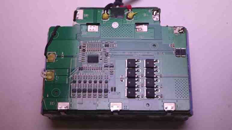
Thankfully this battery pack enclosure was held together with screws, so I could open it up for a look inside. Aha! It is not a raw package of 14 cells in 7S2P configuration, they are under care of a battery management system (BMS) board. Similar to the 3S BMS board I had played with, but this one handles 7S cells. There are spot-welded tabs to monitor voltage of each 2P group. Some of those spot welds are… not textbook, let’s say. But they have continuity and they let me measure voltage. The situation looks even better here. Each 2P group (B- to B1, B1 to B2, etc. through B6 to B+) ranged from 1.1V to 1.9V. The pack as a whole is actually hovering around 10V across its “B+” and “B-” terminals. This is still over-discharged but in far better shape than 3V I measured across output terminals. (P+ and P-)

While the BMS chip is designed to allow charging across P+ and P- terminals, a over-discharged battery is outside of its normal operating range. For reasons I don’t understand, this chip is cutting in and out as I tried to charge with gentle low amperage. The chip may be taking deliberate action to work with over-discharged cells, but it may be getting confused by either the low voltage or my low amperage. There’s a chance the chip’s algorithm is confused and is on a path to destroy itself, the battery cells, or both.

I decided not to trust the chip and go with what I know: steady charge at a gentle low rate. With the pack open, I could connect my bench power supply directly to B+ and B- terminals. This bypassed the BMS chip and allowed me to slowly bring up voltage across the whole pack. Many hours later, pack voltage was up to its nominal 25.9V and I disconnected my power supply. I left the pack sitting overnight so internal chemistries can take its time balancing everything out. It was left outdoors in a bucket, just in case the chemistry decided to get angry. The next day I was happy to see it did not burst into flames. I put it back into the scooter. Now the scooter was willing to power up, and was also willing to take power from its charging adapter. I think we are back in business.

Mama And Baby Bird

A tree in my yard has grown tall enough to approach some overhead wires, so I started trimming it back. A few weeks ago I climbed my ladder and a bird I hadn’t noticed took off. The takeoff point was less than a meter from my face so it was startling. I thought “oh, a bird, OK” and went about my business. It didn’t occur to me to think about the fact local birds usually keep much greater distance.

The next day I climbed the ladder to continue trimming, and was startled again by a nearby bird. Once may have been a random bird that happened to perch on a tree, twice in the same place is not a coincidence. I looked closer and finally noticed a nest with an egg within. Oh no, I had interrupted a very important project!

Mama bird had stayed with her well-camouflaged nest as long as she could, but when I got within arm’s reach it was too much for her. That’s why she took off so close to my face. Sadly, my trimming meant her nest wasn’t as well camouflaged as it used to be. I couldn’t exactly glue those branches back on, but I could pause my trimming until she finishes her project.

I’ve read that some prospective mother birds would abandon a nest if it proved too dangerous, and I was worried it might happen here. Next day I was happy to see she had returned, now that I know where to look and know to keep my distance. I pulled out my big zoom lens and took this picture from 5-6 meters away.

Over the following weeks I checked in on mama bird daily. She was not happy with my tree trimming and erected additional camouflage to mitigate my damage. That made it more difficult to see her but hopefully provided some protection against predators. I hadn’t trimmed the tallest branches yet so she still had decent overhead coverage against other birds, but I was worried about cats in the neighborhood who could now better see the nest from ground level.

Due to mama bird’s new additions and the fact I kept my distance, it was hard to know if her project was progressing. Her perch position seem to change as time went on, but I couldn’t see anything definitive. Besides, if that egg had hatched, it would make sense for her to sit shielding her baby from the exposed side of the nest.

But eventually I saw baby bird sitting on the “dangerous” side of the house, prompting me to pull out my camera equipment again for this family photo. Less than a week after this picture, my daily check of the nest found it empty. It remained empty every day for a week. I hope the family voluntarily moved on to a safer home, but I will never know for sure. Either way, they’re gone now so I resumed trimming my tree.


Less Enthusiasm For Car Projects

I had some project ideas for my 2004 Mazda RX-8 that involved tapping power from its auto-dimming rear view mirror. After determining its power connector pinout, I realized I wasn’t excited to keep going. This marks the end of a chain of events that started with a puddle of coolant demanding my attention to find the leak. I think I’m done with car projects for a bit. I’m writing down my current thoughts which may or may not hold up in the future with more hindsight wisdom.

A big part of keeping an old car running is replacing or repairing old worn out parts. As a car of early 2000s vintage, my RX-8 has lots of plastic and rubber pieces that have become brittle and fragile with age such as the radiator I just replaced. Paradoxically, much older cars may be easier to keep running because more of their parts were made of metal. It’s not very satisfying to replace plastic and rubber pieces that were only designed to survive duration of the warranty.

I did learn quite a few things as I worked my way to the radiator, understanding more of what’s under the hood. I now recognize hoses not just between the engine and radiator, I also recognize hoses leading to the coolant reservoir and leading back towards the interior heater core. This is similar to the thrill I get from teardowns, but that thrill is diminished by many annoyances. The first is that age throws barriers in my way — like stubborn hoses — that are not illuminating and not fun to solve. The second is that, unlike most of my teardown projects, I have to put this thing back together afterwards!

21st century cars also tend to be very cramped under the hood, making everything hard to access compared to the relative wide open spaces under the hood of something from the 1960s. So many sensors, wires, and hoses are packed in there and every single one is a potential point of failure. Parts availability dry up as cars get older, but this problem is worse for low volume cars like a RX-8. Parts are expensive when they are available at all. This is a problem shared with most cars that date back to the 1960s, the difference is that it’s much easier to design and fabricate a substitute. For a 1960s car, it’s likely something mechanical that can be built in a home workshop. For a 2004 car, good luck fabricating a replacement sensor that can keep the engine control unit (ECU) happy. And there’s a risk of such a project going sour killing the ECU, which would turn a small problem into a huge one.

Some people work on their cars to make it uniquely their own and feel a connection to it. I can certainly understand that and I’ve played around with it myself. But projects like retrofitting Android Auto and a backup camera aren’t breaking any ground. (New cars just come with that stuff now.) Neither is a dashcam, so I don’t think it’s going to happen.

Compensating For Lower Radiator Hose Mismatch

I’ve managed to replace the radiator in my 2004 Mazda RX-8, and now I have to put everything back together starting with new engine radiator hoses. Just like with the radiator, I did a quick comparison of old and new before installation and I’m really glad I did.

Cars typically have two hoses between engine and radiator, a RX-8 has three. Its top hose is divided into two parts joined by a metal mid pipe visible in the top left of this picture. The new upper front hose looks pretty close to the old one.

The new upper rear hose looks pretty close as well.

And this is where doing the comparison paid off: the lower hose is not an exact match. It looks pretty good on the engine side (left in this picture) but I see problems beyond that. The hose curvature is different but probably close enough to be bent into shape. The next two problems might be related: First, the radiator-side outlet flares out to roughly 5mm larger diameter than it should be, more than what the hose clamps can compensate for. Second, the flared section added overall length of the hose making it too long. I did a loose trial fit and jamming a too-long hose in place would cause unacceptable kinks in the hose.

Maybe it was a packing error? I double checked part number on the label (Continental 61098) and verified it was the intended product to fit my car. My next hypothesis is a manufacturing error. Somehow this hose wasn’t bent to the exact curvature and the radiator end was not trimmed to the correct diameter and length. The good news is that it’s a lot easier to cut a hose shorter than it is to cut a hose longer. I can fix it now rather than return this item and wait for a replacement to be shipped. I trimmed off the flared end so both the length and diameter is correct for a secure and kink-free fit against the lower radiator fitting.

The final challenge is compensating for curvature. The flawed shape wants to rub up against a sharp corner on the mid pipe bracket. That would quickly cut a hose open and not acceptable.

Fortunately Mazda engineers designed a white plastic clamp that clips between hose and mid pipe bracket so the lower hose is properly routed to avoid damage. Success!

RX-8 Radiator Replacement Route: Above or Below? I Say Both!

I’ve been working my way to the radiator in my 2004 Mazda RX-8, which is buried pretty deep in its nose and set at an angle. It’s been a production to get to it for replacement. Once I removed the engine radiator hoses (which I will also replace) I have removed everything explicitly called out in the workshop manual. That manual called for removing the radiator with the cooling fan module still attached, but it didn’t explicitly say whether the assembly should be lifted up out of the engine bay or dropped down below it. People on RX-8 Club forums have reported success in both directions.

Either choice requires careful maneuvering. Lifting up means I have to be careful not to damage large stubborn wiring harnesses and refrigerant lines for air conditioning. Dropping down means being careful not to damage the air conditioning condenser dangling by refrigerant lines. The radiator’s protruding top mounting brackets are especially dangerous to condenser fins.

I first tried lifting the radiator up but got tangled up between refrigerant lines and wire harnesses. I then tried going the other direction and had better luck carefully lowering it below the car onto the floor.

I removed the fan module and found several pieces of debris that has fallen in there over the life of this car. The largest piece was a rubber bushing that I didn’t immediately recognize. I would later figure out it was part of the cosmetic engine cover. I lost both bushings over the years and my engine cover could only sit loosely in its position. Now that I’ve recovered one bushing I could reinstall the cover more firmly when I care to do so.

Some of the debris bounced around fan blades before settling down off in a corner. The old radiator on the left showed two arcs of damaged fins that lines up with the lower edge of fan blades. I set the replacement radiator down to the right for a quick side-by-side comparison to verify it looks largely correct. All the hose fittings seem to be the same diameter and located in the same places, as are all the attachment points for the fan assembly, the AC condenser, and chassis structure.

Transferring the fan assembly and mounting hardware, I had a new radiator assembly to install. I tried to reverse what I did earlier but had trouble lifting the assembly from the ground into the engine bay. This assembly is not heavy, but lifting it means bending over the front of the car and reaching through the engine bay out the bottom. It was an awkward pose with poor lifting leverage.

Next I tried to drop the assembly in from the top, but the same wire harness and refrigerant lines were in the way. This time I got smarter: I rotated the assembly 90 degrees so I could lead with the narrow side edge of the radiator, and that allowed me to clear refrigerant lines and wires. Once the leading edge is poking down under the car, I carefully rotated the radiator back into proper orientation.

So my opinion for the top route vs. bottom route discussion is: both! I think it’s easier to let gravity help instead of fighting gravity. Which means removing old radiator out the bottom, then install new radiator from the top. This is especially true for someone working solo as I did. If there are more hands available, it should be easier to maneuver the assembly and lift against gravity so a different path may work better when installed by a team.

With the new radiator in place, I moved on to installing new radiator hoses and promptly hit my next problem.

Peeling Old Radiator Hoses Off Fitting

I’ve learned that the radiator in my 2004 Mazda RX-8 was long overdue for replacement. Conventional wisdom says if a radiator is getting replaced due to age-related issues, it’s a good idea to replace hoses at the same time. Partly because they are flexible parts subject to wear from age, and partly because we have to remove one end anyway during radiator replacement. I added hoses to my radiator order.

First lesson: my locking pliers are my allies when battling hose clamps.

Second lesson: radiator hoses that have been clamped to the same fittings for over twenty years are reluctant to move. Once I freed the hose clamp, radiator-side hoses came loose with a hard tug. But the engine-side fittings were more challenging. It took far more effort to remove the top radiator hose and, once freed, I could see the problem: a layer of buildup acted as glue between hose and fitting. I think most of this is dried coolant, but some of it may be corrosion. Most of it crumbled when I scraped with my fingernail which I then wiped away.

The engine’s lower radiator hose is buried deeper. I chose to remove the secondary air injection pump to give myself more elbow room but I still couldn’t pull the hose free. Again I exercised my dial-an-expert option and Emily Velasco suggested working a screwdriver in there to free up the hose. This makes sense: I’m pulling parallel to the adhesion surface, the direction where it is strongest. I need to apply force perpendicular to the adhesion surface, like how we peel off a piece of adhesive tape.

However, tight quarters meant I couldn’t get a tool in there, but Emily had a simple solution: bend a screwdriver. I chose a small one that was bundled with my Creality Ender 2 and bent it into a tiny little pry bar. Now I could push the tip into the gap between old hose and engine fitting, and I could hear and feel the tactile sensation of those surfaces peeling apart.

Once the adhesive bond between hose and fitting was broken, I could pull these old hoses free clearing the way for radiator removal.

Old RX-8 Radiator Was About To Fail Anyway

I decided to go ahead and install a replacement radiator in my 2004 Mazda RX-8 despite the fact it arrived with some minor damage presumably in shipping. I’ve temporarily patched my old radiator but I expected it to fail again soon given its age. This turned out to be a good call! As I started preparing to move the coolant reservoir tank out of the way, its associated radiator fitting broke off.

I learned from RX-8 Club forums this fitting becoming fragile with age is a known common problem, but I was surprised at how little effort was involved. I estimate it took less force than what it would take to break a piece off a chocolate bar. I might have been one bad pothole bump away from this thing breaking on me. In fact, looking at the pattern of dried residue around the break, it was already degraded enough to seep coolant for some time.

My next problem was how to extract its remnants from the hose. Consulting my friend Emily Velasco’s experience of working with old machinery, she expected this segment to be just as fragile as the rest. A firm squeeze with some big pliers should be enough to break this apart into smaller pieces for extraction.

Her expectation was correct, it didn’t even take much of a squeeze for the thing to fall apart. I had expected to feel some resistance or maybe a “snap” marking the point of breakage, but there was nothing. I squeezed and it collapsed. I pulled out the pieces and tried squeezing the hose again with my pliers. The effort level was basically the same.

I picked up one of the pieces and tried pushing it with my finger. I was able to fold it in half with about as much effort as a graham cracker. Yikes. This thing is long gone.

And that’s not the only thing showing severe degradation. Here’s a picture I took of the top engine hose fitting after I removed the radiator. It showed discoloration and material degradation similar to the snapped-off reservoir hose fitting. The worst discoloration corresponded to where the hose clamp applied pressure. The base of this fitting was where I found a crack (and applied J-B Weld) and it’s pretty obvious that crack was merely the first clear failure and many other potential failures were close behind.

Bottom line: Yes, replacing the radiator was a good idea! And with these broken fittings, I’m past the point of no return. The car is not going to drive under its own power again until the new radiator is installed. Next step: struggling with old radiator hoses.

Replacement RX-8 Radiator Arrived Slightly Damaged

I ordered a replacement radiator and associated hoses for my 2004 Mazda RX-8 before I found out my engine is terminally ill. I briefly contemplated not bothering with the radiator but then I decided to look on the bright side: If the engine is on its way out anyway, it doesn’t matter as much if I screw things up. I can dive into the learning experience of performing my own radiator replacement with less pressure. So far I’ve done oil changes, brake pad replacements, ignition system upgrade from Black Halo Racing, and replaced a water pump that had started weeping coolant. A radiator replacement seems like an appropriate next step up in difficulty.

After the radiator arrived I opened the shipping box and was mildly disappointed to see radiator fin damage both front and back. The radiator had fallen off of its packing foam blocks and the air pillows fell out of place. I wished they had taped the foam and pillow to the radiator instead of loosely draping. Inspecting the radiator, I saw no other signs of damage. All mounting points seem intact and accounted for, and all three hose fittings appear to be in good shape. The smallest and most fragile fitting for coolant reservoir connection even got a separate protective rubber boot!

Besides, the fin damage is pretty trivial compared to visible condition on my remaining heat exchange units: the air conditioning condenser in the middle and oil coolers on either side. Their fins are pretty bent up from twenty years of road debris, and they’re still sufficient. Besides, as a clumsy beginner, I think it’s pretty likely I’d bend a few radiator fins as I try to install it. If this radiator is not going to stay pristine for long anyway, why worry about a few bent fins now? It will have enough cooling capacity to keep the engine from overheating. And if I’m wrong… well, the engine was on its way out anyway. I’m going to jump in with an enthusiasm for learning.

Problems Of A Mazda RX-8 With Low Compression

My 2004 Mazda RX-8 has failed its compression test. This fact did not come as a huge surprise given its age, but it’s still disappointing news. Long term I will have to either get a rebuilt engine or move on to another car. In the short term I will live with this condition and I’ve been reading up on what to expect going forward from RX-8 Club owners’ forum and sites like RX-8 Help. This post is my summary notes to future self.

Poor compression degrades power output which in turn degrades fuel economy. Beyond that, it is expected to slowly degrade my car’s drivability until I reach limits of my tolerance for frustration. For example, what kicked off this investigation was the fact my car would occasionally stall instead of idle. This symptom will get worse. Increasing in frequency from “occasionally stall” to “frequently stall” and my patience will run out somewhere along that spectrum.

Low compression can also make “hot start” difficult: Unable to start an engine when it has already been warmed up and things are hot under the hood. Most commonly noticed at short stops such as when stopping off at a gas station. (… or when the engine stalls at idle…) I’ve noticed my starter motor cranking an extra second or two before the engine catches but so far it has always started. As compression degrades, it’ll take longer and longer until at some point it just won’t catch and I have to let the engine bay cool down before I can start the engine. Not a big deal if I’m sitting in a parking spot, but if I’m at a gas station I will have to push my car out of the way so other people can refuel. If this happens I will be highly motivated to act on one of my long term options.

Increased workload on the starter motor may burn it out. I could then replace it with a unit from a later “Series 2” RX-8 which runs faster. Since rotary engine compression improves with speed, a faster motor is more likely to start an engine suffering from bad compression. Some aftermarket starter motors can give me this effect as well. A faster starter is only a workaround that delays the inevitable, but it is an option if I want to spend a hundred bucks to postpone a far more expensive decision.

How long might I have before encountering such drivability issues? That is unfortunately murky. Poor compression means some of the air+fuel mixture, either before or after combustion, are escaping past one or more worn seals. The exact escape route will vary from engine to engine because every one wears out slightly differently. It is possible for certain escape routes to cause erosion that starts a destructive feedback cycle of engine wear. In which case my car’s gradual descent becomes a nosedive.

Speaking of escape routes: if some of that mixture leak past side seals, they would end up in engine oil. Such an increase in oil contamination will demand frequent oil changes in order to avoid triggering bad oil problems. I’ve done oil changes every 3k miles for as long as I’ve owned this car and this is one more reason not to slack off now.

And finally, the catalytic converter might get caught up in the aftermath. Even in a healthy engine, some small amount of fuel would escape unburned out the exhaust port. The catalytic converter exists to catch those molecules and convert the nastiest bits to less-bad compounds. But if unburned fuel is leaking past worn seals, the catalytic converter may receive more than it can safely handle and fail. Usually catalytic converter failure would illuminate my Check Engine light and the car would fail regular state-mandated emissions test. In the rare case, though, it is possible for an overloaded catalytic converter to catch on fire. At some level I admire a car that decides to go out in a blaze of glory, but that’s not the kind of excitement I want in my life.

For better or worse, none of these things demand immediate attention and I can still drive my car as-is for an unknown period of time. Which means I should get back to my project to-do list now that the replacement radiator has arrived.

Mazda RX-8 Compression Tested Low

I replaced battery terminals in my 2004 Mazda RX-8 because they were corroded and poor electrical continuity might have caused the occasional engine stall at idle. The new terminals look great, but my engine would still stall, so I investigated other possibilities listed in the workshop manual and found a likely explanation: my engine is very low on compression.

A compression test was one of the listed diagnostic items but not something I could do myself. While some auto part stores offer engine compression tester rental, they’re for piston engines. Rotary engines require a specialized testing tool. The service department of my nearest Mazda dealership doesn’t have theirs anymore so I searched for a local rotary engine specialist shop. I found Lucky 7 Racing offers rotary compression testing and took my car to their new City of Industry location.

A rotary engine tester measures pressure value for each chamber around the three-sided rotor and also engine RPM. The nature of a rotary engine means compression pressure rises with RPM. (Oversimplified explanation: centrifugal force flings apex seals outward against the housing, improving compression as it spins faster.) So the tester also normalize/compensate its readings to 250 RPM for comparison purposes. According to “Compression Inspection” section of Mazda’s workshop manual, standard compensated pressure is 830 kPa and minimum acceptable value is 680 kPa. For my engine, compensated pressure values for one rotor measured 581, 556, and 554 kPa which are well below minimum. The other rotor measured 393, 392, and 347 kPa which aren’t just below minimum, they’re less than half of standard pressure! My engine is in sorry shape.

Low compression is a common symptom of old engines as various parts wear down. For a piston engine, valves and piston rings are the usual suspects. For a rotary engine, their apex seals are usually the first things to go. Dropping below 680 kPa is cause for engine replacement under Mazda warranty but since the powertrain warranty has long since expired, this is now entirely my problem.

A new engine is not an option, Mazda production wound down years ago. A proper fix now means taking the engine apart to replace worn out bits. Lucky 7 Racing performs rotary engine rebuilds, but that is typically done for performance-focused customers who want to install more durable (and expensive) race parts to wring out maximum power. For a daily driver car like mine, its faster and easier to swap my engine core with another core that has been remanufactured at a dedicated facility. Either option will be significantly more expensive than the market value for a 2004 Mazda RX-8. In other words, it would cost more than I could possibly ever get back and makes no financial sense. Plenty of people are passionate enough about their rotary-engined cars to pour money into a hole, keeping shops like Lucky 7 busy. I will have to decide if I’m one of them. Until I make that decision, though, I will have to live with the problem.


Header image: “Rotary Man” sculpture sitting among parts and equipment at Lucky 7 Racing. His head (painted blue) is a rotor and his torso (painted white) is an eccentric shaft.

RX-8 Battery Terminal Replacement

After installing a backup camera for my 2004 Mazda RX-8, I wanted to look into an engine stall problem I’ve been having. As I approach a stop sign or red light and release the throttle pedal, engine speed will drop as expected. Usually it’ll settle at idle speed, but every once in a while the engine would drop all the way to zero RPM and I would have to restart the engine… which sometimes would stop again immediately unless I use a bit of throttle to keep it at a higher RPM.

According to the workshop manual, there are many potential explanations for this symptom. The cheapest and easiest thing to check is my battery connection. I guess the alternator doesn’t provide enough power at idle so the battery needs to pitch in?

Well, my battery terminals are pretty old. There have been several batteries throughout the car’s 20+ year life and a few of them have leaked battery acid to corrode these terminals. The plating is long gone, and some of the core metal has been eaten away as well. They are due for replacement whether they are causing this problem or not.

I first tried a set of “universal” terminals from AutoZone. I think they probably suffice from an electric continuity standpoint, but they are a little bit longer than the previous units.

For the positive terminal, they’re too long for the protective cover to close. For the negative terminal, the extra length pushed wires against the battery strap and I worry about abrading wire insulation. I don’t think these are going to work well long term.

Now that I have learned length can be an issue, I measured length of the old terminal and found these units on Amazon with the correct length. (*) I confirmed the length with a quick test fit, but the test fit found another problem: they are too loose to clamp tightly on my battery posts.

To solve this problem, I cut away the center red plastic tongue to give it more room to clamp down. I used the cut-off piece of plastic as nut washer/spacer so my socket wrench could grasp the hex nut for a properly tight fit.

Once installed, these terminals appear to give me the same fit as the earlier units. The negative terminal no longer pushes wires against the battery strap.

And now the positive terminal protective cover closes properly.

I’m happy I fixed this particular eyesore under the hood, but soon after this swap, my engine stalled again. Old corroded battery terminals weren’t the cause, so I need to continue working down the workshop manual’s checklist of potential causes.


(*) Disclosure: As an Amazon Associate I earn from qualifying purchases.

RX-8 Backup Camera Bracket

I’ve decided to retrofit a backup camera to my 2004 Mazda RX-8. After running the camera wire from the dashboard receiver into the trunk, I had to install the camera somewhere and plug into that wire. I decided to put the camera near my rear license plate, which meant I had to remove many old brittle plastic fasteners before I could remove my rear bumper cover. I was happy to find I didn’t need to drill any holes in either the body or the bumper cover. There’s a slot already in the bumper cover to accommodate a license plate light, and it’s much wider than it had to be. The metal body had several existing holes I could repurpose for my project. I removed an existing plastic-and-rubber plug to run my camera wire, followed by a dab of hot glue to plug it up so rain water does not enter.

That leaves the problem of exactly where to mount the camera. The bundle came with a license plate bracket that would mount it centered above the license plate, but that would block my license plate light and I doubt law enforcement would be happy about that. It also came with a small bracket and double-sided foam tape but I didn’t trust tape under SoCal summer sun. I had a metal frame around my license plate purely for aesthetics, so I drilled and tapped two M3 holes in the frame corner for the small bracket.

I was so focused on the camera that I didn’t notice what I had done until I took a step back and looked at the situation: the camera now obscures my license plate registration sticker, and that’s going to make local law enforcement even grumpier than if I had blocked the light.

I have a stack of small thin aluminum sheets waiting for a project, and I decided to fashion a mounting bracket from one of them. I don’t have real sheet metal cutters (it’s on my tool shopping list) but this aluminum is barely thicker than kitchen foil and easily cut with diagonal cutters.

A test fit looks good, tucking the camera into the existing slot adjacent to the license plate light so I don’t block the light.

Now the camera draws less attention and it doesn’t block my registration sticker either. Looks great, I’ll keep an eye to see how well it holds up long term. Onward to the next project.

RX-8 Navigation Upgrade Project Phase Two: Backup Camera

My 2004 Mazda RX-8 has a cracked radiator. While I wait for a replacement radiator to be shipped to me, I’ve applied some J-B Weld as a short term workaround. And since I already have tools scattered about my garage, I thought I would work on a few more RX-8 project to-do items. First on the list is I will resume my navigation screen upgrade project. I had removed the stock GPS navigation system LCD screen and replaced it with a standalone receiver for wireless Android Auto/CarPlay. My receiver came bundled with a backup camera, but I decided against tearing up too much of the car before I decided if I even like the receiver. So I paused after receiver installation to evaluate.

It’s been a few months and the inexpensive receiver has not been perfect. I have to manually adjust screen brightness between daylight and night time driving, but that’s only 3 taps and a mild annoyance I can live with. I’ve had the occasional audio stutter and data dropout, reminding me why wired connections are always more reliable than wireless. Sadly wired Android Auto/CarPlay have fallen out of favor with standalone receivers like these. I’ve also seen the thing crash and reboot itself, but not often enough for me to recognize any pattern to what might have trigger it.

Despite its imperfections, I have grown fond of having my phone automatically connect to my car every time I start it up. It’s nice to always have Google Maps on screen and access to my entire audio entertainment library stored on my phone. Given its low price ($60 as of this writing *) I can forgive a few hiccups here and there. It’s a keeper! I will now proceed to install that backup camera which had merely been gathering dust the past few months.

Accessing the stock factory navigation display hood is a lot easier the second time around. I now know enough to avoid completely disassembling the center console like I did the first time. For example, now that I know I only need to access two fasteners behind the factory audio head unit’s face plate, I only need to slide it out a few centimeters leaving all wire bundles connected. Much easier this way!

After plugging the camera cable into the receiver, I ran its wire down the left side of the center console. Under the ashtray and along the center of the car underneath all cupholders. I mostly followed the existing navigation computer wiring harness. Speaking of which, I took this opportunity to unplug all connectors from that outdated computer so it doesn’t consume power uselessly. I thought about removing it entirely but I didn’t want to leave a hole in the console between rear seats. The backup camera cable proceeded under the now-unplugged computer, behind the right rear passenger seat back, and into the trunk where it can meet up with the camera module. That takes care of the electrical wiring, now I need a camera mounting bracket.


(*) Disclosure: As an Amazon Associate I earn from qualifying purchases.

Temporary Radiator Fix Using JB Weld

I noticed a coolant leak on my 2004 Mazda RX-8 and tracked it down to a cracked radiator housing. The good news is I think I caught this problem before it caused any serious problems, the bad news is that it’s hard to get parts for a low volume car that’s over 20 years old. I had no luck finding a (reasonably priced) replacement radiator locally, so I ordering one to be shipped to me.

What do I do in the meantime? I suppose I could continue driving the car, frequently topping off the coolant reservoir with water. I don’t think that’s a good way to go, though, because hot pressurized liquids have a history of making small cracks bigger. Possibly turning this radiator failure into an overheated engine failure. So I decided to try plugging the leak with some J-B Weld. I learned of this miraculous product from watching 24 Hours of LeMons video summaries, helping many teams get their car back out on the track.

This will be my first opportunity to use the product myself, and a great practice opportunity! Since I plan to replace the radiator soon, it won’t really matter how well the product works. But I will gain the experience of using it, and a short period of seeing it in action. For some guidance I enlisted my friend Emily Velasco who has J-B Weld experience and here’s what we did:

For surface prep, the surface around the crack was cleaned up and sanded down to give the epoxy a rougher surface to grip on to. The coolant level was drained below the height of the crack so it would quit weeping out which would interfere with epoxy adhesion. Once the area was clean, roughed, and dry, the first batch of J-B weld was mixed and applied.

For patch jobs like this, Emily recommends putting in something to help add structure to the blob of epoxy. A thin sheet of metal is common, and I remember seeing LeMons racers cutting up old license plates for this role. Unfortunately, we are dealing with a compound curve here so bending a sheet of metal to shape is difficult. As a workaround, our Home Depot run involved picking up a sheet of fiberglass cloth (Bondo 20128) along with J-B Weld. Emily recommended using the original formula and not the quick-cure type I saw in LeMons videos, because unlike them I am not in any pressure to get back out on the track.

A small square of fiberglass cloth was cut out and pushed into the still-soft first layer of J-B Weld. After the first layer had set (4-6 hours) but before it cured (15-24 hours) a second batch was mixed and applied on top. The result is not pretty, but it held well enough to stop further coolant leaks. The awkward position of the crack meant we got some J-B weld on adjacent components though I don’t think they’ll get in the way of future radiator replacement. I hope this old radiator’s brittle plastic doesn’t crack somewhere else while replacement radiator is still in shipping.

While I wait on arrival of that radiator, I decided to tackle other RX-8 projects on the to-do list starting with installing a backup camera.

Tracing Mazda RX-8 Coolant Leak to Cracked Radiator

I bought a pack of commodity 8mm plastic fasteners so I could replace old and brittle fasteners on my 2004 Mazda RX-8. I knew there were a lot of them holding the front bumper cover in place, fastened to wheel well liners and other adjacent pieces. And I knew I would have to deal with them because I noticed a puddle of coolant under the car when it is parked. There is a leak I have to track down!

The radiator is tilted forward roughly 45 degrees so the top edge is ahead of the bottom edge. Immediately above one side of the radiator is a coolant reservoir tank. From this pair, several hoses large and small lead backwards to the engine and cabin heater core. Given this knowledge, I was mystified by my observation coolant is dripping from somewhere in front of the radiator. I don’t understand how coolant got so far up front, but to get a closer look I need to remove the front bumper cover and several airflow management panels directing air through the radiator. About a dozen of those 8mm plastic fasteners later, I can get a clear look at the air conditioning condenser and the radiator immediately behind it.

Given the car’s age, I had expected to find coolant leaking from an old cracked radiator hose. It’s a common failure point and inexpensive to fix. But the forward drip location made me suspicious that might not be the case. Tracing dripping coolant back to the source, I found the leak and it was indeed not a failed hose.

The top of the radiator has cracked between two hose fittings, near the base of a hose fitting leading to the engine. The failure point is very inconveniently positioned for picture-taking. This is the best I can do, which required removing the battery and engine air filter box, and even then I know this picture lacks context.

Here’s an annotated version which might help. The camera is in the engine compartment looking roughly forward-right, but tilted at an angle. I have two arrows labeled UP and FRONT to designate those orientations. The crack is still very small and when the engine is cold, barely any coolant dribbles out flowing down the front of the radiator. However, when the engine is hot and cooling system is pressurized, a very thin stream of coolant shoots out of the crack towards the front. This stream will strike a piece of chassis metal ~10cm away before falling and that is why I saw coolant dripping in front of the radiator.

I’m glad I caught this problem before erosion expanded the crack big enough to drain all coolant and cause an engine overheat. I believe this is the original 20+ year old radiator. While the radiator core is made of aluminum cooling channels and fins, the top and bottom caps are made of plastic. Searching through RX-8 owner forums, old radiators cracking their brittle plastic is a known failure. Radiator replacement is the correct fix. Patching the crack will only be a short term fix because that old brittle plastic will fail somewhere else soon enough.

Commodity Plastic Fasteners (8mm Diameter)

I have several projects on the to-do list for my 2004 Mazda RX-8, but I had been procrastinating because I hated dealing with its plastic fasteners. These are designed to fit in holes roughly 8mm in diameter and hold two or more pieces together. Usually at least one of those pieces is a flexible body trim panel.

They are made from two pieces: an center portion that pushes against the outer portion so the latter expands to hold the fastener in place.

Here’s what the head looks like in the fastened state.

In theory, we release this fastener by a quarter-turn of a Philips-head screwdriver.

This pushes a few wedges/ramps against each other and pops the center free, allowing the outer portion to contract and letting us pull the fastener out of its hole.

In practice, years of road dirt and grime jams up the works so the center doesn’t want to turn. Applying more torque risks stripping the slot, and the typical technique to avoid cam-out is to push my screwdriver harder inward. This force directly defeats the purpose of the turn, which is to pop the center outward! I’ve always felt it was a bad design to put such forces in direct opposition to each other. Despite my efforts to avoid damage I would end up stripping the inner slot and have to find some other way to release the fastener. This usually ends up damaging the fastener (this one’s outer ring is cracked) as well as the panels it had fastened to.

I’m not sure if these are factory original Mazda parts, but I do know I have came across multiple different fasteners on my car. Some of them might have been fitted by mechanics who have worked on my car over the past two decades. I understand why they would perform such substitution, and I will follow their lead.

My criteria was to find something advertised for 8mm holes and suited for outdoor environment applications. These are pretty generic commodity parts used across multiple industries for different purposes, but there doesn’t seem to be a commonly agreed upon name for these things. I settled on an Amazon product that just incorporated a bunch of different words into its lengthy title: 200PCS 8mm UTV ATV Fender Push Clips with Fastener Removal Tool, Nylon Body Rivets Fasteners Clips Compatible with Polaris Ranger RZR Can Am Kawasaki Teryx Honda Suzuki Sportsman (*)

And the best part: this design doesn’t require self-defeating forces to remove. Again this center component is designed to pop out, but this time it’s not the turn of a Philips screwdriver. Instead, this has side slots for me to pry against to pop them out.

On the downside, these lowest-bidder items are definitely not as nicely made, with crude plastic injection molding flash all over. Diameter of the head is not as large as my original fasteners, and length is slightly longer. Despite these differences they seem sufficient due to the loose tolerance nature of the application. They are good enough for today but the real test will come years down the line when I try to release one seized up from years of dirt and grime. I figured even if it doesn’t release, I could take a large pair of diagonal cutters and cut it off. I know how to get plenty of replacements.

Having that option is great, because it greatly eased projects that require dealing with such plastic fasteners. And I already have one on my hands: tracking down a coolant leak.


(*) Disclosure: As an Amazon Associate I earn from qualifying purchases

MX340 Paper Tray Gearbox Details Not Generally Applicable

I’ve been having fun learning how things worked inside my retired Canon Pixma MX340 multi-function inkjet. Some lessons have direct application to personal projects, especially regarding components that I think I can repurpose in the future. Others are more general, like clever mechanical design concepts that I might be able to adapt to a 3D printed future project. Then there are lessons just for the sake of satisfying curiosity. Looking at implementation details of the paper tray sheet feeding mechanism, I’m definitely in the territory of that last category.

Designing this mechanism took skill beyond what I can comprehend today, orders of magnitude more sophisticated than my 3D printed mechanical contraptions. Part of this stems from the fact I haven’t built up the mental skill to organize knowledge of complex mechanical interactions. My software background gave me ways to think about software interactions, organizing them into API layers and partition module interactions into various levels of abstractions. Looking at a mechanical gearbox where forces can be transmitted via multiple paths to the same destination, at gears that only have teeth to transmit power partway through their circumference, at the freewheel element that turns one way but not another… my brain is overwhelmed trying to keep track of all potential interactions.

I think a good analogy is learning a new language. (The human spoken kind, not the computer programming kind.) It takes some experience to learn enough to mentally catalog and partition the sounds we hear. Knowing where one word ended and another began is an important early skill. Knowing what sounds are critical and what sounds are just person-to-person variation is another big step.

At the moment I lack the equivalent skills to understand and analyze what’s going on inside this gearbox. I also lack the motivation to understand designs optimized for mass-production, which I don’t plan on doing. In other words: if I put in the work to understand it all, I would learn some very domain specific knowledge on a cheaply mass produced mechanism to feed the top sheet of a stack of paper. I don’t foresee that knowledge as something useful to me in the near future. The cost/benefit ratio for diving deeper into this gearbox doesn’t look great, so I’m going to stop here.

Still, I’ve learned a lot of interesting things, and I’m confident this exposure will help me understand more of the next mechanical marvel I encounter in a teardown. A process I intend to repeat until that day when I can look at a complex mechanical system and not get overwhelmed. An iterative process starting with admitting that day is not today, allowing me to focus on other lessons I can more easily absorb.


This teardown ran far longer than I originally thought it would. Click here to rewind back to where this adventure started.

Initial Motion Decoder Outputs Look Good

I’m trying to keep an Arduino project’s code simple, which required resigning myself to the fact it won’t be very robust as it decoded paper feed motor motion of a Canon Pixma MX340 multi-function inkjet. I’m at the mercy of a magic threshold value, and the errors it could introduce if it’s too small or too large.

The Arduino sketch is looking at position reported by a quadrature encoder in this gearbox and, if it hasn’t moved in 10 milliseconds (my magic threshold value), print how far it has moved since the last time it stopped someplace for at least 10ms. I’ve also added code to track the shortest time between encoder positions encountered during this interval, which reflects the fastest speed attained.

Before this threshold-triggered report, I would have a long list of numbers that I could import and plot in Excel. Here’s the position & velocity graph for the machine’s startup sequence.

And now, I have a very short list of movements taken and how fast it moved to get there. Here is the startup sequence again in the new format:

timestamp,count,min_us_enc
16,1799,28
13003168,2701,36
13478700,-1800,-28
13622500,-1800,-28
16468560,28020,36
20880704,2700,36
21135412,-2700,-38
21392592,-15000,-68
23213924,1800,28
25595052,-1799,-28
25739804,1798,28
25884356,-1798,-28

Timestamps don’t line up between these two different presentations because they were taken on different sampling runs, but the change in encoder counts and velocity match. This is a far more concise report of motion control behavior, presenting information I wanted and discarding the rest.

One big difference between this output and the goals I had originally set is the lack of reporting on times when the system sat still. I thought it would be useful to know when nothing changed from time X to time Y, but the simple implementation generated noise from small movements and I didn’t come up with an elegant way for it to coexist with my debounce code. I thought about it some more and remembered my goal here is to capture what kind of movements are involved in this gearbox. I don’t really care about the times when it didn’t move, so I deleted all associated code as unnecessary complexity.

We’ll see if that turns out to be the right call or if I will regret not investing the effort to make it work. For now, this decision means a caveat on interpreting my decoded output: timestamps corresponding to each motion includes the time spent sitting still before each motion. Example: the third and forth lines of data both reflect a move of -1800 encoder counts…

13478700,-1800,-28
13622500,-1800,-28

The timestamps are only about 144 milliseconds apart, but looking on the big chart above we can see the actual movements are nearly 3 seconds apart. That’s because the second timestamp here was actually the start of that ~3 second period of staying still, before moving another -1800 encoder counts.

Despite its flaws, I think it’ll be useful enough of a tool to parse the motions I’ve been looking at.


This teardown ran far longer than I originally thought it would. Click here to rewind back to where this adventure started.

Captured CSV and Excel worksheets are included in the companion GitHub repository.

Trying Dwell Time To Delineate One Motion From Another

After fumbling around the edges for a while, I finally got a decent acceleration/deceleration plot of paper feed motor in a Canon Pixma MX340 multi-function inkjet. It was very informative not only in a “satisfy curiosity” way, but also in a “oh, my plan isn’t going to work” way as well. Better I discover the flaw now rather than later!

The challenge is to recognize when one motion has ended and another has begun. My first effort was to sample encoder position as fast as possible and, when there’s zero delta between two samples, declare that a point of delineation. This idea failed spectacularly. So I thought I could base my decision on acceleration: when the motor starts accelerating after a period of deceleration, declare that a point of delineation. But now that I’ve looked at the actual plot, I know that won’t work either. Several changes in acceleration rates occur within a single motion during normal operation, so that is not a reliable indicator to use.

I could withhold decision until acceleration exceeds a certain threshold, but that means I have to track a longer history. Back to when the candidate delineation point existed, so I could output that data when the decision is made. I’d like to avoid adding such runtime data management complexity. On top of that, it would add a threshold setting problem into the mix.

If a threshold setting problem is inevitable, I might as well try it in the context of something simpler with less data to manage: dwell time. Defined as: how much time the system spends sitting at a particular encoder position. This is similar to the earlier “zero delta between two samples” approach, but now based on microsecond timestamp rather than an unpredictable “time elapsed between polls by loop().” Looking over the data I captured of system startup, I see “not quite there yet, need a little kick” dwell times of a little over 9000 microseconds. Given that, I’ll start with a dwell time of 10000 microseconds (10 milliseconds).

I think it’s better to have this threshold a little too low versus too high. When it is too low, it would falsely break up a single motion. For example, “Moved 1798” then “moved 2” instead of desired “moved 1800”. This will add noise to the motion decode output, but I think it is the lesser evil. Setting it too high would falsely combine multiple motions into one: “Moved 900” instead of “Moved 2700” and “Moved -1800” and such mistakes would be more difficult for me to recognize when looking at motion decode output.


This teardown ran far longer than I originally thought it would. Click here to rewind back to where this adventure started.

Captured CSV and Excel worksheets are included in the companion GitHub repository.

MX340 Paper Feed Motor Acceleration/Deceleration

I’m working to interpret quadrature decoder positions reported for the paper feed motor of a Canon Pixma MX340 multi-function inkjet. I was happy a relatively simple debounce filter cleaned up a lot of the noise introduced by small encoder movements, but I was still having a hard time interpreting the results. I knew this would be a problem when I chose to log “microseconds per encoder count”. It was the reciprocal of the more obvious “encoder count per microsecond” velocity. I chose it to keep computation in the integer realm, avoiding floating point math. It should help keep the ATmega328 microcontroller in my Arduino Nano fast and responsive, with the tradeoff of causing me headaches now in analysis.

After squinting at this for a while, I realized I was being silly. I’m looking at the data after the fact, I no longer have to concern myself with keeping code fast and responsive. Furthermore, I’m now on a desktop computer whose CPU had floating point capabilities the ATmega328 lacked. I added a new column in Excel, with the simple formula of 1 divided by us/enc, and graphed resulting enc/us as my orange line.

Beautiful! Now the graph is a lot easier for me to grasp at an intuitive level. It’s easy to see motions for this startup sequence occur at several different peak velocities, and it even showed an artifact I wanted to investigate further: little velocity spikes book-ended some of these movements. (Might not be visible at blog resolution here. There’s a zoomed-in version below.)

When skimming through the raw us/enc data, I noticed the change in velocity was not uniform.

[...]
2963072,4484,1,992
2964064,4485,1,980
2965044,4486,28,1448
2966492,4487,27,1428

2967920,4488,1,1052
2968972,4489,1,1076
2970048,4490,1,1024
2971072,4491,1,1024
2972096,4492,14,1248
2973344,4493,130,3148
2976492,4494,324,6376
2982868,4495,88,2564
2985432,4496,18,1408
2986840,4497,5,1132
2987972,4498,3,1108
2989080,4499,1,1016
2990096,4500,952,[...]

This excerpt was from second movement decelerating towards its final position of 4500. From a peak speed where only about 65 microseconds were spent at each encoder position, this excerpt started when we’re slowed enough to spend almost 1000 microseconds (1 millisecond) at each position. Position 4486-4487 each got around 1400us, then the system sped up. Then it slowed down towards position 4494. Over 6 milliseconds were spent there, then we see a final kick to bring it to position 4500.

Zooming in to the velocity plot of first three movements, I can see this “not quite there… little more power… not quite there… more power” as a bit of saw tooth shape at the end of each deceleration curve. This graph also showed me something I hadn’t noticed earlier: a similar saw tooth at the beginning of the second and third movements. They started moving with a sharp acceleration that was then dialed back before reaching their target velocity.

What might this mean? I speculate movements started with extra power in order to overcome static friction in the system. Once things started turning, the closed-loop motor control algorithm reevaluated power levels to maintain target acceleration on its way to target velocity. Then for deceleration, the control algorithm might deliberately aim for a slight undershoot, adding little bursts of power towards the end to reach target position. Aiming for a slight undershoot makes sense to me. If it had overshot, correction would have had to deal with gear backlash and reversing the inertia of the entire system, a much bigger can of worms.

Whatever the reason, the fact is acceleration/deceleration rates varied within a single movement, something easily visible once I actually plotted velocity vs. position. It’s a pretty cool discovery even though it invalidated a plan I had.


This teardown ran far longer than I originally thought it would. Click here to rewind back to where this adventure started.

Captured CSV and Excel worksheets are included in the companion GitHub repository.