Acrylic Lights: Infinity Mirror

I’ve played with putting lights in my 3D-printed creations for glowing illumination effects. There were limits to what I could do with 3D printing, though, because printing with a clear filament does not result in a clear object. In contrast, acrylic is clear and works as a light guide with a lot of possibilities.

I’ve noticed a few attention-getting light effects in my acrylic projects to date, most of them created by happy accident. The acrylic box with external fixture made good use of external light. The Portable External Monitor version 2.0 was built from stacks of acrylic sheets: its fluorescent back light reflected between the layers like an infinity mirror.

PEMv2_InfLights

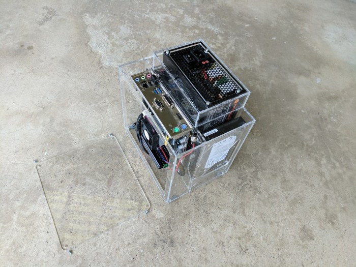
This effect was on my exploration to-do list for the future, but I moved it to the top of the list after seeing surprisingly good results on the FreeNAS Box v2 enclosure.

I had planned for it to have the standard PC status LEDs: one for power, and one for disk activity. The acrylic plate for motherboard mounting spacer also had two cutouts for 3mm LEDs along the center line. The red hard drive activity light is to be mounted high, and the blue power light mounted down low. The idea was for the blue light to illuminate the top edge of the plate. When there is hard drive activity, red LED will light up the center of that edge, and it should blend to purple with the power light. Both LEDs were blocked from direct view by the motherboard, so all we should see is a nice soft glow emitting from behind the motherboard.

FreeNASv2LightPlan

That was the plan, the reality was different. The red activity light worked as expected: when there is disk activity, the center of the top edge had a little red glow.

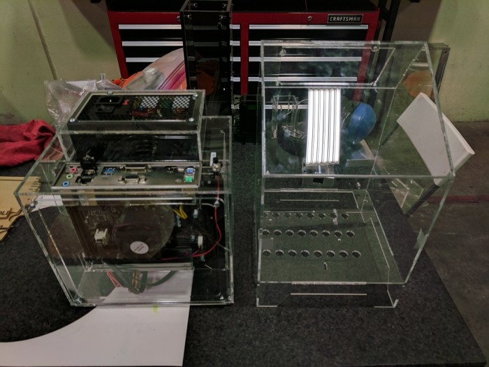
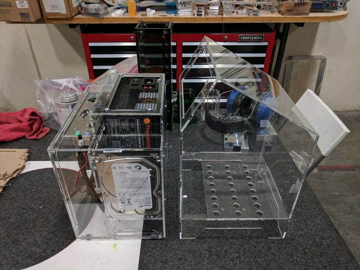
The blue LED decided to ignore my “nice soft glow” plan and put on an extravagant light show. It didn’t just light the top edge, it lit every edge of that acrylic sheet and had plenty of extra light energy to throw on the surrounding shelving.

FreeNASv2_LightsAbove

Here’s a close-up of the sideways illumination.

FreeNASv2_LightsSide

The many rays visible in the side illumination, as well as the lines making up the top illumination, indicate infinity mirror action going on inside that sheet. It wasn’t directly visible, and probably very difficult to photograph even if so. Without internal reflections, the blue light would have just gone straight up. But with the smooth surfaces and edges of the acrylic reflecting inside the sheet, the light of a single LED bounced around, found different angles, and was emitted in many more directions.

This LED illumination effect warrants further investigation. It is a happy accident that I fully intend to learn from, and put into future acrylic projects.

I want every acrylic project to look this awesome!


Luggable PC Wireless Module Installation

The point of the Luggable PC project is to build a mobile computer out of commodity desktop parts instead of more expensive specialized laptop parts. The upsides come from component choice, ability to upgrade piecemeal, and customization. One downside is that desktop components won’t have some of the parts taken for granted on modern laptops. Like today’s topic: wireless Ethernet.

The motherboard I currently have in the Luggable PC chassis (Intel DH87MC) does not have wireless Ethernet out of the box. I had been using a small USB wireless network dongle to provide wireless connectivity. The compact size is handy, but the compact size also restricts the antenna size, which in turn restricts performance.

The driver for the Realtek device isn’t anything to cheer about, either. It works OK in Windows, but it frequently fails in Ubuntu. I would frequently find myself without network access in Ubuntu and have to reset the USB adapter by unplugging it and plugging it back in.

I knew that my motherboard had a mini card slot for a wireless card. I also knew I had salvaged wireless cards from laptops I had disassembled for parts. But it wasn’t until today that I finally got around to plugging a wireless module into the Luggable PC.

I had also salvaged the matching antenna modules from the laptop. They formerly resided in the laptop lid, and now they are taped to the inside of the 3D printed enclosure.

Intel Wireless Card

Thanks to these two large(r) antennae, I now have stronger wireless signal and better data throughput. And the driver for this Intel-made wireless module has been far more reliable. And on top of all that, I’ve freed up a USB port.

One win for salvaged parts!

A Survey of Hosting Mechanisms in FreeNAS

After getting Plex plug-in up and running, I started researching the FreeNAS features for hosting other code. I plan to keep my FreeNAS box up and running at all times, as is typical NAS usage, to ensure files are available whenever I want them.  I wanted to know what else I can run on the box at the same time since it is going to be on and consuming electricity anyway.

From highest and most user-friendly level to the lowest, they are:

1) FreeNAS Plug-in: This is how I got started with Plex media server, as it is one of the few plug-ins on the default list. Some flaws with this system were visible immediately. The version of Plex on the default plug-in library is several versions out of date, and there is no user-friendly update mechanism. The user has to go into the FreeBSD jail and update manually. Similarly, in order to access the media files hosted on the same FreeNAS box, the user has to know about manually mapping storage into FreeBSD jails.

It feels like the FreeNAS plug-in ecosystem never matured as much as the creators had hoped. A sentiment confirmed by this page. It explained the reasoning behind the push in FreeNAS 10 (Corral) to move to a system based on Docker containers. Unfortunately, when FreeNAS 10 was abandoned, that push was also put on hold.

Summary: It looks like FreeNAS plug-ins are a dead-end for a deprecated architecture.

2) FreeBSD Jail: Since a FreeNAS plug-in user basically had to know about running a FreeBSD Jail anyway, they might as well learn to work at this more hands-on level rather than depending on the FreeNAS plug-in architecture to sugar-coat it. There are a lot more steps involved, but for popular things, somebody would have posted the list of steps. For example, here’s how to install Plex in a jail. (UPDATE: I’ve learned Plex media server is part of the standard package system and therefore even easier to install: Create a jail, open shell to the jail, type ‘pkg install plexmediaserver‘, done.)

Upside: FreeBSD jails’ isolation protects FreeNAS from some security exploits. The resources consumed by a jail is managed by the same system that manages the rest of FreeNAS and automatically gains all the benefits thereof. Storage in a jail can be mapped to a FreeNAS storage volume to allow (optionally read-only) access.

Downside: FreeBSD jails offers no protection against the nastier kernel-level security exploits.

Summary: FreeBSD Jail makes sense for running relatively trustworthy code that integrates with the volumes on FreeNAS. Plex media server is a good example.

3) Virtual Machine: New in FreeNAS 11 is a feature to create and run virtual machines alongside FreeNAS using the FreeBSD bhyve hypervisor. As of FreeNAS-11-0-U1, this new feature is quite immature. For example, trying to stop a VM in the FreeNAS UI seems to have no effect. I have to go into the administrative shell and use the “bhyvectl‘ command-line utility to stop the VM. As another example, the virtual UEFI boot sequence doesn’t act as some operating systems expect, which can result in the user getting dumped into the UEFI shell. (Something normal users should never see!)

UEFI Shell

Google pointed me to this page which will help with most Linux distributions that encounter this problem. Thanks to this tip, I got my Ubuntu test server up and running on a FreeNAS VM.

Upside: Full virtual machine isolation will protect against most security exploits.

Downside: Full virtual machine isolation consumes more system resources. Most significantly, the storage is not shared: Space dedicated to a VM is not available to the rest of FreeNAS. And there is no storage mapping so a VM could only access FreeNAS shares over the network interface as if it is physically a different machine.

Summary: Virtual machines make sense for things that do not interact with the rest of FreeNAS, and a good alternative to setting up another physical machine.

FreeNAS Plugin: Plex Media Server

plex-logo-e1446990678679Once I had a few simple network file shares set up in FreeNAS, it was enough to do most of what I want in a home network storage device. For a fraction of the cost of a commercial solution like Drobo. Now we can start looking at the less critical fun stuff.

Part of my home media collection stored on my NAS includes various video files that I’ve been carrying around. Most of them were standard-definition video files I recorded off of broadcast television programs. This was done at a time when most people would record to VHS tape. Only the super nerdy types record to computer video.

So I had the files, but I didn’t have a good way to play them straight off a file share. This is where something like Plex comes in. There’s a server-side component that runs on my FreeNAS box, talking to client-side components for various devices. The web client could cast to a Google Chromecast, and the Amazon Fire TV stick has a Plex client app.

For security isolation, FreeNAS runs plugins inside a “jail”. This is a FreeBSD feature that sounds a lot like a Docker container but isn’t a Docker container. This isolation is good default security, but it does mean the Plex Media Server plugin could not see the rest of the FreeNAS box until the user specifies a way for the code inside the jail to see specifically allowed files outside of a jail. I could even specify the storage visibility to be read-only so there would be no accidental manipulation of my video files.

Once I got past the FreeBSD jail mechanics, it was mostly smooth sailing. The only problem came from the large fraction of my files encoded in Windows Media Video format, an old video format that Plex does not support. If I end up deciding I like the Plex experience, I will have to look into doing a bulk re-encode of these old video files.

FreeNAS File Sharing: Trust the Wizard

FreeNAS LogoThe authors of FreeNAS tries to make things easy for the user by providing automation tools (“Wizards”) that take care of the fine administrative details without requiring the user to learn all the underlying nuts and bolts of FreeNAS, or FreeBSD, or Linux kernel, etc.

This is especially true for creating network file shares in FreeNAS. It supports many network file sharing protocols. Including the Apple-specific AFP (Apple File Protocol), the Microsoft Windows-based SMB (Server Message Block), the Unix-based NFS (Network File System), plus three others I don’t even understand.

Each of these have their own setup requirements that a casual user like myself is unlikely to get right on our own. So the manual encourages the use of Wizards. (Bold emphasis mine, but I think it should be in the manual!)

FreeNAS® provides a Wizard for creating shares. The Wizard automatically creates the correct type of dataset and permissions for the type of share, sets the default permissions for the share type, and starts the service needed by the share. It is recommended to use the Wizard to create shares.

Windows has a file sharing wizard as well: In Windows file explorer, I would create the folder I want to share, then right-click on that folder to select “Sharing…” This launches the wizard who will then take care of everything else.

Since I was used to the above workflow, I did the same thing in FreeNAS. Create a directory, then run the wizard to share that directory. Unfortunately this results in network shares that were not accessible. (“Access Denied”)

I eventually debugged the problem to my “create a directory” step. Since I had created as an administrator, the permissions on that directory were not set for use by other users. And the FreeNAS wizard did not (or could not) update the permissions properly.

What I needed to do was to launch the FreeNAS network sharing wizard, and tell it to create the directory as part of the network share creation process. This way the directory would be created by the wizard who will properly set the permissions for file sharing.

I did too much and that became unhelpful.

Trust the Wizard.

FreeNAS USB Flash Boot Drives: Recovering Boot Drives That Don’t Boot.

FreeNAS LogoWe’ve established that FreeNAS can mirror the USB flash drive boot device for redundancy. If one of them should fail, the system can be recovered with the other. I hadn’t set out to verify the recovery procedure, but I stumbled into a practice run anyway. In hindsight it’s good to get a feel of my recovery options now when I’m still playing with the system, rather than later when I’m in a panic to recover my data.

Over the past few days I’ve experimented with the boot volume, setting up the mirroring and using the built-in replacement mechanism to retire my USB sticks with checksum errors. After this was done, I unplugged the checksum-error drives (including the one I originally installed FreeNAS on) and rebooted the system.

It failed to boot and ended up at the GRUB recovery menu. Hmm, that’s not good.

I plugged all the old drives back in… and that didn’t improve the situation. Apparently, in the midst of all the mirroring and replacing, I managed to damage GRUB configuration so FreeNAS no longer boots.

Since I expected all the actual operating system files to be OK, I searched for a way to rebuild just the boot loader portion of the USB sticks. There are many ways to do this. The easiest – looking route I took is to perform an in-place upgrade.

I booted up the FreeNAS installation media, and selected the “Install/Upgrade” option. I pointed it to a USB drive that was free of checksum errors but would not boot. The installer detected an existing installation and offered to generate a new boot environment for the existing FreeNAS installation. Sounds perfect! I hit <OK>

Ten minutes later, the upgrade failed due to an error writing boot configuration files the installer wants to add. A quick Google search found a few suggestions on how to fix it using command-line tools I wasn’t familiar with. I decided to try easier things first.

I restarted the installation process and chose the other upgrade option: An upgrade with a disk reformat rather than just generating a new boot environment. The installer will preserve a copy of the FreeNAS configuration but wipe everything else from scratch.

This approached was more destructive and took more time but it worked. My FreeNAS box booted back up as if nothing happened. Success!

FreeNAS USB Flash Boot Drives: Wide Variations in Performance

Since I went into this FreeNAS project with the expectation to experiment and learn, I followed the recommendation to use commodity USB flash drives as the operating system boot drive despite my skepticism. The previous blog post discussed checksum errors found on some of the USB flash drives I had on hand, and how FreeNAS is able to mitigate the errors by mirroring the operating system across multiple USB sticks. This greatly increased my confidence entrusting the FreeNAS operating system to these USB thumb drives.

Usually these devices are used for ferrying files from one computer to another. They expect to see some files copied onto the drive, then copied off the drive in order. (sequential read/write operations.) Putting them in service as the operating system drive is an entirely different work pattern, with small pieces of data written at unpredictable places and other data retrieved from equally unpredictable places. (random read/write operations.)

I was aware of this difference and it was part of my skepticism using USB sticks as operating system drive. Now that I’m using it, I can see how it works in reality. Thanks to FreeNAS boot device mirroring, I have the confidence to go into this experiment without risking my data.

Outside of errors or outright failures, the other thing I had expected was degraded performance. If the flash memory controller chip is optimized for sequential operations, it might be bad at random operations. Unfortunately there was no way to tell up front. The software running on the flash drive controller isn’t something manufacturers put on the packaging. And every company has their own algorithm.

Since they are so cheap, the easiest thing to do is to just go and try it. The result is clear: some USB flash memory drive controllers are far far better at this workload than others.

Some of this difference is felt immediately, in the time taken for the mirroring duplication process. During this “resilvering” process roughly 2GB of data is copied to the new flash drive. Out of the two drives that had no checksum errors, one of them was able to complete the process in a little over two hours. The other took 26 hours, more than ten times longer!

Their difference is also visible in the FreeNAS system performance reporting page. Since FreeNAS keeps the two drives in sync, it’s easy to see how they respond to identical workloads. The flash drive identified as (da1) breezes through work, never more than 50% busy. Its mirrored sibling (da2) struggles to complete the same work, frequently spiking up to 100% busy.

DiskBusy

One of these is much less happy at their new job than the other.

Between the checksum errors and the disk busy graph, I am now much better enlightened on the varying quality of USB flash drives. I had thought of them as all basically equivalent, so I just bought whichever is the cheapest. My attitude has now changed. From here on out, whenever I need to buy USB flash drives, I’ll look for those made by SanDisk.

FreeNAS USB Flash Boot Drives: Mirroring For Fault Tolerance.

FreeNAS LogoFreeNAS encourages the use of USB flash drives as the operating system boot drive. This allows FreeNAS to dedicate all of the motherboard SATA connectors for data storage drives. I didn’t think commodity USB flash drives are trustworthy enough to hold the operating system, but I was willing to experiment and be proven wrong.

The very first night, I got worrying news from the nightly system check:

  pool: freenas-boot
 state: ONLINE
status: One or more devices has experienced an unrecoverable error.  An
        attempt was made to correct the error.  Applications are unaffected.
action: Determine if the device needs to be replaced, and clear the errors
        using 'zpool clear' or replace the device with 'zpool replace'.
   see: http://illumos.org/msg/ZFS-8000-9P
  scan: scrub repaired 3K in 0h10m with 0 errors
config:

        NAME        STATE     READ WRITE CKSUM
        freenas-boot  ONLINE       0     0     0
          da0p2     ONLINE       0     0    11

errors: No known data errors

Looking on the bright side, “No known data errors” is comforting, as is the “repaired […] with 0 errors”. It’s nice FreeNAS was able to repair whatever was wrong with my USB stick. I suspect inexpensive commodity USB flash drives frequently encounter errors that are silently corrected by the operating system. Still, an error is an error and it’ll only be a matter of time before I run into a serious problem.

Fortunately, FreeNAS authors had the foresight to make sure a bad boot device does not become a single point of failure. A second one can be added to the system act as a mirror to the boot device. If either of them fails, the other can take over.

Much to my dismay, the second USB stick I tried also encountered a data checksum error. I didn’t have much luck figuring out how to interpret the checksum error code, but I did learn that it is supposed to be zero. The first stick returned 21, the second 26.

I tried a third USB stick and was relieved to finally see a zero checksum. The output below was generated when I ran ‘zpool status’ while the third stick is in the middle of replacing the second stick.

  pool: freenas-boot
 state: ONLINE
status: One or more devices is currently being resilvered.  The pool will
        continue to function, possibly in a degraded state.
action: Wait for the resilver to complete.
  scan: resilver in progress
config:

        NAME             STATE     READ WRITE CKSUM
        freenas-boot     ONLINE       0     0     0
          mirror-0       ONLINE       0     0    21
            da0p2        ONLINE       0     0    21
            replacing-1  ONLINE       0     0     0
              da1p2      ONLINE       0     0    26
              da2p2      ONLINE       0     0     0  (resilvering)

errors: No known data errors

I also found a fourth USB stick that was checksum error-free, so I had it take the place of the first one.

  pool: freenas-boot
 state: ONLINE
  scan: scrub repaired 0 in 0h29m with 0 errors
config:

        NAME        STATE     READ WRITE CKSUM
        freenas-boot  ONLINE       0     0     0
          mirror-0  ONLINE       0     0    21
            da1p2   ONLINE       0     0     0
            da2p2   ONLINE       0     0     0

errors: No known data errors        

Now both boot drives in the mirror set have zero checksum error, but the mirror volume overall still has checksum error 21 from the first USB stick. I’m still learning if that means anything (bad) and what it would take to reset that to zero.

FreeNAS Box v2: Component Access

One aspect that was completely neglected in v1 was any kind of an access door. The panels were designed only enough for them to mesh, so the only way to hold things together is to glue everything shut. Completely impractical! The only way to perform any maintenance would be to shatter some acrylic to break the case open.

Now we have two access panels, one in the front and one on the bottom. I tried to see if I could somehow integrate things so there would only need to be one access panel, but never came up with a design that would work well while simultaneously satisfying all the other design goals I’m trying to accomplish.

Each access panel is held in by 4 x #6-32 screws, the standard desktop PC case screw. They fasten into threads I had tapped into the underlying layer of plastic. I should use heat-set inserts for better durability. Unfortunately I didn’t have #6-32 inserts on hand at the time and I thought I would probably build a V3 follow-up anyway.

FreeNAS v2 Front Panel Open

The front panel opens to allow access to the front chamber where the motherboard and CPU lives. If I wanted to upgrade the memory or switch out the SATA cables, I could do so through the front panel opening.

The bottom panel opens to allow access to the rear chamber. The two hard drives and the power supply are all installed through the bottom opening. The drives can be individually replaced without fighting through too many pieces of cable. The power supply can also be replaced through the opening exposed by the bottom panel.

FreeNASv2 Both Panel Open

FreeNAS Box v1 to v2 Size Comparison

Now that FreeNAS Box v2 is up and running, let’s do a size comparison to see how things have changed. The width dimension was a regression: v2 is wider by 3 centimeters. The real space requirement increased even more than that, because the v2 air intakes are on the sides.  So it needs additional room to the left and right of it in order to avoid blocking those intakes. In contrast, v1 with its bottom intake would be OK sitting flush against objects to its left and right.

Looking at the final results in reality, I think I can rearrange a few things to reduce the width by 1 cm. Something to consider for a potential FreeNAS Box v3.

FreeNAS v1v2 SideBySide

The greatest improvement is in the height which has been reduced by 7 cm thanks to the elimination of the lower air intake cavity. The advantage is somewhat reduced when in use, because the power cable now sticks straight up and adds a bit to the required height. If this becomes a serious problem, though, I could always switch to an power cable with a right-angle plug. This will allow the box to fit in a shelf only 28 cm high, leaving barely enough for proper heat exhaust. Looking over the results, I think I can safely reduce the bottom of the case by 1 cm and everything will still fit, another change for the potential v3.

FreeNAS v1v2 SideBySide

And finally, the depth is reduced by 3.5 cm. Real world improvement is even more, because now the back of the box can sit flush against the wall in a way that v1 could not.

The reduced height and depth has more than compensated for the increase in width, v2 is overall a more compact space-efficient package than the v1 design.

FreeNAS Box v2: Construction Complete

After spending an afternoon + evening at a Tux-Lab work session, I have my FreeNAS Box v2! It’s always fun to see my idea turned into reality.

FreeNASv2 Complete

The first thing I appreciated was the fact that the components are clearly visible through the acrylic panels. And even better, the messy tangle of wires are hidden behind them. This reversal from v1 is the best aesthetic change.

The other major design requirement – that both cooling fans be visibly spinning – is also present but it doesn’t have as much of an immediate aesthetic effect.

After I’ve kept it on and running overnight, I checked the temperature around the box the following morning. I think it would be neat to check thermal performance with a FLIR thermal imaging camera but lacking such toys I went with the low-tech way of putting my hands at various places around the box to feel the temperature.

The front chamber – where the CPU and motherboard reside – has a slight temperature gradient from top to bottom but overall it was relatively cool to the touch. This was expected as the CPU basically sat idle all night. It also means I won’t need to cut a hole in the front door for a direct air intake.

The rear chamber, with the power supply and both hard drives, is where most of the heat is generated. The two drives were warm to the touch signifying that they’ve been spinning all night and getting some amount of cooling to keep them from getting hot.

The power supply fan was running and the power supply case was cool to the touch. The power meter read 30W for the FreeNAS box in this steady-state idle state. This is a very light load for a 600W-rated power supply, reflected in its cool running temperature.

FreeNAS Box v2: Construction Fixture

One of the problems with FreeNAS Box v1 was that I designed it with tabs and slots to fit into each other. While it made the box easy to assemble, the slots severely weakened the structure of the box.

For FreeNAS Box v2 I avoid the tabs and slots. But I need something else in their absence to help me during construction. The answer is a fixture: Something I design along with the box that helps me build it, but not part of the end product.

Building the box will start with bonding all the major vertical pieces together. Once the cement has set hard enough for them to stand alone, the fixture pieces can be removed. The resulting assembly will then be self-supporting as the remaining pieces are attached.

The fixture pieces sit top and bottom. Pretty much where the largest horizontal pieces would eventually go, but are distinctly different from those pieces.

FreeNASv2 Fixtures.JPG
Initial assembly (gray) with assembly fixture (yellow)

The top fixture has two slots for holding two of the vertical sheets of acrylic. We’ve already established such slots are bad for the structural strength of the end product, but it’s perfectly OK (and quite useful) to have them in a fixture.

Both the top and bottom fixture have round cutouts in the corners and in the mid-span T-joint so that they stay clear of any extraneous acrylic cement that might leak out. This way we avoid accidentally cementing the fixture to the product.

Each of the fixture is made of two layers of acrylic, a main layer and a secondary layer whose shapes helps keep the box pieces in place. The small round circles visible in the picture is sized for M4 screws to fasten the fixture layers together. Using screws instead of acrylic cement allows us to later disassemble the fixture and recycle the pieces as scrap acrylic in future projects.

FreeNAS Box v2: Airflow Design

Designing the system airflow for thermal management is a huge consideration for the FreeNAS box design. The two fans in the system have been oriented for easy inspection first and then the airflow was designed second to work with natural convection flow. Lacking skills to use sophisticated thermal modeling and analysis tools, this design is mostly based on intuition.

Working as a network attached storage device is not a very computationally intensive task. Plus the CPU has its own fan, so thermal control of the processor is not a primary concern. The power supply also has its own fan, which I assume can take care of itself.

That leaves the hard drives as the primary thermal concern. Lacking their own cooling fans, the airflow design of the case will put them first in line to receive the coolest air. This meant placing them right at the intake. The v1 intake was on the bottom, so that’s where the drives were. The v2 intake air from the side, and again that’s where the drives were placed.

After the intake air has met the hard drive, the warmer bits should flow up and over the top of the hard drive, carried by convection towards exhaust. The cooler bits should head towards the rest of the case, helping to cool the motherboard and the CPU.

The motherboard and the CPU is in its own chamber. Cold air comes in the bottom and sides of this chamber and the top of this chamber has holes to send its warmest air into the power supply fan for exhaust.

If this proves to be inadequate cooling for the motherboard, we have the option of cutting an air intake hole directly in the front door panel of the case.  The CPU fan can then pull in cool air from the outside. This will reduce the amount of air drawn in past the hard drives, though, so I wanted to see how well it works before I start cutting holes.


FreeNASv2 Thermal Flow 2

FreeNAS Box v2: Additional Goals

We’ve just established all the problems exposed by the v1 prototype that we want to address for v2. In addition to those issues, we also want v2 to cover a few things that are no fault of the v1 prototype.

First one is relatively obvious: actually build a complete and usable case. I knew I was trying new ideas in v1 and that something will go wrong, so it wasn’t really complete. Even if everything went right (I knew it wouldn’t) I would have had to build a v2. For one example, I didn’t bother to design an access door.

We then have a few separate items that relate to improving space efficiency.

When I placed v1 on the shelf where I expected to keep my FreeNAS box, it wasted a few inches between the back and the wall due to the angle of the power cable. I want to rearrange things so that the back of the box can sit flat against the wall.

Cooling path in v1 started with air intakes on the bottom of the case. This was part of the tribute to the Apple PowerMac G4 cube, but functionally unnecessary while consuming vertical space.

Also contributing to the vertical space consumption was pointing all the ports downwards, like the PowerMac G4 cube. This made the ports difficult to access. It would be good to align the direction of all the plugs, so power and network cables can be in parallel.

Out of all the requirements listed here and in the previous post, the greatest impact was the “make sure all fans are visible for easy verification they are spinning” goal. It meant rearranging the components so both fans face forward. This made for an interesting design challenge as it is against common convention of computer case design. Once I got that set up, the configuration was then further refined in Fusion 360 to satisfy all the remaining requirements until we have this: my FreeNAS Box v2.

FreeNASv2

FreeNAS Box v1 Problems

FreeNAS Box v1 was a good learning project for acrylic construction. Here are the issues with v1 I want to address for the next version.

  1. Non-orthogonal joints: The laser cutter only cuts right angle edges. v1 had a few joints that were impossible to cement because the edges didn’t align at right angles.
  2. Tab and slot construction: To help align joints, I designed v1 with tabs to fit into slots I had also cut into their mating surfaces. While this made the box easy to build, it destroyed durability of the end product. The sharp corners of the slots are where acrylic starts cracking under stress. I had known about the dangers of sharp internal corners, but I thought acrylic cement would bond everything together eliminating the weak point. This idea has now been proven false.

    FreeNAS1_Cracks
    Stress cracks that started at corners of slots.
  3. Unappealing tangle of wires: The v1 box design placed all of the wires up front, which turned out to look pretty ugly, and all the components (hard drives and the motherboard) were hidden under the mess.

    FreeNASv1
    Yes, there’s a computer under the tangle of wires.
  4. Difficult access to components: Besides looking bad, the mess of wires up front also blocks access to everything else. It would be difficult to perform maintenance such as replacing drives if they fail.
  5. Cooling fans vulnerable to jamming: The wiring paths were such that, if some wires should misbehave and bend slightly out of position, they would impinge upon the blades of cooling fans stopping them from turning.

    FreeNASv1_Flaw
    Several wires in this bundle poked into the fan grill where it does not belong.
  6. Cooling fans are out of sight: Compounding the problem of blocked fans is the fact that despite the clear acrylic exterior, it was not easy to notice the fans were blocked.

I had to physically build FreeNAS Box v1 before I knew known any of the above are problems. Some I had thought about and didn’t think would be a problem, the others I just hadn’t thought about at all.

Gigabyte Z270N-WiFi and its F1 Firmware

When I embarked on the Luggable PC project, the primary goal was to build a computer using components I already had on hand. This translated into the requirement to accommodate full-sized desktop PC components. Now that I’ve used it for a while and started to like carrying my full-time computer around, I’m building up for an upgrade. This time, instead of building a chassis around components I already had, I will buy smaller components with the intent of assembling a new luggable chassis.

First up: The motherboard. Out of all the commodity form factors, the best balance of small size, computation power, and reasonable price is the Mini-ITX form factor. I’ve already worked with a few boards of that form factor, but none with leading edge components. This changes with the purchase of a Gigabyte Z270N-WiFi.

GigabyteZ270N-WiFi
Image by Gigabyte

The specifications of the motherboard looked great on paper. In additional to the small Mini-ITX form factor, the features important to my project are:

  • Support for Intel’s latest Kaby Lake generation of processors
  • M.2 slot for SSD
  • PCIe x16 slot for full-power GPU
  • Wireless networking

Factors that were not critical, but used as tie-breakers against its competition:

  • Dual-port Intel gigabit wired Ethernet
  • 6 SATA ports
  • USB-C port
  • Bluetooth

Looks great on paper! Sadly in reality the motherboard made a very poor first impression due to the onboard firmware. It was heavy on flashy looks and light on usefulness. I ran into many problems with basic functionality.

Example 1: The USB mouse support was useless: I could move the cursor around with the mouse, but clicking has no effect.

Example 2: Upon startup, it shows a full-screen Gigabyte logo (basically an advertisement) that I find annoying. If I select the firmware option to disable the logo, the motherboard no longer boots: I have to reset the firmware settings via jumper to get back to square 1. This was such an unexpected thing that it took three resets before I determined it was the logo setting that caused the problem.

So the “F1” version of the motherboard firmware was a disaster. Fortunately by the time I bought the board, Gigabyte has released updates and is currently on “F4”. Upgrading allowed me to disable the Gigabyte advertisement and still have a functional computer, in addition to addressing other functional annoyances.

This motherboard was clearly pushed out the door with incomplete firmware and the expectation on users to upgrade. I now have a good motherboard, but there’s a sour taste in my mouth from the bad out-of-box experience.

Water Damaged Nexus 5X Screen

The water-damaged Nexus 5X is somewhat functional again after cleaning off the swimming pool water chemicals, but suffers from a severe battery drain turning precious power into heat. This makes the phone unusable as a phone: it can only last an hour or two on battery, and being so hard on the battery raises worry of battery failure. Not “is the battery going to be flat?” kind, the really bad “is it going to burst into flames?” kind of worry. Before I put the phone aside (with battery disconnected) one final post about the screen assembly.

The screen is in bad shape even if the rest of the phone had fully recovered. The screen is legible and the touchscreen still works, but there are a lot of visually distracting marks left by liquid intrusion.

Liquid Screen.jpg

The big blotches in the center act like a bits of liquid still trapped in a gap. The size of the blotch changes depending on the pressure on the screen. I hope it evaporates in time, though I’m sure it’ll leave even more marks as it does. In contrast, the diagonal streaks do not respond to pressure and are likely residue left by drying liquid.

The obvious answer is to separate the touch digitizer layer from the display panel so I could clean the gap in between them. Unfortunately, even though the Nexus 5X is relatively easy to repair, this specific part is not repair-friendly. There are no more fasteners to access – the front of the phone, including the touch digitizer and the screen, appear to be a single bonded assembly.

Replacement assemblies are available online for $50-$60 dollars, which is a significant percentage of the $200-$250 asking price of a refurbished Nexus 5X. Even if the rest of the phone had recovered, I would have thought long and hard about spending that much money just for cosmetic concerns on a backup phone. And given the battery issue, the decision is clear to just leave it as is.

Nexus 5X, Hand Warmer

Power drain
Red rectangle marks the problematic hot area.

I’ve been pleasantly surprised at how far I was able to revive a Nexus 5X soaked in a public swimming pool for 30 minutes, but I think I’ve reached my limit.

All the phone functions I tested had worked, but using the phone for more than an hour uncovered a serious problem: something related to battery power management is very ill.

The first symptom was heat: the phone got far hotter than it used to, and trying to run the phone while plugged in to the charger resulted in a lot of heat and not a lot of increase in charge level.

I shut the phone down, unplugged it, and set it aside to wait for it to cool. It remained warm for many hours and never cooled. When I turned the phone back on briefly to check, I see the battery charge level has dropped dramatically. Something was draining battery power and turning it into heat even when the phone was turned off.

I knew most phones had two charging programs: One while the phone is on, running under the main operating system. And a second while the phone is off, run by a very minimal piece of code. I’ve already tried the first without success, so I turned off the phone and tried the second. Fortunately this was able to charge the battery though the phone still got pretty toasty.

After the battery was charged again, I disconnected the battery. Only then was the phone able to cool off. When I reconnected the battery, it was quickly obvious the heat source is under one of the pieces of metal shielding, marked in the picture by a red rectangle. I don’t know how to remove that metal shield without destroying the components underneath.

Two hypothesis are open: (1) this circuit was damaged earlier trying to run a ruined battery, or (2) the shield isn’t as watertight as it looks: there’s a lot of pool water chemicals in there corroding parts. Either way, it is beyond my current ability to address, so I have to stop here.

I can’t use this as a phone for more than an hour or two on battery. And I can’t store it with the battery connected because of the drain. So I’m going to disconnect the battery and put it aside in the hope I’ll have better ideas later.

Nexus 5X Reassembly after Cleaning

The Amazon Prime truck has delivered the aftermarket replacement battery and a syringe of thermal compound, so it’s time to put the phone back together.

The first order of business is applying a dollop of thermal compound on the frame where it accepts heat transferred from the CPU. Previously, there was a piece of pliable tape sitting in this square depression in the frame, but it was damaged by the alcohol and removed. The gray compound is intended for DIY PC builders to be applied between their computer CPU and its associated HSF (heat sink + fan) assembly. It is designed to bridge only a very small gap, since the CPU and the heat sink of a desktop PC are in physical contact and this compound only needed to fill the remaining tiny air gaps. Here it is asked to bridge a much large gap of almost 1 mm with no physical contact between parts.

Thermal compound

The reassembly went smoothly until I installed the aftermarket battery and found the connector cable is too long by a few millimeters. It is a large distance in the tight confines of a cell phone’s guts. Looking on the bright side, I guess it is better to have a connector cable that’s too long rather than too short.

Too long

With the connector plugged in to the appropriate location on the main circuit board, the cable is bent at an angle that won’t fit under the rest of the phone.

Bent

As much as I hated to do it, I pressed down the cable and made a sharp fold in it. This is a recipe for metal fatigue and the cable won’t last long if I keep doing this. Well, at least the battery is cheap.

Folded

Folding the battery cable allowed the rest of the pieces to be fully reassembled. The phone can power on and launch into Android, so the basics look OK and clear the way for more testing. Let’s see if the phone works well enough to justify replacing the screen assembly.

Powering Up the Waterlogged Nexus 5X

After waiting overnight for the re-cleaned parts to dry, I reassembled the phone and pressed power. The lack of response was no surprise. I then plugged the phone into the charger and was very encouraged to see the screen light up with the depleted battery icon. This tells me the some of the phone made it through the ordeal in at least partial working order.

But after a few hours, the situation did not improve. So I took the phone apart again to take a closer look at the battery. When I first took the phone apart to soak in distilled water, I measured the voltage across the connector terminals and got 3.0 volts. It was lower than healthy for a lithium battery but not necessarily fatal. I measured it now – after charging for several hours – and it read zero.

So, that’s not good.

I thought the battery cell might be dead, so I got another one to test my hypothesis. I wanted the connector from the existing battery so I cut apart the plastic wrap to extract it. I was surprised to find that there’s a tiny circuit board inside. I’m not sure what that circuit board does… but looking at its current condition, it’s not doing that job anymore. Since I didn’t know it was there, it didn’t receive the water + alcohol cleaning treatment received by the rest of the phone electronics. It has been under attack by swimming pool chemicals for the past few days.

Battery Board Toast

Well, I wanted the connector, and now I can access the connector. Let’s use it to wire up the lithium cell straight up. There were four soldering contacts on the connector, two with large conductors and two with small conductors. The two large ones were helpfully labeled “V+” and “V-” so that’s how I soldered the lithium cell.

Battery hackAnd it worked! This setup was sufficient to get into the Android OS. Now that the screen is showing more than the “depleted battery” icon, I could see that it was damaged in this adventure. Thankfully it was still legible, and the touchscreen still worked, so I could run the phone for about 40 minutes. Long enough to access the multi-factor authentication app so I could transfer my MFA security to another phone.

Since the phone appears to be running, I ordered a proper replacement battery. I don’t know if the corroded battery circuit board did anything bad to the rest of the phone. The charging circuit may have been damaged trying to charge a zero volt battery for hours. I’m going to see how the phone works with the replacement battery before spending money to address the damaged screen.