 The dimensions for my Luggable PC project were determined by the components within. The width and height, specifically, were dictated by the LCD screen module. Even though I made the CAD files public for anybody to build their own Luggable PC, in practical terms only people with the exact same LCD module would be able to use the files without modification.
A friend who saw the Luggable PC was interested in generalizing the concept and create a frame for lugging a (not disassembled) screen alongside its (also not disassembled) PC. Relative to my project, it would be easier to build and less specialized to the components within, with a trade-off in larger size and heavier weight.
I thought it was a great idea to explore and joined in the experiment. We each came up with a design, and we built both of them at Tux-Lab to see how the ideas translated into reality.
This blog post is a brief summary of my first experiment.
The Components
The monitor is an Yamakasi Catleap monitor, built around a 27″ IPS panel with 2560×1440 resolution. The specific dimensions don’t really matter, as it will be mounted via the standard 75mm VESA pattern on the back. Any large monitor with 75mm VESA pattern would fit as-is, and only minor modifications would be necessary to accommodate monitors with a different mounting pattern.
The PC is a HP Z220, small form factor PC from the HP business line available with a range of components to trade off processing power against price. For the purposes of this experiment, the important details are its height of 331mm and depth of 100mm. Thought not a standardized dimension, many small form factor PCs are roughly the same size.
The Construction
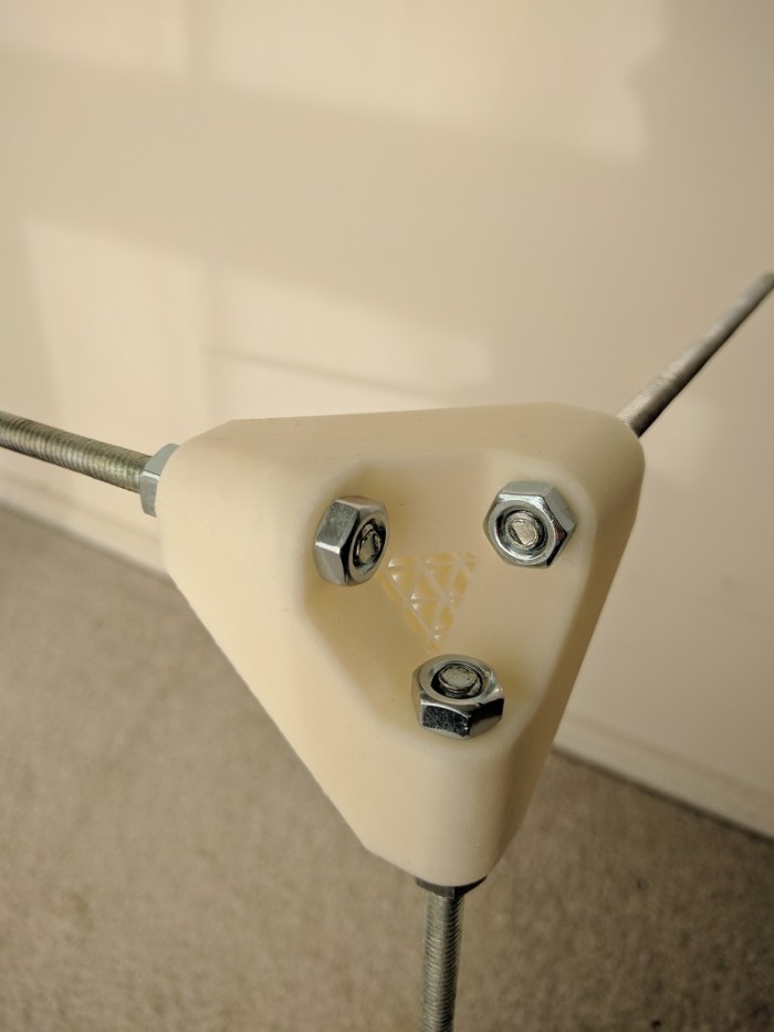
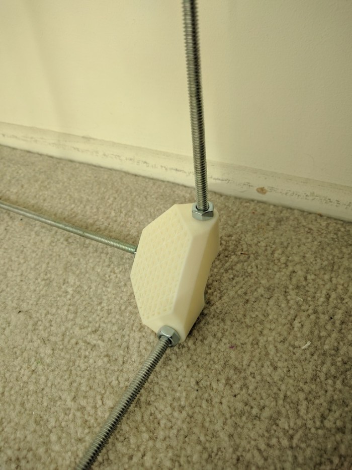
The core of the frame are built from 15mm aluminum extrusions (Misumi HFS3) for strength and the remainder of the frame are made from 6mm laser-cut acrylic fastened to the extrusions via M3 nuts and bolts.
Making the panels from laser-cut acrylic has the advantage of simpler modifications. Many of the critical dimensions in my Luggable PC 3D CAD file has the problem that, when changed, they trigger cascading changes that need to be reconciled. When designing for the 2D tool path of laser laser cutting, it is easier to keep modifications in mind so that a change in one sheet does not cascade to other sheets.
Example #1: The frame has a 331mm x 100mm hole to fit the Z200 case. This can be adjusted to fit any other SFF frame without cascading changes to other components.
Example #2: The monitor mount pattern can be changed, and the mount position can be moved up or down to adjust elevation of the monitor.
The Result
 I had never designed for laser cutting before and was happy for the chance to do something on the Tux-Lab laser cutter. I knew that, having little experience with the material, my first few designs will have some amateurish flaws. So this frame #1 was fairly minimalist just to see what happens.
I didn’t have a good grasp how many fasteners I would need to hold everything together. I laser-cut roughly double the number of fastener positions than what I think I would need, as it is easier to have more options rather than less. For the assembly I only installed fasteners in every other hole.
The screen mount was surprisingly successful. We questioned whether 6mm acrylic would be suitable for holding up the Catleap monitor by its 75mm VESA mounts. When we found some worrisome flex, the suspicion went immediately to the 6mm acrylic but it turned out the Catleap monitor enclosure was the source of the flex.
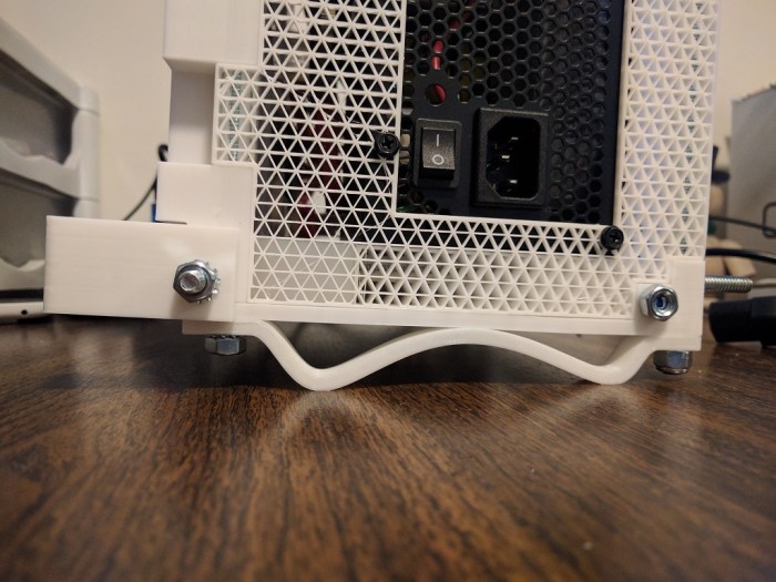
When attempting to install the PC, we found that the case itself would fit just fine but the rubber feet attached to the side of the case did not. I added cutouts in the CAD file but it seemed wasteful to cut entirely new pieces of acrylic just for the little feet cutouts. For purposes of experimentation, a Dremel tool was used to cut gaps to clear the rubber feet.
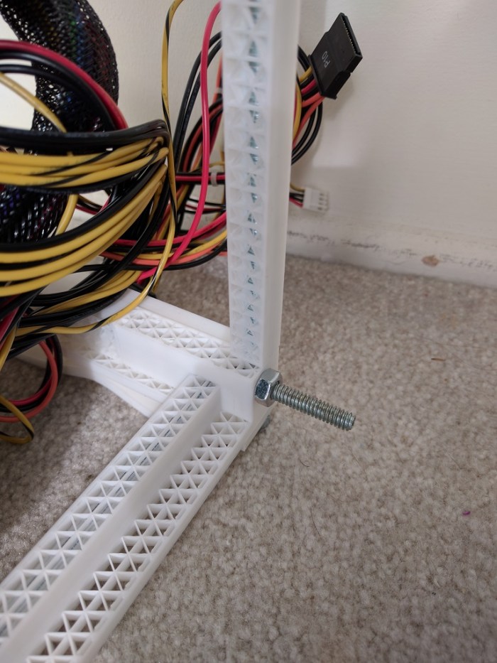
After the frame was assembled with the screen and the PC, we started plugging in all the cables and wires and I realized I had forgotten to account for the cables. There’s no good place to coil up the excess so they kind of dangle and stand ready to catch on something inconvenient.
The entire assembly was built in a tiny fraction of the time of my Luggable PC and included a much larger monitor with a much higher resolution. The trade off was almost doubling of the weight. The handle, part of the acrylic assembly, appeared to be sufficient to manage the weight.
I carried it across Tux-Lab and quickly encountered the first failure.
The Failure
Lesson of the Day: Sharp internal corners are bad.
My amateur mistake was cutting a sharply cornered rectangle to hold the PC. The sharp corners concentrated the physical load of the PC into a small point in the 6mm acrylic, which protested the poor design by breaking apart.
The next experiment will incorporate this lesson.
Build, fail, learn, iterate, repeat.


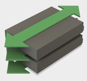
 Portable External Monitor version 2.0 (PEM2) explored a different construction technique from PEM1. Instead of building a box by assembling its six side pieces (top, bottom, left, right, front back) the box is built up by stacking sheets of acrylic.
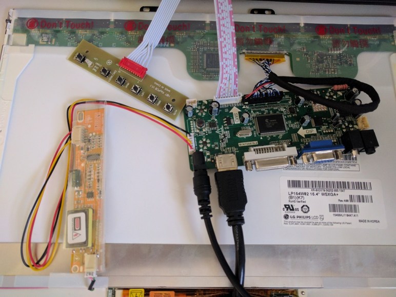
 Once the LCD panel and matching frame had been salvaged from the laptop, it’s time to build an enclosure to hold it and the associated driver board together. Since this was only the first draft, I was not very aggressive about packing the components tightly. It’s merely a simple big box to hold all the bits checking to see if I have all the mounting dimensions for all the circuit boards correct.
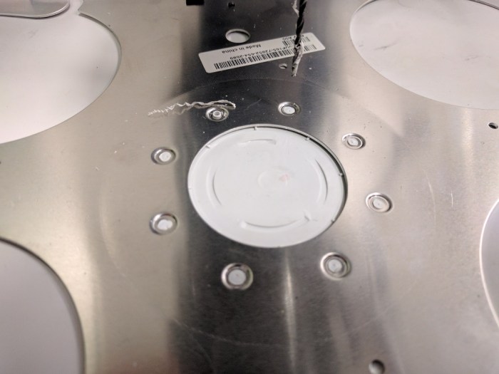 My Luggable PC display was a LCD panel I had salvaged from an old laptop, which I’m doing again for this external monitor project. When I pulled the Luggable PC panel out of the old laptop, I left most of the associated mounting hardware behind. During the Luggable PC project I wished I had also preserved the old mounting hardware.
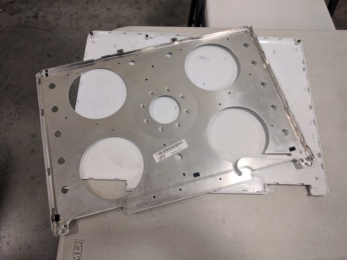
 Before diving into building FreeNAS box #2, I thought I’d take a pause and take a closer look at the acrylic construction results of experiment #1. This is purely about learning to build structures from acrylic – independent from the positive or negative aspects of the project as a computer enclosure.
 With the concept designed, it’s time to head over to Tux-Lab to build it!
 On the back side of the tilted-PSU, we see that the tilt has pressed the bottom of the PSU up against the wire bundle at the top of the motherboard. The tight quarters mean individual wires of the bundle tried to relieve the crowding by moving into the space for the PSU fan preventing it from turning. Since the PSU fan is the primary air-mover for this enclosure, a stopped fan is obviously not acceptable.
 Once the components are gathered, we start thinking about designing an enclosure for them. The tool of choice is the
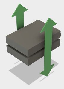

 Following the lead of the G4 Cube, air intake will be on the bottom and the power supply (with its fan) will sit at the top to work alongside natural convection and exhaust hot air.
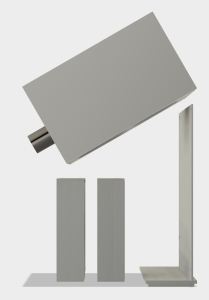
 The brains of the system will be a Mini-ITX board, the MSI
  The second iteration of the luggable frame experiment addressed the failings of the first version by relying less on acrylic and more on aluminum. The first iteration was a good experiment to see if acrylic was strong enough for the work. Once V1 conclusively proved the weaknesses, it’s time to fall back to the known quantity.
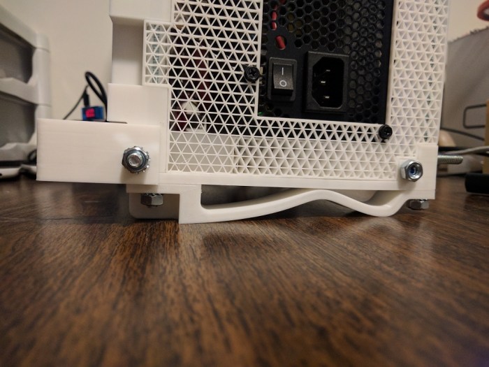
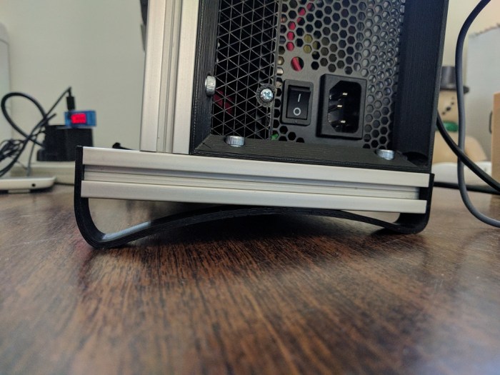
 PC tray upgrade: This was the first acrylic thing that failed in V1. The PC is now held in place by aluminum structure instead of an acrylic cutout which makes it quite secure. Three of the extrusion right-angle connectors were re-purposed as “claws” to keep the PC case in place.
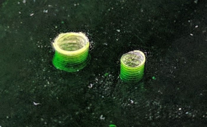
 VESA mount upgrade: The worrisome flex in the Catleap monitor enclosure was traced down to the metal threads inside the Catleap enclosure that were longer than the thickness of the enclosure plastic. This meant when the mounting screws fully engaged, there was still a bit of space between the VESA mount plate and the monitor’s rear surface, allowing movement. A spacer plate was added to fill that gap. Now the VESA mounting plate on the frame is fully pressed against the monitor’s rear surface, greatly reducing the flex.


 The easiest solution to that problem is to rotate the whole works 90 degrees. I tried it for a while and the upright screen sitting at table height level was ergonomically poor.
 The wasted volume between the screen and the motherboard was another problem exposed by this prototype. The space looked small in CAD because the CAD model blocked out all the volume allocated by ATX spec. Since the actual motherboard consumed only a fraction of the allocated volume, the real world example had far more wasted space.
 I had the idea to solve both issues by raising the screen high to eye level, oriented horizontally, and tilt it into the empty volume. I never got as far as building it. Looking at the CAD layout, it is quite clear that the horizontally-oriented screen sticks out on either side of the case. This makes for a shape awkward to transport and also leaves the screen extremely vulnerable to damage. The screen height was good, but everything else was bad.