First Impressions of CarPlay and Android Auto Receiver (TTXSCAM T86)

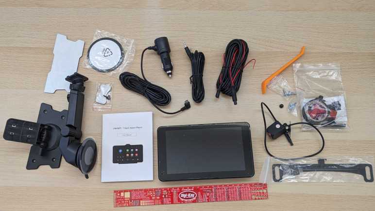
After I quickly reviewed everything that came in the box of this TTXSCAM T86 CarPlay/Android Auto receiver I bought via Amazon (*) it was time to power it up to see it in action. There were two test configurations. The first was powered by a solar charged battery and desktop speakers, the second round were powered by my car’s battery and output to my car’s speakers via an aftermarket audio input port. (Sylfex AuxMod Basic, now discontinued.) My observations are as follows:

The first thing I measured was the visible display area, and it was good news: it almost matched the size of stock navigation screen bezel. 4mm narrower in width and 3mm shorter in height, this is as close of a match as I could hope for. Mounting this inside the existing navigation hood would leave only a negligible black border.

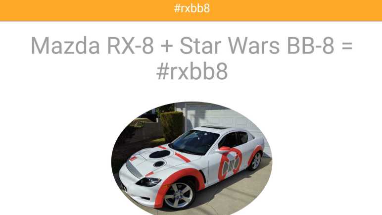
When booting up, the screen displays this image which I think depicts a McLaren 720S. I want to change this image to maybe the Mazda logo or a picture of my own car, but I couldn’t figure out how. The device also emits a little musical chime on startup on both its internal speaker and the audio line-out port. I didn’t find a way to change or silence that, either. Neither of these boot-up behavior is a deal breaker but customization would be nice.

The device home screen has a few functions, the only one I cared about was “Android Auto”. Pairing it with my phone as a Bluetooth peripheral enabled Android Auto. Scrolling around Google Maps on this device, I found the system responsiveness to be merely acceptable. There’s a noticeable delay between input and response, and scrolling animations are chunky. It feels roughly on par with <$100 USD Android phones commonly sold with prepaid cellular services. I am optimistic the device’s sluggish response won’t matter, because if I want to do something like putting in a new address for navigation, I can use my (much more responsive) phone’s screen.

Once connected to my phone, this receiver will try to reconnect to my phone every time it powers up. I counted ~30 seconds between turning on power and projecting information from my phone. It’d be nice if this was faster, but ~30s should be fast enough for everything to be up and running by the time I’ve backed out of the driveway.

Speaking of which, I also did a quick test of the bundled backup camera. I just connected the wires, no mechanical mounting. The camera is just sitting on the floor looking at my feet. With the camera connected and the signal wire tied to input voltage (emulating the power line of an illuminated reverse gear light bulb) it only takes ~10 seconds between screen power-on and showing backup camera view. This is roughly on par with the amount of time I allow the engine to settle down to idle before shifting into reverse, so I’m also filing it under “would be nice to be faster, but probably fast enough” as well.

When using audio line out, to my car’s audio input port, I could control sound volume with the existing sound volume control knob or steering wheel controls. This worked as expected with no surprises.

Screen brightness is another story. The factory navigation system automatically adjusts screen brightness based on an ambient light sensor and a signal wire indicating if headlights are on. I can’t tell if there’s a brightness sensor built into this device, but it definitely doesn’t have the headlight state. I have to manually adjust brightness to fit ambient light. I neglected to look for this aspect when listing my shopping criteria, oops. I’ll have to see if this bothers me enough to make me pay for an upgrade.

I’m encouraged by the almost-perfect screen size fit, fast-enough startup time, and integration into existing volume control. I can probably learn to ignore the startup image and chime. I’m not so sure about screen brightness behavior, but that’s not an immediate deal breaker. This cheap thing is not excellent, but it seems good enough to meet my needs. Before I take my car interior apart, though, I should do my homework and study information available online.


(*) Disclosure: As an Amazon Associate I earn from qualifying purchases.

Unboxing Wireless CarPlay and Android Auto Receiver (TTXSCAM T86)

I wanted to add CarPlay/Android Auto capability to my 2004 Mazda RX-8 by replacing the screen of the ancient Mazda factory navigation system. I picked out a standalone wireless receiver with features I liked and a physical size that I hoped would fit. When my TTXSCAM T86 (*) showed up, there was a satisfying quantity of stuff in the box.

I immediately went to the manual (which called the device a T86MP5) and found it to be nearly useless. A thin booklet of 22 meager pages that didn’t cover basic information like installation or anything about the backup camera. I think I’m on my own to figure out most of this device.

It came with two sets of mounting hardware. One for the top of the dashboard, either by the included double-sided adhesive or four fastener holes. And the other is a suction cup mount either to the windshield or to the included a smooth plastic disc, also with double-sided adhesive. I will mount this device inside a piece of existing interior trim, so I won’t be using either of these mounting arms.

It also came with a 3.5mm stereo audio cable, and a power cable that plugs into the de facto in-car power source form factor that traces its origin to a cigarette lighter. The device end of this power adapter is a USB type C plug, but this adapter is not a full USB PD (Power Delivery) source. It only claims to deliver 5 Volts at up to 3 Amps.

Majority of the parts count are associated with the backup camera. Electrically, there’s a wiring harness long enough to run the length of the car, various zip ties and other cable management tools, even a roll of electrical tape. I didn’t recognize the red plastic pieces and had to search online to learn they are T-tap connectors. Further reading taught me I am supposed to use them to tap into the reverse light power wire, so the system knows to turn on the backup camera.

Mechanically, this package included a license plate bracket and associated hardware to mount the camera top and center above the license plate. I can’t use this directly as-is because the RX-8 has its license plate illumination light centered above the plate, and this mount would block that light with the camera. I will have to modify the bracket, or existing light, or get creative with something else.

I was charmed by the inclusion of a few tools. A tiny screwdriver to work with the small camera-mounting screws, and a large piece of orange pry bar for removing interior trim. Something I’ll be doing a lot to run the camera wiring harness through the car. Looks like a proper backup camera installation will be a lot of work. Fortunately, I can put that off until later. The next order of business is to explore how this receiver works with a benchtop test.


(*) Disclosure: As an Amazon Associate I earn from qualifying purchases.

CarPlay and Android Auto Receiver for 2004 Mazda RX-8

I wanted to add CarPlay/Android Auto capability to my nearly twenty-year old car and as soon as I learned standalone receivers existed, I knew that was the direction I wanted to go. I started looking for a good candidate for installation inside existing navigation hood. It’s a little motorized retractable pod where Mazda housed the screen for the factory navigation system, and fitting into that pod will be the primary physical constraint. In addition to physical size, there are several other evaluation criteria:

Screen

Annoyingly, screen size is the next most important constraint, yet it isn’t something I can confidently determine. I want to buy a unit with visible screen area matching the factory navigation screen, so it fits perfectly in the original bezel, but the exact height and width are never specified. The best I can do is look for a “7-inch class” diagonal screen, excluding significantly larger and smaller screen sizes. I also excluded wide aspect ratio screens like this example. (*) A wide screen is a great idea for sitting on top of the dashboard, the intended use these standalone receivers. Showing more data without being too tall and blocking the driver’s view. But I want to fit into an existing 16×9 aspect ratio bezel, so those novel designs are out.

For the display panel, I personally prefer IPS panels for their color and viewing angles. Some units use a TN panel which will probably suffice. (The original navigation screen was likely a TN panel.) I don’t think they make VA panels at these small sizes, but they would also suffice. And finally, I’m not willing to pay the premium for an OLED panel here. Their stunning contrast ratio would be lost in the interior of a car, and there’ll be a lot of infrequently changing pixels risking OLED burn-in. Making OLED a poor choice for this application.

Most of these 7-in screens list their resolution as 1024×600. This is pretty low by modern screen standards, but it’s going to be mounted in a car further away than my usual computer and phone screen distance, so it might be fine. I’m confident it’ll be an upgrade from the factory navigation screen resolution! If resolution proves to be a limitation, I’ll come back and pay extra for a unit with a 1920×1080 screen.

[UPDATE: It would be nice if the device automatically dimmed the screen when dark. I forgot to look for that in my first device, it’ll be added to the criteria list if I shop for another.]

Touch Input

Capacitive touch technology has taken over everything, I didn’t see any of these receivers listed with a resistive touchscreen. My concern with capacitive touch is their sensitivity to environmental interference. A resistive touchscreen will only react to physical forces. A capacitive touchscreen might be affected by the plastic bezel, mounting hardware, or other electronics in close proximity. But given the lack of non-capacitive options I just have to give it a try.

Camera

Since these things are designed to sit on top of our dashboard, some (like the wide aspect ratio item linked above) integrated a front-facing dashboard camera. Since I want to bury mine inside the factory navigation hood, that feature would be useless for me. On a related note, several included either provision for a backup camera or comes packaged with one. This caught my interest. RX-8 rearward visibility is not great, and I’ve occasionally wished for a backup camera.

Audio

For audio output, these devices all have a little built-in speaker for when they’re sitting on the dash. Since I want to integrate it into my car, I want units with a line-level audio output jack. Some of these units can also act as a FM transmitter so we can tune in with the radio, which might sound better than the tiny built-in speaker but not as good as line-level audio signal.

They all have a built-in microphone for audio input, for use with Apple’s Siri or Google’s Assistant. Some of them have an audio input jack for an external microphone, and some have provision for an external button to activate voice commands. I never use voice input, so this was irrelevant to me.

Wired or Wireless?

I’m torn on whether to go for wired CarPlay/Android Auto or wireless. A wired interface will be immune to RF interference and will charge up my phone while in use. Wireless will be more convenient, and one less cable I have to route under trim panels in the car. I can go either way and if it proves to be a problem, I could buy a unit with the other connection method.

Winner

Criteria above culled Amazon listings down to about two dozen very similar products from brands I’ve never heard of. Not knowing how to evaluate differences, I do what most Amazon shoppers do: sort by price. I then clicked “Add to Cart” for a TTXSCAM T86 (*) which had the following features:

  • 7″ IPS capacitive touchscreen with 1024×600 resolution.
  • Bundled backup camera, no front facing dashcam.
  • Audio-out jack in addition to built-in speaker and FM transmitter.
  • Built-in microphone only. No audio-in jack or voice activation button.
  • Wireless CarPlay and Android Auto

This is a very affordable unit. I thought I would start here and, if I find anything annoying, that would teach me reasons to justify going upscale. Keeping things cheap also means it’ll be less intimidating to modify as needed to fit my car. Once it arrived, I looked over everything that came in the box.


(*) Disclosure: As an Amazon Associate I earn from qualifying purchases.

Standalone CarPlay/Android Auto Receivers Exist

I wanted to put CarPlay/Android Auto capability in my car, which is approaching twenty years old. The known solution displaces factory audio with a double-DIN bay for an aftermarket head unit. I decided against that path, because I wanted to keep the factory audio head unit (and all its electronic and stylistic integrations) intact. Instead, I want to put that capability where the factory navigation system screen sat.

Mazda’s factory navigation screen sits in a little motorized hood that retracts when not in use and keeps a screen close to a driver’s field of view while in use. I liked that position and thought perhaps I could fit an aftermarket unit within that volume. It has enough width and height to match a double-DIN bay, but only a fraction of the depth. This is not a problem because we’re not dealing with CDs or cassette tape mechanisms so modern head units can be very shallow. For example, this unit (*) claims to be a mere 1.77 inches (probably designed for 40mm) deep. Possibly small enough to fit in the stock navigation hood. Another potential candidate is to buy a unit like this one (*) that fits in a single-DIN bay and connects to an external screen. I could mount that screen in place of factory navigation screen and find some space nearby to mount the main body.

I knew these solutions are overkill, because they are full audio head units. Meaning they have their own speaker amplifiers, AM/FM tuners, and many other components that I don’t really need because I’m keeping Mazda’s stock audio head unit. I had searched for head units because I didn’t know any better, but Amazon search algorithm helped me out: it started suggesting sale listings for standalone CarPlay/Android Auto receivers. I didn’t know these things existed! But as soon as I understood they were available, I ignored the full audio head units. Standalone receivers are even shallower and, I hoped, more amenable to creative mounting schemes. Which of many offerings listed on Amazon would be a good replacement for a 2008 Mazda RX-8 navigation screen?


(*) Disclosure: As an Amazon Associate I earn from qualifying purchases.

Going Off the Beaten Metra Path

My 2004 Mazda RX-8 was factory equipped with an optional in-car navigation system, but the map data and the electronics behind it are now twenty years out of date. Potential upgrade ideas evolved over my two decades of ownership, but I never got around to any of them. Now I’ve decided to give my car a modern (for now) capability: connect to a phone via Apple CarPlay or Google’s Android Auto.

A typical upgrade solution is to replace the factory stock audio head unit with an aftermarket unit. There’s a large selection of CarPlay/Android Auto capable products, like this randomly chosen example Pioneer DMH-W2700NEX. (*) Such replacement is relatively easy for dashboards that conform to the dual-DIN standard for audio head units. Unfortunately, interior design has been moving away from that standardized format, a trend that included my car. Stylistically integrating audio with the rest of interior now hinders my attempted upgrade.

Fortunately, the aftermarket has an answer for that as well, in the form of Metra 95-7510HG. (*) This kit replaces the entire center console panel with a new facade that accommodates a dual-DIN head end. The “HG” suffix has a glossy finish that matches the stock panel, the version without “HG” prefix may blend in better with the rest of the interior which did not have a glossy finish. There’s also a single-DIN variation with a little storage cubby, but that would be too small to accommodate a CarPlay/Android Auto touchscreen. In all cases, we lose the circle themed Mazda styling on the original panel.

The price tag on these kits is far more expensive than a plastic panel and a few brackets, because there’s a fair bit of electronics that have to be installed as well. Remember that interior integration trend? This panel, formerly hosting the audio controls, also hosts the HVAC controls. Plus, sitting above this panel is a single glowing red screen displaying both HVAC and audio status. The Metra kit includes electronics to interface with the HVAC and status display. It also interfaces with the steering wheel audio controls. And finally, a critical safety item: the emergency flasher button is also part of this assembly.

Searching on the RX-8 owner forum, I found many reports that the Metra kit is not a seamless experience. There are complaints about mechanical fit, cosmetic finish, and electrical gremlins in the electronic interface translators. They’re all solvable problems except for the last one: I don’t usually look down that far when driving. My car already has a screen up high in my normal field of view. I want to use that location. Based on the above criteria, I decided against the Metra kit and will try a different route.


(*) Disclosure: As an Amazon Associate I earn from qualifying purchases.

Replacing Factory Navigation for 2004 Mazda RX-8

I am slowly grinding away at learning FreeCAD, hoping to get good enough so I can use it for future projects. There’s not much to write about learning the ropes, so I’ll write about a different project currently underway in parallel. I had recently concluded a cosmetic art car project, removing Plast-Dip I applied to make it resemble Star Wars’ BB-8. Now my car is back to its factory blue color, and I want to tackle an item that’s been on my to-do list for a long time: upgrade the in-car navigation system.

Mazda offered the 2004 RX-8 with an optional in-car navigation system. It was an expensive add-on, but I was young and flush with a tech salary, so I got mine so equipped. This luxury far predated the age of everyone having maps on their cell phones. (Reminder: the first iPhone launched in 2007.) Add-on units from Garmin and TomTom existed at the time, but the factory options were superior for several reasons:

  1. Spoken directions are piped through the audio system instead of a tiny speaker on the dash.
  2. A dedicated GPS antenna with a better view of the sky than a box in the cabin.
  3. It has access to vehicle speed and direction to estimate position if GPS signal is lost.
  4. Does not occupy a power socket and does not require a tangle of wires.
  5. Screen is elegantly integrated with the interior, not a suction cup on top.

I knew map obsolescence will become a problem at some point, but I wasn’t too worried. At the time I had expected to trade the car in for another one in a few years, I didn’t expect to love the car enough to still have it today. A 2004 model year car that I bought in 2003 means the map data was probably compiled in 2002 if not earlier. This is now quite old, and I don’t recall ever hearing anything from Mazda about map updates, for free or for fee.

One advantage of having the optional factory navigation system is that, if I wanted to tackle an upgrade project, a lot of wiring is already in place as well as the factory interior trim pieces to accommodate a navigation screen. But what would this upgrade project entail? The project ideas evolved as the years went on. Early in my car ownership, I contemplated converting the in-car navigation system to an in-car Windows PC running Microsoft Streets & Trips and patched to the in-car GPS antenna. That would have been a hugely complex project, so I never got started. For a simpler alternative, I considered shucking a Garmin free of its factory enclosure and integrate it into the car, but that never happened either. Then online maps like Google Maps got good enough I thought about replacing the factory navigation screen with an Android tablet with Google Maps running offline maps downloaded at home via WiFi. While I procrastinated, data plans got cheap enough for our phones to use live data online. So, I thought about putting a phone mount inside the factory navigation hood.

None of those happened, but I’m finally tackling the project now. The current state of the art for in-car integration takes the form of Apple CarPlay and Android Auto. That’ll be my target but I’m taking an unconventional route.

Code for Load Cell Experiment (ESPHome YAML Lambda)

I’ve got a set of inexpensive load cells hooked up to log signs whether I’m getting a good night’s sleep. It was an experiment that was both interesting to me and fits within the quite-significant limitations of these cheap little things. I’m going to leave that setup collecting data for a while, in the meantime I want to write down details on the software side before I forget.

I did not try to compensate for temperature or for system warmup, those two together could affect final weight output by as much as half a kilogram. But in the specific purpose of tracking changes on a minute-by-minute basis, those factors could be ignored.

This sensor and HX711 amplifier combination has a recurring issue sending occasional readings that do not reflect what’s actually happening. To minimize effect of these spurious data points, I have taken the following measures:

  • The reported weight value is the median weight out of the past minute and a half. Median value filter is more tolerant of spurious data of drastically different values.
  • Once I had everything set up, I noted the minimum measured value (empty bed) and the maximum expected value (bed with me in it) and discarded all values outside of that range as “Off Scale Low” and “Off Scale High”. That will throw out some spurious data but still leaves those within the expected range.
  • The reported delta value is not the difference between the maximum and minimum values seen within a time window. I track the second-largest and second-smallest values and report that delta instead. This way I can ignore spurious outliers, though it only works as long as spurious data doesn’t happen multiple times within a minute. Fortunately that’s been the case so far. If the problem gets worse I’ll have to devise something else.

And here’s the ESPHome YAML. If you want to copy/paste this code, feel free to do so. But make sure the values of hx711 “dout_pin” and “clk_pin” matches your hardware. The constants used to filter off-scale high/low will also need to be adjusted to fit your setup:

sensor:
  - platform: template
    name: "Delta"
    id: load_cell_delta
    accuracy_decimals: 0
    update_interval: never # updates only from code, no auto-updates
  - platform: template
    name: "Off Scale Low"
    id: load_cell_toolow
    accuracy_decimals: 0
    update_interval: never # updates only from code, no auto-updates
  - platform: template
    name: "Off Scale High"
    id: load_cell_toohigh
    accuracy_decimals: 0
    update_interval: never # updates only from code, no auto-updates
  - platform: hx711
    name: "Filtered"
    dout_pin: D2
    clk_pin: D1
    gain: 128
    update_interval: 0.5s
    filters:
      median:
        window_size: 180
        send_every: 120
    on_raw_value:
      then:
        lambda: |-
          static int load_window = 0;
          static float load_max = 0.0;
          static float load_second_max = 0.0;
          static float load_min = 0.0;
          static float load_second_min = 0.0;

          // Ignore spurious readings that imply negative weight
          if (x > -500000) // Constant experimentally determined for each setup
          {
            id(load_cell_toolow).publish_state(x);
            return;
          }
          // Ignore spurious readings that exceed expected maximum weight
          if (x < -1500000) // Constant experimentally determined for each setup
          {
            id(load_cell_toohigh).publish_state(x);
            return;
          }
          
          // Reached the end of our min/max window, publish observed delta
          if (load_window++ > 120)
          {
            load_window = 0;

            // Use second largest/smallest values, in case the absolute
            // max/min were outliers.
            id(load_cell_delta).publish_state(load_second_max-load_second_min);
          }
          
          if (load_window == 1)
          {
            // Starting a new min/max window
            load_max = x;
            load_second_max = x;
            load_min = x;
            load_second_min = x;
          }
          else
          {
            // Update observations in min/max window
            if (x > load_max)
            {
              load_second_max = load_max;
              load_max = x;
            }
            if (x < load_min)
            {
              load_second_min = load_min;
              load_min = x;
            }
          }

Initial Sleep Activity Data

I took an inexpensive HX711-based load cell setup (the type that measures body weight in a bathroom scale) and installed them under my mattress. I wasn’t interested in measuring my weight while I sleep, I was interested in changes that indicate movement while sleeping. Ideally, I would see pauses in the data implying muscle inhibition associated rapid-eye movement (REM) sleep. I would take lack of movement as an indication of restful sleep. Logged to my Home Assistant database, here’s a plot of first night’s data:

This was a relatively restful night where I woke up refreshed. Looking at the plot, I can see when I got into bed and muscle activity gradually reducing as I fell asleep. There are multiple periods of nearly zero movement, implying a nice deep sleep in my cycle. As I started waking up in the morning, the load cell picked up more activity.

There was one unexplained set of data halfway through the night, where the movement activity is low but not as low as restful periods. The movement resembled my “settling down” period. I wonder if I woke up for some reason and had to fall back asleep? If so, I have no memory of this.

For comparison, here’s a graph of a different night’s data:

It was not a restful night of sleep. I have vague memories of waking up in the middle of the night, tossing and turning. I also woke up exhausted which corroborated with this plot of measured weight delta. It took longer before I fell asleep, there were far fewer periods of restful low movement, and I started to stir much earlier before I got out of bed.

I’ll keep the system running for a while, logging information from a time when I’m asleep and unconscious. But that’s about as far as I’m going to go. It would take more sleep science knowledge to analyze this data further and I’m not inclined to do so. Partially because this was a really cheap load cell + HX711 amplifier chip combo delivering unreliable data. Some of these “movements” may just be spurious data from the sensor. I wouldn’t read too much further into it, it’s just a fun project and not a serious health diagnosis tool. But here’s my ESPHome/HX711 code if anyone wants to play with it.

Load Cells for Sleep Activity Logging

I didn’t expect a lot when I paid less than $10 for a set of load cells from Amazon, and indeed it has some pretty significant limitations. But that’s fine, every instrument has limitations and it’s a matter of making sure an application fit within them. Looking at the limitations of this sensor, I thought I had the perfect project fit: use them to gain some insight on my sleep quality.

Quality of sleep is important and there’s a lot of research behind it. For the home scientist, one of the easiest metrics to measure is the fraction of time we stay still in rapid-eye movement (REM) sleep. Problems disrupting sleep will cut into the amount of time we spend in REM sleep, depriving our brains of an important part of resting. Measuring actual eye movement is difficult, but (healthy) REM sleep also temporarily inhibits our muscles keeping our body still. This is an imperfect correlation: it is possible for muscle movements to happen while in REM sleep (should be small, though) and it is possible to stay still without being in REM sleep. Despite the imperfection, sleep movement is a good proxy.

There are many options to track sleep movement in the consumer medical technology field. Health wearables with accelerometers can do it, but it requires wearing the device while sleeping. Alternatives to wearing something include motion-detection cameras, but I’m not putting a camera in my bedroom. Using a set of cheap load cells seems like a good option, and logging data to my Home Assistant server at home is much better for personal privacy than a cloud-based solution.

I’ve already written my ESPHome YAML lambda tracking maximum/minimum values within a one-minute window. It was originally intended to quantify noise inherent in the system, but it works just as well to pick up changes on sensor readings. So, there will be no additional software work required.

On the hardware side, I have an IKEA bed frame with a series of slats holding up the mattress. I can put my sensors where the slat rests on the frame.

Load on all other slat-frame interface is not measured, which meant the absolute measured values will change depending on where my body is on the bed. Fortunately, the absolute value doesn’t matter because I’m only interested in changes minute-to-minute. Those changes over time are my sleep movement data. This also means I can ignore other problems with this instrument’s absolute values, like system warmup and daily temperature cycle sensitivity.

The bad news is the problem of spurious data will still impact this application. Such erroneous data will indicate movement when no actual movement has occurred. It means these measurements will understate the quality of my sleep by some unknown amount. (I slept better than the data indicated, but by how much?) However, given that the correlation between REM sleep and lack of motion is an imperfect one to begin with, perhaps this error is acceptable. The recorded data is pretty noisy but some patterns are visible.

Observations on 24 Hours of HX711 Data

I dusted off my inexpensive load cell system (read by a HX711 chip) and switched the associated microcontroller from an Arduino Nano to an ESP8266. That ESP8266 was then programmed using ESPHome to upload load cell readings to my Home Assistant server. I configured the ESP8266 to read every half second, but I’ve learned sending that much raw data directly to Home Assistant bogs down the system so that twice-a-second data is filtered to a summary report once a minute.

General Noise

One summary is generated by a small code snippet I wrote tracking the difference between maximum and minimum values seen within that minute. This gives me an idea of the natural level of noise in my particular configuration. If all other variables are unchanged, I saw a fluctuation of roughly 350 sensor counts, mostly within the range from 250 to 450.

The other summary is an average. Since I already had code tracking maximum and minimum, it wouldn’t have been hard to calculate my own average. But rather than adding those 3-5 lines of code, I used ESPHome’s built-in sliding window moving average filter because it was already there. Keeping the system running for a little over 24 hours, here’s the graph it generated:

Spurious Data

The little spikes visible in this graph are caused by the occasional data that does not reflect reality. I saw this in my earlier experiments with the HX711 talking to Node-RED, but that only ran for a few minutes at a time. I had hoped that, by graphing its behavior over a day, I could observe some pattern.

  • There was no frequency-based pattern I could detect: they can happen mere minutes apart, and sometimes I can go for hours without one.
  • I only have a single day, which is not enough data to say if there’s a time-of-day pattern.
  • Visible spikes in the graph were caused by nonsensical values indicating less weight than when the load cell is completely unloaded: negative weight, so to speak. The raw sensor count is usually in the few thousands range when unloaded is approximately -420,000, a big enough difference to visibly throw off the average over 120 readings.
  • Even though “negative weight” is the most visible in this graph, there are also unexplained brief flashes of data in the positive weight domain, they just don’t throw off the average value as visibly on this plot.

Temperature Sensitivity

One behavior I never noticed during my short duration Node-RED experiments were the relation between sensor counts and temperature. With a full day’s worth of data plotted, the correlation is clearly visible. From around 7PM to 8AM the next day, temperature dropped from 28.2°C to 21.6°C. (Tracked elsewhere in my Home Assistant network, not on this graph.) During this 6.6°C drop, average sensor count rose from around -426,500 to -420,000. This rounds to approximately 1000 sensor counts per degree Celsius.

Kilogram Test

But what do those sensor counts correspond to? I used my kitchen scale to measure as I poured water into a jar, stopping when they weighed one kilogram together. I placed that on my test setup for two hours. This dropped sensor counts from around -420,000 to -443,000 (plus temperature-induced variation). Using 23,000 sensor counts per kilogram, I can tentatively guess the random noise of ~300 sensor counts correspond to roughly thirteen grams. This is consistent with my earlier observation I need roughly fifteen grams of weight change before it is barely distinguishable from noise.

By the same metric, temperature change for a single degree Celsius changes the reading by roughly 43 grams. Over the course of a day that varies by 6.6 degrees Celsius, that would change weight reading by roughly 280 grams.

System Warmup

I brainstormed on possible reasons for spurious data and thought perhaps they were caused by the JST-XH connectors I used. A small intermittent connection might not be noticed in most of my projects, but load cells work by slight changes in resistance and the HX711 amplifies those changes. Small flaws in a connector that would go unnoticed elsewhere would drastically change behavior here, so I unsoldered the connector and soldered all wires directly to the HX711 board.

That experiment was a bust, direct soldering did not eliminate spurious data. I still don’t know where that’s coming from. But I came out of it with an additional observation: When I disconnect the system for a while to work on it, then turn it back on, there’s a warmup curve visible on the plot. This graph had two such work sessions, and I see a curve of roughly 3000 sensor counts. That’s roughly 130 grams.

Conclusion

Based on these observations, I conclude this specific load cell setup is only dependable down to about half a kilogram before we have to worry about compensating for factors system warmup or ambient temperature. This is consistent with the primary use of these devices: inexpensive bathroom scales for measuring human body weight.

We also need to account for spurious data in some way, for example take multiple readings and average them, possibly ignoring readings that are wildly inconsistent with the rest.

And even if we somehow managed to compensate for environment variables, it’s not possible to reliably measure any changes less than ~20 grams because of fundamental noise in this system.

This isn’t bad for a $10 kit, but its limitations does constrain usefulness. After a bit of thought, I think I have a good project idea to fit this sensor.

Next Load Cell Experiment Will Be On ESPHome

A few years ago, I bought a cheap set of load cells to play with. The kind that performs weight measurement in an inexpensive bathroom scale. I got them up and running with the bundled HX711 board, sending data to Node-RED. Using this infrastructure, I performed a silly little (but interesting!) experiment measuring squishing behavior of packing material. I then got distracted with other Node-RED explorations and haven’t done anything with the HX711 load cell setup since. Now I’m going to dust it off (quite literally) and play with it again. This time, instead of Node-RED, I’ll be using the ESPHome + Home Assistant infrastructure.

There are multiple reasons for this switch. After a few experiments with Node-RED, I haven’t found it to be a good fit for the way I think. I like the promise of flow-based programming, and I like Node-RED’s implementation of the idea, but I have yet to find enough of an advantage to justify changing over. Node-RED promised to make prototyping fast, but I found something that got my prototypes up and running even quicker: ESPHome and Home Assistant. In my experiments to date, ESPHome’s YAML-based configuration lets me get simple straightforward components up and running even more quickly than I ever managed under Node-RED. And when I need to venture beyond the simple defaults, I can embed small fragments of C code to do just the special thing I need. This comes to me more naturally than using Node-RED’s counterpart function node with a snippet of JavaScript. It’s also very quick to put together simple UI using Home Assistant, though admittedly with far less control over layout than Node-RED’s dashboard.

But the primary motivation this time around is that I already had an instance of Home Assistant running, so I don’t need to set up logging infrastructure for longer-duration projects. Node-RED is perfectly capable of working with a database, of course, but I’d have to set something up. Home Assistant already has one built-in. By default, it stores data only locally, and only for ten days, making it much more privacy-friendly than internet-based solutions with wildly varying levels of respect for privacy.

Hardware changeover was pretty simple. The HX711 board needed four wires: power, ground, data, and clock. I unsoldered the Arduino Nano I previously installed and replaced it with an ESP8266. It will need to run ESPHome’s HX711 integration, which under the hood used the same PlatformIO library I had used earlier for the Arduino Nano. A few lines of YAML later, load cell data started streaming to my Home Assistant server for me to examine.

Final(?) Update to rxbb8.com

Moving my RXBB8 project website from AWS to GitHub Pages has another benefit: now it is trivially simple to update. I push a change, and GitHub default Action will handle publishing. Much easier than copying the files over to an AWS S3 Bucket like I had to do earlier. Which means it is a great time to make (what’s very likely) the final update to this project site.

First, I updated the content of the page, adding a shorter version of what I’ve posted earlier: Why I decided to say goodbye to RXBB8, and then the process of actually doing so. Illustrated with the same image files I used here. I decided against following the precedence of providing a “web” (low resolution) and “full” (high resolution) copies of each image. For this final update, I’m providing only the web resolution image. Previous content is largely untouched except for one point: instead of link to “latest activity” on social media Facebook and Instagram, I updated it to be past tense and added Twitter as well.

After the content was updated, I updated the behind-the-scenes infrastructure as well. I had used the Materialize-CSS library for this project, and I thought I would be six years out of date. (Fortunately given it is a static site, the chances of a dangerous security flaw are quite low.) Then I looked at Materialize-CSS library releases and realized I was only about a year out of date. The library reached version 1.0.0 on September 2018 at which point activity stopped. Since it is done I thought I should download the version 1.0.0 CSS and JavaScript files for direct inclusion on my site. There’s no longer any worry of falling out of date, but now there is the worry of the project distribution site disappearing.

Since I only used some superficial capabilities of the library, I did not expect anything to break and visually everything looks fine. I did notice one advancement, though: version 1.0.0 no longer depends on jQuery, so I removed the line loading jQuery from my page.

Is this the end of my interaction with Materialize-CSS? Maybe, maybe not. There’s a potential upside of a library frozen in 2018 at version 1.0.0: It probably still works on Windows Phone browser. I will likely revisit Materialize-CSS if I want to work with Windows Phone browser again. And even if the project site disappears, I have a copy of the library CSS and JavaScript now.

And finally, I added <!DOCTYPE html> to the top of the page. Because I’ve learned that could be important.

Migrate rxbb8.com from AWS to GitHub Pages

After peeling the BB-8 inspired art from my Mazda RX-8, it seems like a good time to do some long-overdue cleanup on the project site as well. Six years ago, I wasn’t sure whether it’s better to build a website for each project or just put everything here on a single personal blog. With experience, I now know my scatterbrained nature is a better fit for the latter. Also, domain registration costs add up quick!

I had created http://rxbb8.com to be a small static web site served via Amazon Web Services, and one of the earlier entries on this blog was an outline of my experience setting it up. What I have forgotten (and did not write down) was why I chose this approach as opposed to using GitHub Pages. I already had a GitHub repository for the markup files, though without the image files. I suspect there was something about GitHub policy six years ago that made it impractical. Was there a file size limit that prevented image files? Another data point was that project predated Microsoft acquiring GitHub which changed a lot of policies. Also, a lot of features were added to GitHub over these years. Is it possible GitHub pages didn’t exist at the time? I no longer remember.

What I do know is that I would like to move it off AWS now. Hosting this site via AWS has been quite affordable. Every month I pay $0.50 USD for the Route 53 name service and a few cents for S3 bandwidth. Historically that has added up to less than half of the domain registration itself, which was $18/yr via DreamHost. However, there’s a hidden risk on that S3 expense: there is no upper bound. If someone decides to write a script to repeatedly download all of my images as quickly as possible, my bill will go up accordingly and I won’t know until I see my bill next month. Sure, it’d cost them bandwidth as well, but most bandwidth are cheaper than S3 rates and that’s assuming they aren’t doing something unethical like consuming some innocent third party’s bandwidth. Six years ago, I dismissed such worry as “Nobody would have a reason to do that.” Now I am older and more cynical. The truth is all it’d take is for one person to decide “because I can” is a good enough reason and cause me grief.

In the time I’ve been learning web development, I’ve come across horror stories of unexpected AWS bills. Always inconvenient, sometimes it leads to people getting fired from their job, and occasionally a startup has to declare bankruptcy and shut down because they can’t pay their AWS bill surprise. Thinking about that possibility has me on edge and I have enough to worry about in my life. I don’t need that stress.

Another reason is to eliminate a recurring stream of nag mail. Setting up a static web site as I have done means setting an Amazon S3 bucket to be globally readable by everyone. This wasn’t a big deal six years ago but there have been multiple cases of people finding confidential data stored in publicly accessible S3 buckets. Because of this, public buckets are now rightly treated as potentially risky. So, Amazon sends periodic email reminding me I have a public bucket and to review that I’m really, really sure I wanted it that way. This is good security practice, but I have enough email spam. I don’t need another stream.

Now that I’ve finally gotten around to moving the site, my steps are:

  1. Upload project image files to existing GitHub repository.
  2. Enable GitHub pages for the repository, which becomes available at https://roger-random.github.io/rxbb8.com/
  3. Log into DreamHost control panel and reset DNS references back to default DreamHost DNS instead of Amazon Route 53 DNS.
  4. Tell DreamHost DNS to forward http://rxbb8.com requests to https://roger-random.github.io/rxbb8.com/

After waiting a day to ensure all DNS changes have propagated, I can deactivate my AWS Route 53 hosted zone and delete my AWS S3 bucket. With the new forwarding action, browser URL bar would visibly change to https://roger-random.github.io/rxbb8.com/ as well. I’m fine with that. If I really wanted to keep the URL bar at http://rxbb8.com, I can read up on how to use a custom domain with GitHub Pages. But right now, my priority is on making what is likely to be the final update to the site.

Removing RXBB8 Plasti-Dip

My RXBB8 project is looking pretty tired after six years, and I’ve decided it’s time to say goodbye and restore my 2004 Mazda RX-8 to its original factory blue. Removing a Plasti-Dip project involved several different distinct steps.

Large Surface Removal

The easiest part is the headline feature of Plasti-Dip: we can peel it off automotive paint. When applied thick enough, large sheets can be peeled off intact. My first full-car Plasti-Dip project only had three coats and it was annoying to remove. RXBB8 had six coats of white plus up to three additional coats for either orange, silver, or black. The hood was easiest to peel on account of its thick layer of Plasti-Dip, followed by the roof and trunk. Those were all horizontal surfaces where I was comfortable applying thick coats. I was afraid of drips on vertical surfaces, so doors and fenders didn’t get as thick of a coat and were correspondingly more difficult to peel off intact.

Ever heard “the first 90% of a project takes 10% of the time”? Removing Plasti-Dip is like that. My car was 90% back to its original blue very quickly, but removing the rest will take a lot more effort.

Edge Cleanup

As large surfaces were removed, they tend to leave fragments of their edges behind. I probably didn’t spray the edges as thickly as the middle, causing them to break apart and be left behind. And since they were already reluctant to leave, taking them off becomes time-consuming. Each of these two fragments took about as much time to cleanup as peeling majority of the bumper.

Overspray Cleanup

Beyond edge pieces lie overspray, super thin bits of Plasti-Dip that is not thick enough to become a peelable layer. Now I need to turn to chemical removal with solvents that can remove Plasti-Dip without damaging the underlying paint. (Or at least, not damage it too much.) I used Xylene, which was the recommended cleanup solvent six years ago, but there might be a better choice now.

In this picture I temporarily removed the rear window so I could reach all of the overspray underneath window edges. Some overspray is accessible without removing any parts, like the doorsill visible through this window.

Detail Cleanup

And finally, I have to pull out the box of Q-Tips so I can remove Plast-Dip that has worked their way into tiny little details. Overspray and detail cleanup is tedious, and I have to take frequent breaks because Xylene fumes are unpleasant even when working in a well-ventilated space.

The problem with detail cleanup is that it feels like a never-ending process. I tackle the most visible things first and when that is done, I take a step back to look for the next most visible area to clean. As I make progress, the “next most visible” area becomes harder and harder to clean. I don’t think I’m going to be able to get absolutely everything, and I have to be resigned to my car having little crooks and crannies of white and orange.

Cleanup in the real world gets messy and possibly never-ending. Fortunately, cleaning up this project in the digital world is a lot more definitive.

RXBB8 Plasti-Dip After Six Years

Around six years ago I decided to use Plasti-Dip to turn my 2004 Mazda RX-8 into a fan tribute to Star Wars BB-8 droid. This project titled RXBB8 was originally intended for a few months, but I loved it enough to keep it on my car for several years. Unfortunately, it has degraded enough I am ready to say goodbye.

No Cracks

Plasti-Dip sprays on as a liquid and dries to a rubbery layer that conforms to the sheetmetal curvature but does not adhere to the paint. That’s the beauty of it: I can peel it off when I’m done. Due to its soft texture, I had expected Plasti-Dip to degrade like all soft texture materials do under relentless Southern California sunshine: turn brittle and crack apart. I was pleasantly surprised to find that it had not done so after six years. It may be a little less stretchy than new, but it was still intact.

Minor Fade

Another failure point I had expected is color fading, another typical reaction for things under sunlight exposure. Plasti-Dip exceeded expectations here as well. I thought the silver parts would hold up but the bright orange to fade. While the color did fade over the years, it did so gradually. More importantly, it faded evenly so I didn’t end up with blotches of different shades of color.

Sharpie Ink Faded

The same could not be said of Sharpie permanent marker ink. For smaller scale details like the emblem and a thumbs-up BB-8 on the trunk, that’s what I used instead of Plasti-Dip. Marker art faded significantly and also faded unevenly so colors were blotchy. This is a lesson learned and I know not to rely on markers for this purpose in the future.

Embedded Dirt

And finally, the biggest reason I’ve decided to peel off RXBB8 is because it has become very difficult to keep clean. Because it is a relatively soft material exposed to road conditions, tiny grains of dirt could embed themselves into Plasti-Dip in a way I couldn’t wash off. Over years this buildup accumulated to the point the car looks dirty even after a good scrub. It is especially noticeable on white! When I had to admit to myself the car looks dirty no matter what I did, it’s time to say goodbye to RXBB8.


Administrative side note: This is the 2000th post of this blog. I learned a lot in my first 1000 posts and adapted my style accordingly. I haven’t changed my format for the next thousand as it’s been working pretty well for me.

Lowering IKEA Chair for Driving Games

I thought there was a good chance my cheap driving wheel setup would sit unused, given my history of buying such peripherals, but I’ve spent several hours in Forza Horizon 5 with my economy-class setup. Not yet enough to justify upgrading to more expensive hardware, but enough to start thinking about low-budget improvements. I’ve been using the wheel and pedal with my living room couch. The seat cushion is approximately the right height, but the seat back is too far back.

There are vendors out there selling racing simulation seats resembling those in real cars. Some people would actually skip the fakery and go to an auto salvage yard to get a seat from a real car. But I’m too cheap for even that approach, for my first draft I want to spend $0 and use what I already have.

I have an old IKEA chair that has been mostly gathering dust. The seat cushion height is too tall for the steering wheel. While the seat back distance is far better than the couch, it is a relatively upright seating position which is unlike what is found in sporting cars.

Since I had my hand saw (and sawdust cleanup tools) already out for messy teardown projects, I decided to cut down this chair’s legs. For the first draft I’ve taken 10cm off the front legs and, to lean back the seating angle, I took 12cm off the back.

It’s still a little higher than my couch cushion and still a pretty upright seating angle, but I want to try a small step before going further. It’s a lot easier to cut the legs shorter than it’d be to cut them longer.

If the changes are too subtle, here are the two pictures side by side.

The first trial run was promising. It is obviously not a real racing seat, and it is not comfortable enough for long endurance sessions. But that shouldn’t be a problem as I haven’t spent too much time in Forza Horizon‘s Mexico yet. So just like before: this cheapo setup will serve until I actually spend enough time to justify spending more money. Besides, it can be argued that if I’ve been sitting in this seat long enough to become uncomfortable, I should probably get up and do something else.


UPDATE: After a few hours of testing this setup, I’ve cut an additional 2cm off the front legs and 4cm off the back. (For a total of 12cm from front and 16cm off back.) This felt even better but puts me at the limit of seat angle: my center of gravity is now far enough back it’s too easy to tilt backwards. If I make another change, it’ll be smaller and reduce seat angle. Maybe a single centimeter off the front and nothing off back.

Compass Project Updated with Angular Signals

I’ve been digging through the sample for Getting Started with Angular Signals code lab and learned a lot beyond its primary aim of teaching me Angular Signals. But a beginner could only absorb so much. After learning a whole bunch of things including drag-and-drop with the Angular CDK, my brain is full. I need to get back to hands-on practice to apply (some of) what I’ve learned and cement the lessons. Which means it’s time for my Angular practice app Compass (recently upgraded to Angular 16) to use Angular Signals!

In my practice app, I created a service to disseminate magnetometer sensor information. It subscribed to the relevant W3C sensor API and publishes data via RxJS BehaviorSubject. I didn’t know it at a time, but I had effectively recreated a Signal using much more powerful (and heavyweight) RxJS mechanisms. One by one I converted to broadcast data via signals: magnetometer x/y/z data, magnetometer service status (user-readable text string), and finally service state (an enumeration). I also removed the workaround of making an explicit call to Angular change detection. I never did understand why I needed it under Mozilla Firefox and Microsoft Edge but not under Google Chrome. But after switching to Angular signals, I had different change detection problems to investigate.

The switchover greatly simplified my application code, making it much more straightforward to read and understand. Running in a browser on my development desktop computer, I didn’t have real magnetometer data but my placeholder data stream (sending data to the same signals) worked well. Making me optimistic as I deployed, and then surprised when I failed to see magnetometer data updates on an Android phone.

Since the failure was specific to the device, it was time for me to set up Chrome remote debugging for my phone. My development desktop has Android Studio installed, so all of the device drivers for hardware debugging were in place. Following instructions on the Chrome documentation page DevTools/Remote Debugging, I established a connection between Chrome DevTools on my desktop and Chrome on my phone. Forwarding port 4200 for my Angular development server, I could load up a development mode version of my app for easier debugging. Another advantage was that it’d show up as http://localhost:4200. The magnetometer sensor API is restricted to web code served via https:// but there’s an exemption for http://localhost for debugging as I’m doing.

I was happy to find the Chrome DevTools advertised at Google I/O worked very well in practice: there is a source map allowing me to navigate execution in terms of my Angular TypeScript source code (versus the transpiled JavaScript) and I could use logpoints to see execution progress without having to add console.log() to my app. Thanks to those lovely tools I was able to quickly determine that magnetometer reading event handler was getting called as expected. That callback function called signal set() with new data, but those signals’ dependencies were never called. I had two in Compass: numerical text in HTML template to display raw coordinates onscreen, and code to update position of compass needle drawn via three.js.

Just like earlier, I had a problem with Angular Signals code not getting called and breakpoints can’t help debug why calls aren’t happening. I reviewed the same documentation again but gained no insights this time. (I have the proper injection context, so what now?) Experimenting with various hypothesis, I found one hit: there’s something special about the calling context of a sensor reading event handler incompatible with Angular signals. If I add a timed polling loop calling the exact same code (but outside the context of a sensor callback) then my magnetometer updates occur as expected.

This gives me a workaround, but right now I don’t know if this problem is an actual bug with Angular Signals or if it is merely hacking over a mistake I’ve made elsewhere. I need more Angular practice to gain experience to determine which is which.


Source code for this project is publicly available on GitHub.

Compass Project Updated to Angular 16, Standalone Components

After reading up on Angular Forms (both template-driven and reactive) I was ready to switch gears for some hands-on practice of what I’ve recently learned. My only Angular practice project so far is my Compass app. I couldn’t think of a reasonable way to practice Angular reactive forms with it, but I could practice a few other new learnings.

Angular 16 Upgrade

Every major Angular version upgrade is accompanied by a lot of information. Starting with the broadest strokes on the Angular Blog “Angular v16 is here!“, then more details in Angular documentation under “Updates and releases” as “Update Angular to v16” which points to an Angular Update Guide app that will list all the nuts and bolts details we should watch out for.

My compass app is very simple, so I get to practice Angular version upgrade on easy mode. Before I ran the update script, though, I thought I’d take a snapshot of my app size to see how it is impacted by upgrade.

Initial Chunk Files           | Names         |  Raw Size | Estimated Transfer Size
main.0432b89ce9f334d0.js      | main          | 642.10 kB |               145.70 kB
polyfills.342580026a9ebec0.js | polyfills     |  33.08 kB |                10.65 kB
runtime.7c1518bc3d8e48a2.js   | runtime       | 892 bytes |               513 bytes
styles.e5365f8304590c7a.css   | styles        |  51 bytes |                45 bytes

                              | Initial Total | 676.11 kB |               156.89 kB

Build at: 2023-05-23T23:37:24.621Z - Hash: a00cb4a3df82243e - Time: 22092ms

After running “ng update @angular/cli @angular/core“, Compass was up to Angular 16.

Initial Chunk Files           | Names         |  Raw Size | Estimated Transfer Size
main.6fd12210225d0aec.js      | main          | 645.17 kB |               146.60 kB
polyfills.f00f35de5fea72bd.js | polyfills     |  32.98 kB |                10.62 kB
runtime.7c1518bc3d8e48a2.js   | runtime       | 892 bytes |               513 bytes
styles.e5365f8304590c7a.css   | styles        |  51 bytes |                45 bytes

                              | Initial Total | 679.08 kB |               157.76 kB

Build at: 2023-05-23T23:50:05.468Z - Hash: f595c7c43b5422f4 - Time: 29271ms

Looks like it grew by 3 kilobytes, which is hard to complain about when it is 0.5% of app size.

Standalone Components

I then converted Compass components to become standalone components. Following the “Migrate an existing Angular project to standalone” guide, most of the straightforward conversion can be accomplished by running “ng generate @angular/core:standalone” three times. Each pass converts a different aspect of the project (convert components to standalone, remove vestigial NgModule, application bootstrap for standalone API) and we have an opportunity to verify our app still works.

Initial Chunk Files           | Names         |  Raw Size | Estimated Transfer Size
main.39226bf17498cc2d.js      | main          | 643.58 kB |               146.35 kB
polyfills.f00f35de5fea72bd.js | polyfills     |  32.98 kB |                10.62 kB
runtime.7c1518bc3d8e48a2.js   | runtime       | 892 bytes |               513 bytes
styles.e5365f8304590c7a.css   | styles        |  51 bytes |                45 bytes

                              | Initial Total | 677.48 kB |               157.52 kB

Since Compass is a pretty simple app, eliminating NgModule didn’t change very much. All the same things (declare dependencies, etc.) still had to be done, they just live in different places. From a code size perspective, eliminating NgModule shrunk app size down by about 1.5 kilobytes, reclaiming about half of the minimal growth from converting to v16.

Remove Router

Compass is a very simple app that really didn’t use the Angular router for any of its advanced capabilities. Heck, with a single URL it didn’t even use any Angular router capability. But as a beginner, copying and pasting code from tutorials without fully understanding everything, I didn’t know that at the time. Now I know enough to recognize the router portions of the app (thanks to standalone components code lab) I could go in and remove router from Compass.

Initial Chunk Files           | Names         |  Raw Size | Estimated Transfer Size
main.4a58a43e0cb90db0.js      | main          | 565.24 kB |               128.77 kB
polyfills.f00f35de5fea72bd.js | polyfills     |  32.98 kB |                10.62 kB
runtime.7c1518bc3d8e48a2.js   | runtime       | 892 bytes |               513 bytes
styles.e5365f8304590c7a.css   | styles        |  51 bytes |                45 bytes

                              | Initial Total | 599.14 kB |               139.94 kB

Build at: 2023-05-24T00:30:36.609Z - Hash: 155b70d2931a3e06 - Time: 18666ms

Ah, now we’re talking. App size shrunk by about 77 kilobytes, quite significant relative to other changes.

Fix PWA Service Worker

And finally, I realized my mistake when playing with turning Compass into a PWA (Progressive Web App): I never told it anything about the deployment server. By default, a PWA assumes the Angular app lives at the root of the URL. My Compass web app is hosted via GitHub Pages at https://roger-random.github.io/compass, which is not the root of the URL. (That would be https://roger-random.github.io) In order for path resolution to work correctly, I had to pass in the path information via --base-href parameter for ng build and ng deploy. Once I started doing that (I updated my npm scripts to make it easier) I no longer see HTTP 404 errors in PWA service worker status page.

I’m happy with these improvements. I expect my Compass web app project will continue to improve alongside my understanding of Angular. The next step in that journey is to dive back into the Angular Signals code lab.


Source code for this project is publicly available on GitHub.

Compass Project Now a PWA

The full scope of PWA (Progressive Web App) is too much for me to comprehend with my limited web development skills. Fortunately, I don’t need to. PWA helper libraries exist, including some tailored to specific web frameworks. Reading over a developer guide for Angular framework’s PWA helper, I understood it offers basic PWA service worker functionality without much effort. Naturally, I had to give it a try and see how it turns my Compass project, a simple practice Angular web app, into a PWA.

Following instructions, I ran “ng add @angular/pwa” in my project and looked over the changes it made. As expected, there were several modifications to configuration JSON files on top of adding one of their own ngsw-config.json. Eight placeholder icon PNG files (showing the Angular logo) were added to the source tree, each representing a different resolution from 72×72 up to 512×512. Notably, the only TypeScript source code change was in app.module.ts to register service worker file ngsw-worker.js, and that service worker file is not part of the source tree where we can enhance it. And if there’s an extension mechanism, I don’t see it. This tells me behavioral changes are limited to what we can affect via settings in ngsw-config.json. For app authors that want to go beyond, they’d have to write their own PWA service worker from scratch.

But I don’t have any ambition of code changes in this first run. I replaced those placeholder icon PNG files. Change them from the Angular logo to a crude compass I whipped up in a few minutes. Plus a few edits to the application name and cosmetic theme color. (Duplicated in two locations: the .webmanifest file and in index.html.) I built the results, deployed to GitHub Pages, and brought it up on my Android phone Chrome browser to see if anything looks different.

Good news: Android Chrome recognized the site is available as a PWA and offered the option to install it. (Adding yet another browser interface bar to the clutter…) I clicked install, and my icon in all its crudeness was added to my Android home screen.

Bad news: I tapped the icon, saw the loading splash screen (with an even bigger version of my crude icon in the middle) and then… nothing. It was stuck at the splash screen.

I killed the app and tried a second time, which was successful: my compass needle came up on screen after a brief pause. (1-2 seconds at most.) I returned to home screen, tapped the icon again, and it came up instantly. Implying the app was suspended and resumed.

A few hours later, I tapped the icon again. It was apparently no longer suspended and no longer available for resume, because I saw the splash screen again and it got stuck again. Killing the app and immediately trying again was successful.

The observed pattern is thus: Initial launch would get stuck at the splash screen due to an undiagnosed issue. Killing the stuck app and immediately relaunching would be successful. Suspend and resume works, but if a suspended app is terminated, we’re back to the initial launch problem upon relaunch.

Since it wasn’t possible to change any code in @angular/pwa I’m not sure what I did wrong. Following instructions for “Debugging the Angular service worker” I headed over to the debug endpoint ngsw/state where I saw it couldn’t download favicon.ico from the server. (Full debug output error message below.) I could see the file exists on the server, so I don’t understand why this PWA service worker could not download it. At the moment I’m at a loss as to how to diagnose this further. For today I’m going to declare a partial success and move on.

[UPDATE: I’ve figured it out. By default the PWA service worker assumes the app was deployed to server root, which in this case was incorrect. Since it is hosted at https://roger-random.github.io/compass/ I needed to run “ng deploy --base-href /compass/“]


Source code for this project is publicly available on GitHub

Appendix

Full error from https://roger-random.github.io/compass/ngsw/state

NGSW Debug Info:

Driver version: 15.2.8
Driver state: EXISTING_CLIENTS_ONLY (Degraded due to failed initialization: Failed to retrieve hashed resource from the server. (AssetGroup: app | URL: /favicon.ico)
Error: Failed to retrieve hashed resource from the server. (AssetGroup: app | URL: /favicon.ico)
    at PrefetchAssetGroup.cacheBustedFetchFromNetwork (https://roger-random.github.io/compass/ngsw-worker.js:479:17)
    at async PrefetchAssetGroup.fetchFromNetwork (https://roger-random.github.io/compass/ngsw-worker.js:449:19)
    at async PrefetchAssetGroup.fetchAndCacheOnce (https://roger-random.github.io/compass/ngsw-worker.js:428:21)
    at async https://roger-random.github.io/compass/ngsw-worker.js:528:9
    at async https://roger-random.github.io/compass/ngsw-worker.js:519:9
    at async https://roger-random.github.io/compass/ngsw-worker.js:519:9
    at async https://roger-random.github.io/compass/ngsw-worker.js:519:9
    at async https://roger-random.github.io/compass/ngsw-worker.js:519:9
    at async https://roger-random.github.io/compass/ngsw-worker.js:519:9
    at async https://roger-random.github.io/compass/ngsw-worker.js:519:9)
Latest manifest hash: ecc53033977c5c6ddfd3565d7c2bc201432c42ff
Last update check: 37s199u

=== Version ecc53033977c5c6ddfd3565d7c2bc201432c42ff ===

Clients: 

=== Idle Task Queue ===
Last update tick: 42s670u
Last update run: 37s668u
Task queue:


Debug log:

[37s320u] Error(Failed to retrieve hashed resource from the server. (AssetGroup: app | URL: /favicon.ico), Error: Failed to retrieve hashed resource from the server. (AssetGroup: app | URL: /favicon.ico)
    at PrefetchAssetGroup.cacheBustedFetchFromNetwork (https://roger-random.github.io/compass/ngsw-worker.js:479:17)
    at async PrefetchAssetGroup.fetchFromNetwork (https://roger-random.github.io/compass/ngsw-worker.js:449:19)
    at async PrefetchAssetGroup.fetchAndCacheOnce (https://roger-random.github.io/compass/ngsw-worker.js:428:21)
    at async https://roger-random.github.io/compass/ngsw-worker.js:528:9
    at async https://roger-random.github.io/compass/ngsw-worker.js:519:9
    at async https://roger-random.github.io/compass/ngsw-worker.js:519:9
    at async https://roger-random.github.io/compass/ngsw-worker.js:519:9
    at async https://roger-random.github.io/compass/ngsw-worker.js:519:9
    at async https://roger-random.github.io/compass/ngsw-worker.js:519:9
    at async https://roger-random.github.io/compass/ngsw-worker.js:519:9) Error occurred while updating to manifest 271c8a71bf2acb8075fc93af554137c2e15365f2
[37s229u] Error(Failed to retrieve hashed resource from the server. (AssetGroup: app | URL: /favicon.ico), Error: Failed to retrieve hashed resource from the server. (AssetGroup: app | URL: /favicon.ico)
    at PrefetchAssetGroup.cacheBustedFetchFromNetwork (https://roger-random.github.io/compass/ngsw-worker.js:479:17)
    at async PrefetchAssetGroup.fetchFromNetwork (https://roger-random.github.io/compass/ngsw-worker.js:449:19)
    at async PrefetchAssetGroup.fetchAndCacheOnce (https://roger-random.github.io/compass/ngsw-worker.js:428:21)
    at async https://roger-random.github.io/compass/ngsw-worker.js:528:9
    at async https://roger-random.github.io/compass/ngsw-worker.js:519:9
    at async https://roger-random.github.io/compass/ngsw-worker.js:519:9
    at async https://roger-random.github.io/compass/ngsw-worker.js:519:9
    at async https://roger-random.github.io/compass/ngsw-worker.js:519:9
    at async https://roger-random.github.io/compass/ngsw-worker.js:519:9
    at async https://roger-random.github.io/compass/ngsw-worker.js:519:9) initializeFully for ecc53033977c5c6ddfd3565d7c2bc201432c42ff
[37s110u] Error(Failed to retrieve hashed resource from the server. (AssetGroup: app | URL: /favicon.ico), Error: Failed to retrieve hashed resource from the server. (AssetGroup: app | URL: /favicon.ico)
    at PrefetchAssetGroup.cacheBustedFetchFromNetwork (https://roger-random.github.io/compass/ngsw-worker.js:479:17)
    at async PrefetchAssetGroup.fetchFromNetwork (https://roger-random.github.io/compass/ngsw-worker.js:449:19)
    at async PrefetchAssetGroup.fetchAndCacheOnce (https://roger-random.github.io/compass/ngsw-worker.js:428:21)
    at async https://roger-random.github.io/compass/ngsw-worker.js:528:9
    at async https://roger-random.github.io/compass/ngsw-worker.js:519:9
    at async https://roger-random.github.io/compass/ngsw-worker.js:519:9
    at async https://roger-random.github.io/compass/ngsw-worker.js:519:9
    at async https://roger-random.github.io/compass/ngsw-worker.js:519:9
    at async https://roger-random.github.io/compass/ngsw-worker.js:519:9
    at async https://roger-random.github.io/compass/ngsw-worker.js:519:9) Error occurred while updating to manifest 271c8a71bf2acb8075fc93af554137c2e15365f2

Bolting SV200 Wheel to Stand

I wanted to play my driving game Forza Horizon 5 with a steering wheel controller and bought the cheapest option on Amazon. When delivered, I found on my doorstep a perfectly serviceable if basic wheel and pedal setup. A Superdrive SV200 wheel+pedal(*) is made almost entirely of plastic which is not very rigid but should be sturdy enough to last until I lose interest, or until I decide to upgrade to a better wheel, whichever comes first. But the simple lightweight construction also meant it’s hard to keep it in place. My old Xbox 360 steering wheel had a clamp for fastening to my IKEA LACK coffee table, Superdrive SV200 had four small suction cups which are better than nothing but not nearly good enough.

I thought about using bar clamps I had on hand but SV200 base had a sloped top surface making it difficult to clamp. I ruled out Velcro as not strong enough and I ruled out glue as too permanent. Then I considered removable metal fasteners like machine screws and bolts. A standard threaded bolt and nut would have the same problem as a clamp: the top surface is not flat.

Looking in my jar of salvaged fasteners, I thought this set might do the trick. Salvaged from a retired IKEA PELLO chair, the threaded nut is cylindrical to fit within a hole drilled in wood. It could also rotate to adapt to a SV200’s sloped top.

What shall I bolt my SV200 to? I’m not opposed to drilling holes in my IKEA LACK coffee table as they’re pretty cheap. But they’re also very thick and these salvaged PELLO bolts aren’t long enough. From experience I know they’re also a bit too light: when I have my Xbox 360 wheel clamped to my coffee table I could still move the whole thing (wheel + table) when I’m excited in the middle of playing. I looked around the house for something that is (1) the correct height, and (2) have some heft, and (3) have a thin metal top that I am willing to drill into for fastening a SV200. After a few days of coming up empty, I resigned to the conclusion that I would have to spend money and buy something.

I again looked to Amazon for the cheapest option and chose this stand. (*) Made of simple sheet metal welded to rectangular tubes, it was designed to be compatible with some popular Logitech wheels and can fold up when not in use. (Very useful.) There were holes predrilled presumably matching the advertised compatible Logitech wheels, but obviously not for a SV200.

One reason I chose a cheap SV200 was so I wouldn’t be afraid to open it up and make my own modifications. It was mostly empty inside as expected, so it wasn’t difficult to avoid existing components as I drilled some holes to match those already on the stand.

Cylindrical nuts of salvaged IKEA PELLA bolts worked exactly as I hoped they would. Now my SV200 is securely bolted to a cheap but sturdy and hefty stand. First few playing sessions were promising, I’ll spend more time and see how things go. If I choose to upgrade to a better wheel, I could buy one of the Logitech units that should bolt directly to this stand without drilling. But I think I’m more likely to open the SV200 back up for additional modifications.

(Though I confess the most likely outcome is that I lose interest and it will sit and collect dust.)


(*) Disclosure: As an Amazon Associate I earn from qualifying purchases.