Quick Print Xbox One X Vertical Stand

Reorganizing my video game console area, I’ve decided to reorient my Xbox One X so it stands vertically to take up less table area. The console was designed to handle this scenario for the most part. There is even a designed hint on which side of the console to use: only one of the two sides is flat enough for standing. However, it is not quite as simple as turning the console on its side, because there is an open cooling vent grille on that side.

Side of Xbox One X showing cooling vents

In order to elevate the console so air can still flow through those holes, a stand is needed. There are official stands available… but where’s the fun in that? I could 3D print something and there are several stands already on Thingiverse. But I didn’t think that was any fun, either. I much rather design and print my own, but how will my contribution be different? I focused on simplicity and print time. My design should be faster to print than the others.

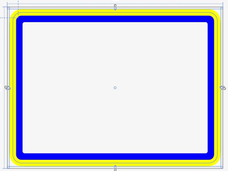
I focused on designing while keeping the print path in mind. It is one continuous curve that can be printed with only perimeters. No infill, no top layer, no bottom layer, no retractions. And no supports, either.

MatterControl slicer showing the design sliced as continuous curve.

I will need to print two of them.

Two copies of the design were printed, one for front and one for back.

The installation position doesn’t have to be exact, since the grille doesn’t seem to be covering anything in a particular pattern that would require that I keep the nearby holes clear. I think it should be OK to flow around these feet.

The two stands installed on Xbox One X, covering minimal cooling vent area.

The single loop design means the stand is not completely rigid but slightly flexible. The upside of this flexibility is that it will sit nicely on surfaces that are not perfectly flat. The downside of the flexibility is that the console may wobble a bit if bumped. Such is the tradeoff.

Xbox One X sitting on vertical stand.

Now my Xbox One X can stand vertically without completely blocking its cooling intakes. If someone wants to tinker with this design, the Onshape CAD file is a public document here. If someone wants to use the design as-is, it has been published to Thingiverse.

APC RBC Battery Module Teardown

I have a few UPS (Uninterruptible Power Supply) units to keep my electronics running through short blinks in household electricity, something more likely in a heat wave as neighborhood air conditioning units demand power from the grid. Historically I’ve preferred UPS made by APC as they’ve worked well for me, but over the past few years I’ve heard grumblings from unhappy APC users. The claim is that quality of their consumer line has gone down since their acquisition by Schneider Electric in a misguided effort to compete on price. I can confirm the price premium is less than it used to be, but it still exists. And as to the quality… all I can say is that my units are still working. I’ll post an update if any of the newer APC units fail.

I saw some of the complaints were of dead lead-acid batteries after some years, but I do not consider that a failure on APC’s part. Just like the lead-acid batteries in our cars, batteries are wear items expected to need replacement after some number of years. The guidelines for mission-critical UPS is to replace the battery modules after 2-3 years of active service, but that is being cautious. Batteries on long term standby (like those in a UPS) can last much longer. It’s just a matter of luck.

My luck ran out after five years, when my UPS started beeping at me with an error code. I bought the official replacement battery APCRBC123 (*) but I was curious: Superficially it appears to be two commodity 7Ah 12V modules connected together, are they actually that? Once the new module was installed and working, I took the old module outside to see if my suspicion was correct. The modules were held together by plastic sheets with adhesive backing, complete with convenient tabs where I could start peeling.

Once tape was removed (surprisingly cleanly) I could split the module apart and see it is indeed a pair of commodity form factor lead-acid batteries. Two of them, connected in series via a proprietary adapter in the middle.

So now I know: for the next replacement, it is possible to buy commodity batteries and rebuild the module myself. It wouldn’t have saved me much money this time: the APC module costs roughly in line with the average selling price of two 7Ah batteries. (*) Besides, who knows how long those zero review lowest-bidder batteries would last. But in a few years my new battery module will wear out and require another replacement. If there is a significant price premium on authentic APC replacement modules — or if they are no longer available at all — I have a fallback option.


(*) Disclosure: As an Amazon Associate I earn from qualifying purchases.

Virtual Lunar Rovers May Help Sawppy Rovers

Over a year ago I hand-waved a grandiose wish that robots should become smarter to compensate for their imperfections instead of chasing perfection with ever more expensive hardware. This was primarily motivated by a period of disillusionment as I wanted to make use of work by robotics research only to find that their published software tend to require hardware orders of magnitude more expensive than what’s feasible for my Sawppy.

Since then, I’ve noticed imperfection is something that’s coming up more and more frequently. I had my eyes on the DARPA Subterranean Challenge (SubT) for focusing researcher attention towards rugged imperfect environments. They’ve also provided a very promising looking set of tutorials for working with the ROS-based SubT infrastructure. This is a great resource on my to-do list.

Another interesting potential that I wasn’t previously aware of is NASA Space Robotics Phase 2 competition. While phase 1 is a simulation of a humanoid robot on Mars, phase 2 is about simulated rovers on the moon. And just like SubT, there will be challenges with perception making sense of rugged environments and virtual robots trying to navigate their way through. Slippery uneven surfaces, unreliable wheel odometry, all the challenges Sawppy has to deal with in real life.

And good news, at least some of the participants in this challenge are neither big bucks corporations nor secretive “let me publish it first” researchers. One of them, Rud Merriam, is asking questions on ROS Discourse and, even more usefully for me, breaking down the field jargon to language outsiders can understand on his blog. If all goes well, there’ll be findings here useful for Sawppy here on earth! This should be fun to watch.

Micro-ROS Now Supports ESP32

When I looked wistfully at rosserial and how it doesn’t seem to have a future in the world of ROS2, I mentioned micro-ROS appeared to be the spiritual successor but it required more powerful microcontrollers leaving the classic 8-bit chips behind. Micro-ROS doesn’t quite put microcontrollers on a ROS2 system as a first-class peer to other software nodes running on the computer, as there still needs to be a corresponding “agent” node on the computer to act as proxy. But it comes closer than rosserial ever tried to be, and looks great on paper.

Based on the micro-ROS architectural overview diagram, I understand it can support multiple independent software components running in parallel on a microcontroller. This is a boost in capability from rosserial which can only focus on a single task. However, it’s not yet clear to me whether a robot with a microcontroller running micro-ROS can function independent of a computer running full fledged ROS2. On a robot with ROS using rosserial, there still needs to be a computer running the ROS master among other foundational features. Are there similar requirements for a robot with micro-ROS?

I suppose I wouldn’t really know until I set aside the time to dig into it, which has yet to happen. But the likelihood just increased. I knew that the official support for micro-ROS started with various ARM Cortex boards, but reading the system requirements I saw nothing that would have prevented the non-ARM ESP32 from joining the group. Especially since it is a popular piece of hardware and it already runs FreeRTOS by default. I have a few modules already on hand and I expected it was only a matter of time before someone ported micro-ROS to the ESP32. Likely before I build up the expertise and find the time to try it myself.

That expectation was correct! A few days ago an announcement was posted to ROS Discourse that ESP32 is now officially part of the micro-ROS ecosystem. And thus another barrier against ROS2 adoption has been removed.

Fun with C# Strings: Interpolation and Verbatim

Relating to my adventures exploring iconography, this UWP application exercise also managed to add some novelty to a foundational concept: strings. Strings of characters to represent human readable text is a basic part of computer programming. Our very first “Hello World” program would use them… for the “Hello World” is itself a string! Even if someone learning programming had not yet covered the concept of strings, they use it right from the start. As such a fundamental building block, I had no reason to expect to find anything interesting or novel when I wrote C# code. It looks like C, so I assumed all strings behaved like C.

I was surprised to learn my assumption was wrong: there are some little handy syntactic shortcuts available in a C# program. Nothing that can’t be done some other way in the language and certainly nothing earth shattering, but nifty little tools all the same. I was most fascinated by the special characters.

The first one is $, the string interpolation prefix. I first came across it in a sample program that made generating some text output more succinct. It allows us to put variable names inline with the text and some tool in the compilation chain will handle the details of interpreting variable values as text and build the string for display. It definitely made the sample code easier to read, and can be nice in my own programs as well. It made code for my own simple logger easier to read. There is some minor security concern here as automatic interpolation risk introducing unexpected behavior, but at least for small play projects I’m not concerned.

The other special character is @, call the verbatim identifier. It disables almost all string processing for escape sequences, making it easy to use strings that have file paths: we no longer need to worry about the slashes accidentally becoming an escape character. It’s not something terribly common in my projects, but I do have to deal with paths and when I do so in C# this is going to reduce a lot of annoyance. And in direct contrast to interpolation, verbatim may actually cut down on security attack surface by making sure nothing unexpected can occur with escape sequences by eliminating the behavior completely. More tools in the toolbox is always good.

Icon Fun with Segoe MDL2

For my recently completed test program, I wanted arrows to indicate motion along X/Y/Z axis. I also wanted a nice icon to indicate the button for homing operations, plus a few other practical iconography. Thankfully they are easily available to UWP applications via Segoe MDL2.

One of the deepest memories from my early exposure to a graphical desktop environment is the novelty of vector fonts. And more specifically, fonts that are filled with fun decorative elements like dingbat. I remember a time when such vector fonts were intellectual property that need to be purchased like software, so without a business need, I couldn’t justify buying my own novelty font.

The first one I had impression of being freely available and didn’t quickly disappear was Webdings, a font that Microsoft started bundling with Windows sometime around the Windows 98 timeframe. I no longer remember if earlier versions of Windows come bundled with their own novelty fonts, but I have fond memories of spending far too much time scrolling through my Webdings options.

Times have moved on, and so have typefaces and iconography. For their UWP application platform, Microsoft provided an accompanying resource for Fluent Design icons called Segoe MDL2. And again, I had a lot of fun scrolling through that page to see my options.

I was initially surprised to see many battery icons, but in hindsight it made sense as something important for creating UI on portable computing devices. There were several variants for battery styline. Including vertical and horizontal orientations and charging, not charging, or battery saver. And each style had ten levels to indicate battery level 10% apart. Some of the code point layouts were a little odd. For example, Battery0 (0xE850) through Battery9 (0xE859) were adjacent to each other, but a full Battery10 was some distance away at 0xE83F. I don’t know why, but it adds an unnecessary step to convert a battery percentage value to a corresponding icon in Segoe MDL2.

The one that made me laugh out loud? 0xEBE8, a bug.

First Project Prototype Has Poor Precision

I’ve been bringing pieces together to build a machine to take distance measurements visually, with the primary motivation of measuring dimensions of circuit board features. Mechanically the machine is the three-axis motion control of a retired 3D printer, with a webcam sitting where the print nozzle used to be. It is controlled from a PC attached via USB, running software that I wrote as an exercise to learn UWP development. Once I figured out enough of UWP layout engine, I could put some user interface controls and take the thing on its first test drive.

Verdict: The idea has promise, but this first draft implementation is a bucket of fail.

For the first test, I taped a Digi-Key PCB ruler onto the Y-axis carriage where the print bed used to be installed. The ruler has clearly labeled dimensions on board representative of components on a circuit board. The first and easiest test is to make sure my movement distances match the ruler distance and this machine flunked its first test.

I have added a little circle in the middle of the camera field of view to serve as reference. I placed that circle at the 10 cm mark and commanded a move of 1 cm along the negative X axis. I expect the little circle to sit above the 9 cm mark as a result, but it is actually sitting at roughly 8.95 cm, a distance of 1.05 cm and roughly 5% longer than expected.

Camera control test 8.95mm

The first hypothesis is that this is an effect of the camera’s USB cable tugging on the camera as the print carriage moved, changing the viewing angle. It is, after all, merely held by tape on this first draft. So I repeated the experiment along the Y axis, which does not move the camera carriage and would eliminate flexible tape as a variable. Again I see a 5-6% overshoot.

When two measurement tools disagree, bring in a third opinion to break the tie. I pulled out my digital caliper and measured the ruler markings and they match, indicating the problem is indeed with the printer mechanicals. For whatever reason, this motion control carriage is moving further than commanded. Perhaps the belts had stretched out? Whatever the reason, this behavior could very well be why the printer was retired. I think I can compensate by changing the steps-per-millimeter setting in printer firmware, all I need is a precise measurement of actual movement.

Which brings up the other half of my problem: I can only get plus or minus half a millimeter precision with this webcam configuration. I can’t bring the camera any closer to the workpiece, because this webcam’s autofocus fails to focus at such close ranges.

I see two paths forward to address the optical precision shortcomings:

  1. Use another camera, such as a “USB microscope”. Most of the cheap ones are basically the electronics of a webcam paired with optics designed for short distance focus.
  2. Keep the camera but augment the optics with a clip-on macro lens. These are sold with the intent they let cell phone cameras focus on objects closer than they normally could.

Either should allow me to measure more accurately and tune the steps-per-millimeter value. While I contemplate my options, I went back into my UWP application to play around with a few other features.

Quick Notes on UWP Layout

Layout is another big can of worms in UWP application development, but having spent far too much time on keyboard navigation I’m postponing the big lessons until later. Today I’m going to learn just enough to get what I want on screen.

The first is controlling that shape I drew earlier. By default simple shapes (Ellipse, Rectangle, etc) dynamically adjusts to layout size, but there doesn’t seem to be a way to specify complex shapes that would be similarly dynamic. They are specified via X,Y coordinates and I didn’t find a way to specify “X is 25% of ActualWidth” in markup.

The fallback is to listen to SizeChanged event and recalculate coordinates based on ActualHeight and ActualWidth. I get my little camera preview overlay graphics on screen, but that’s only the start. I wanted to draw other on screen directional controls to augment the arrow keys.

While working to position the shape and on screen controls, I ran into a frustrating problem: there are two different ways to specify an on screen color for rendering. We have Windows.UI.Color and then we have an entirely different System.Drawing.Color. I’m sure there’s a good explanation on the history here, but right now it’s just annoying to have the “Color” class be ambiguous.

Rendering the user controls outside of camera got a tiny bit tricker, because now I have to track what happens when, including when an element is loaded for me to kick off other events relating to serial communication. Thanks to this Stack Overflow thread, I learned there are three different candidates depending on need. There’s Loaded, or LayoutUpdated, or SizeChanged. And people are constantly surprised when one of them does something unexpected, it seems like none of the three does exactly what people would want. This is just one of many parts making UWP layout confusing.

When I added controls by hand, they were fully adjacent to each other with no space in between them. I knew I needed to specify either a margin, or a padding, but couldn’t figure out which is which. I still don’t… they do slightly different things under different circumstances. To ensure elements inside a grid don’t butt up against each other, I have to use Padding. To ensure the video preview doesn’t butt up against edge of the window frame, I have to use Margin. I have yet to build an intuition on which is the right tool for the job, which I hope will come with practice.

But never mind little layout details… I have my G-code controlled camera, and I want to know if it works like I wanted. (Spoiler: it didn’t.)

Quick Notes on UWP Drawing

Because I wanted to handle keyboard events, I created an UserControl that packages the CaptureElement displaying the camera preview. Doing this allowed an easy solution to another problem I foresaw but didn’t immediately know how to solve: How do I draw reference marks over the camera preview? I’d definitely need something to mark the center, and maybe additional marks for horizontal/vertical alignment and if I’m ambitious, an on screen ruler to measure distance.

With an UserControl, drawing these things became trivial: I can include graphical drawing elements as a peer of CaptureElement in my UserControl template, and we are off to the races.

Or so I thought. It is more accurate to say I was off to an entirely different set of problems. The first was making marks legible regardless of camera image. That means I can’t just use a bright color, because that would blend in on a bright background. Likewise, a dark color would be lost in a dark background. What I need is a combination of high contrast colors to ensure they are visible independent of background characteristics. I had thought: easy! Draw two shapes with different stroke thickness. I first draw a rectangle with a thicker stroke, like this blue rectangle:

StrokeThickness24

I then drew a yellow rectangle with half the stroke thickness, expecting it to sit in the center of the blue stroke. But it didn’t! The yellow covered the outer half leaving the inner half, instead of my expectation of a yellow line with blue on either side. But even though this was unexpected, it was still acceptable because that gave me the contrasting colors I wanted.

StrokeThickness24and12

This only barely scratches the surface of UWP drawing capability, but I have what I need for today. I’ve spent far too much time on UWP keyboard navigation and I’m eager to move forward to make more progress. Drawing a single screen element is fun, but to be useful they need to coexist with other elements, which means layout comes into the picture.

User Interface Taking Control

Once I finally figured out that keyboard events require objects derived from UWP’s Control class, the rest was pretty easy. UWP has a large library of common controls to draw from, but none really fit what I’m trying to present to the user.

What came closest is a ScrollViewer, designed to present information that does not fit on screen and allows the user to scroll around the full extents much as my camera on a 3D printer carriage can move around the XY extents of the 3D printer. However, the rendering mechanism is different. ScrollViewer is designed to let me drop a large piece of content (example: a very large or high resolution image) into the application and let ScrollViewer handle the rest independently. But that’s not what I have here – in order for scrolling to be mirrored to physical motion of 3D printer carriage, I need to be involved in the process.

Lacking a suitable fit in the list of stock controls, I proceeded to build a simple custom control (based on the UserControl class) that is a composite of other existing elements, starting with the CaptureElement displaying the webcam preview. And unlike on CaptureElement, the OnKeyDown and OnKeyUp event handlers do get called when defined on a UserControl. We are in business!

Once called, I have the option to handle it, in this case translating directional desire into G-code to be sent to the 3D printer. My code behavior fits under the umbrella of “inner navigation”, where a control can take over keyboard navigation semantics inside its scope.

I also have the ability to define special keys inside my scope, called accelerators ([Control] + [some key]) or access ([Alt] + [some key]) keys. I won’t worry about it for this first pass, but they can be very powerful when well designed and a huge productivity booster for power users. They also have a big role in making an application keyboard accessible. Again while it is a very important topic for retail software, it’s one of the details I can afford to push aside for a quick prototype. But it’ll be interesting to dive in sometime in the future, it’s a whole topic in and of itself. There’s literally a book on it!

In the meantime, I have a custom UserControl and I want to draw some of my own graphics on screen.

My Problem Was One Of Control

For my computer-controlled camera project, I thought it would be good to let the user control position via arrow keys on the keyboard. My quick-and-dirty first attempt failed, so I dived into UWP documentation. After spending a lot of time reading about nuts and bolts of keyboard navigation, I finally found my problem and it’s one of the cases when the answer has been in my face the whole time.

When my key press event handlers failed to trigger, the first page I went to is the Keyboard Events page. This page has a lot of information up front and center about eligibility requirements to receive keyboard events, here’s an excerpt from the page:

For a control to receive input focus, it must be enabled, visible, and have IsTabStop and HitTestVisible property values of true. This is the default state for most controls.

My blindness was reading the word “control” in the general sense of a visual element on the page for user interaction. Which is why I kept overlooking the lesson it was trying to tell me: if I want keyboard events, I have to use something that is derived from the UWP Control object. In other words, not “control” in the generic language case but “Control” as a specific proper name in the object hierarchy. I would have been better informed about the distinction if they had capitalized Control, or linked to the page for the formal Control object, or any of a number other things to differentiate it as a specific term and not a generic word. But for whatever reason they chose not to, and I failed to comprehend the significance of the word again and again. It wasn’t until I was on the Keyboard Accessibility page did I see this requirement clearly and very specifically spelled out:

Only classes that derive from Control support focus and tab navigation.

The CaptureElement control (generic name) used in the UWP webcam example is not derived from Control (proper name) and that’s why I have not been receiving the keyboard events. Once I finally understood my mistake, it was easy to fix.

Tab and Arrow Keys Getting In Each Others Way

In a UWP application, we have two major ways for navigating UI controls using the keyboard: a linear path using Tab key (and shift-Tab to go backwards), and a two-dimensional system with the four arrow keys. A part of what makes learning UWP keyboard navigation difficult is the fact that these two methods are both active simultaneously and we have to think about what happens when an user switches between them.

Application authors can control tabbing order by setting TabIndex. It is also the starting point of keyboard navigation, since the initial focus is on the element with the highest TabIndex. Occasionally the author would want to exclude something from tabbing order, they could turn that off by setting IsTabStop to false. I thought that was pretty easy until I started reading about TabFocusNavigation. This is where I’m thankful for the animation illustrating the concept on this page or else I would have been completely lost.

On the arrow navigation side, XYFocusKeyboardNavigation is how authors can disable arrow navigation. But since it is far from a simple system, selectively disabling certain parts of the app would have wildly different effects than simple “on” or “off” due to how subtrees of controls interact. That got pretty confusing, and that’s even before we start trying to understand how to explicitly control the behavior of each arrow direction with the XY focus navigation strategies.

Even with all these complex options, I was skeptical they could cover all possible scenarios. And judging by the fact we have an entire page devoted to programmatic focus navigation, I guess they didn’t manage. When the UI designer wants something that just can’t be declared using existing mechanisms, the application developer has the option of writing code to wrangle keyboard focus.

But right now my problem isn’t keyboard navigation behaving differently from what I wanted… the problem is that I don’t see keyboard events at all. My answer was elsewhere: I had no control, in both senses of the word.

Scott Locklin’s Take on Robotics

As someone who writes about robots on WordPress, I am frequently shown what other people have written about robots on WordPress. Like this post titled “Open problems in Robotics” by Scott Licklin and I agree with his conclusion: state of the art robotics still struggle to perform tasks that an average one year old human child can do with ease.

He is honest with a disclaimer that he is not a Serious Robotics Researcher, merely a technically competent spectator taking a quick survey of the current state of the art. That’s pretty much the same position I am in, and I agree with his list of big problems that are known and generally unsolved. But more importantly, he was able to explain these unsolved problems in generally understandable terms and not fall into field jargon as longtime practitioners (or wanna-be posers like myself) would be tempted to do. If someone not well versed in the field is curious to see how a new perspective might be able to contribute, Scott’s list is not a bad place to start. Robotics research still has a ton of room for newcomers to bring new ideas and new solutions.

Another important aspect of Scott’s writing is making it clear that unsolved does not mean unsolvable, a tone I see all too frequently from naysayers claiming robotics research is doomed to failure and a waste of time and money. Robotics research has certainly been time consuming and expensive, but I think it’s a stretch to say it’ll stay that way forever.

However, Scott is pessimistic that algorithms running on computers as we know them today would ever solve these problems, hypothesizing that robots would not be successful until they take a different approach to cognition. “more like a simulacrum of a simple nervous system than writing python code in ROS” and here our opinions differ. I agree current computing systems built on silicon aren’t able to duplicate brains built on proteins, but I don’t agree that is a requirement for success.

We have many examples in our daily lives where a human invention works nothing like their natural world inspiration, but have been proven useful regardless of that dissimilarity. Hydraulic cylinders are nothing like muscles, bearings and shafts are nothing like joints, and a Boeing 747 flies nothing like an eagle. I believe robots can effectively operate in our world without having brains that think the way human brains do.

But hey, what do I know? I’m not a big shot researcher, either. So the most honest thing to do is to end my WordPress post here with the exact same words Scott did:

But really, all I know about robotics is that it’s pretty difficult.

Randomized Dungeon Crawling Levels for Robots

I’ve spent more time than I should have on Diablo III, a video game where our hero adventures through endless series of challenges. Each level in the game has a randomly generated layout so it’s not possible to memorize where the most rewarding monsters live or where the best treasures are hidden. This keeps the game interesting because every level is an exploration in an environment I’ve never seen before and will never see its exact duplicate again.

This is what came to my mind when I learned of WorldForge, a new feature of AWS RoboMaker. For those who don’t know: RoboMaker is an AWS offering built around ROS (Robot Operating System) that lets robot builders leverage the advantages of AWS. One example most closely relevant to WorldForge is the ability to run multiple virtual robot simulations in parallel across a large number of AWS machines. It’ll cost money, of course, but less than buying a large number of actual physical computers to run those simulations.

But running a lot of simulations isn’t very useful whey they are all running the same robot through the same test environment, and this is where WorldForge comes in. It’s a tool that accepts a set of parameters, then generate a set of simulation worlds that randomly place or replace features according to those given parameters. Then virtual robots can be set loose to do their thing across AWS machines running in parallel. Consistent successful completion across different environments builds confidence our robot logic is properly generalized and not just memorizing where the best treasures are buried. So basically, a randomized dungeon crawler adventure for virtual robots.

WorldForge launched with ability to generate randomized residential environments, useful for testing robots intended for home use. To broaden the appeal of WorldForge, other types of environments are coming in the future. So robots won’t get bored with the residential tileset, they’ll also get industrial and business tilesets and more to come.

I hope they appreciate the effort to keep their games interesting.

Learning UWP Keyboard Navigation

After a quick review of the of UWP keyboard event basics, I opened up the can of worms that is keyboard navigation. I stumbled into this because I wanted to use arrow keys to move the 3D printer carriage holding a camera, but arrow keys already have roles in an application framework! My first effort to respond to arrow keys was a failure, and I hypothesized that my code conflicted with existing mechanisms for arrow keys. In order to figure out how I can write arrow key handlers that coexist with existing mechanisms, I must first learn what they are.

Graphical user interfaces are optimized for pointing devices like a mouse, stylus, or touchscreen. But that’s not always available, and so the user needs to be able to move around on screen with the keyboard. Hence the thick book of rules that is summarized by the UWP focus navigation page. As far as I can tell, it is an effort to put together all the ways arrow keys were used to move things around on screen. A lot of these things are conventions that we’ve become familiar with without really thinking about it as a rigorous system of rules, many were developed by application authors so it “felt right” for their specific application. It reminds me of the English language: native speakers have an intuitive sense of the rules, but trying to write down those rules is hard. More often than not, the resulting rules make no sense when we just read the words.

And, sadly, I think the exact same thing happened in the world of keyboard navigation. But in a tiny bit of good news, we’re not dependent on understanding words, this page also had a lot of animated graphics to illustrate how keyboard navigation functions under different scenarios. I can’t say it makes intuitive sense, but at least seeing the graphics help understand the intent being described. It’s especially helpful in scenarios where tab navigation interacts with arrow key navigation.

Reviewing UWP Keyboard Routed Events

I wanted to have keyboard control of the 3D printer carriage, moving the webcam view by pressing arrow keys. I knew enough about the application framework to know I needed to implement handlers for the KeyDown and KeyUp events, but in my first implementation those handlers are never called.

If at first I don’t succeed, it’s time to go to the manual.

The first stop is the overview for UWP Events and Routed Events, the umbrella of event processing architecture including keyboard events. It was an useful review and I was glad I hadn’t forgotten anything fundamental or have missed anything significantly new.

Next stop was the UI design document for keyboard interactions. Again this was technically a review, but I’ve forgotten much of this information. Keyboard handling is complicated! It’s not just an array of buttons, there are a lot of interactions between keys and conventions build up over decades as to what computer literate users have come to expect.

When I think of key interactions, my first reaction is to think about the shift key and control key. These modifier keys change the meaning of another button: the difference between lowercase ‘c’, uppercase ‘C’ and Control+C which might be anything from “interrupt command line program” to “Copy to clipboard.”

But that’s not important to my current project. My desire to move the camera carriage using arrow keys opened up an entirely different can of worms: keyboard navigation.

Webcam Test with UWP

Once I had an old webcam taped to the carriage of a retired 3D printer, I shifted focus to writing code to coordinate the electronic and mechanical bits. My most recent experiments in application development were in the Microsoft UWP platform, so I’m going to continue that momentum until I find a good reason to switch to something else.

Microsoft’s development documentation site quickly pointed me to an example that implements a simple camera preview control. It looks like the intent here is to put up a low resolution preview so the user can frame the camera prior to taking a high resolution still image. This should suffice as a starting point.

In order to gain access to the camera feed, my application must declare the webcam capability. This will show the user a dialog box that the application wants to access the camera with options to approve or deny, and the user must approve before I could get video. Confusingly, that was not enough. If I approve camera access I still see errors. It turns out that even though I didn’t care about audio, I had to request access for the microphone as well. This seems like a bug but a simple enough workaround in the short term.

Once that was in place, I got a low resolution video feed from the camera. I don’t see any way to adjust parameters of this live video. I would like to shift to a higher resolution and I’m willing to accept lower frame rate. I would also like to reduce noise and I’m willing to accept lower brightness. The closest thing I found to camera options is something called “camera profiles“. For the moment this is a moot point because when I queried for profiles on this camera, IsVideoProfileSupported returned false.

I imagine there is another code path to obtain video feed, used by video conference applications and video recording apps. There must be a way to select different resolutions and adjust other parameters, but I have a basic feed now so I’m content to put that on the TO-DO list and move on.

The next desire is ability to select a different camera, since laptops usually have a built-in camera and I would attach another via USB. Thanks to this thread on Stack Overflow, I found a way to do so by setting VideoDeviceId property of MediaCaptureInitializationSettings.

And yay, I have a video feed! Now I want to move the 3D printer carriage by pressing the arrow keys. I created keyboard event handlers KeyDown and KeyUp for my application, but the handlers were never called. My effort to understand this problem became the entry point for a deep rabbit hole into the world of keyboard events in UWP.

[Code for this exploration is public on Github.]

And I Ended Up Using Tape

Now I feel ridiculous. After spending time disassembling a HP HD 4310 webcam to see how to best modify it for mounting on the carriage of my retired 3D printer chassis… I realized the fastest and easiest way to test some ideas is to just tape the thing to the carriage with good old reliable blue painter’s tape.

The tape would not be sturdy enough for precision measurements, of course, but that’s not important on the first pass through. I needed to see if the camera can autofocus within the range I want, and I need to see the quality of images I can get with this camera. And most of all, I need to verify I could write the code necessary to control everything working together as a unit. None of that need a rigid mounting.

Right now the biggest problem is the USB cable exerting a force as the carriage moves around. It is a pretty soft cable, but strong enough to wiggle a taped-down camera. I suspect any kind of 3D printed bracket would be enough to resist the force exerted by the USB cable.

In the short term, this is not a huge problem. Tape on the left and right sides of the camera has good leverage to resist the cable as the carriage moves along the X axis, and Y-axis movements would not exert any force at all since it is an independent assembly.

So a little blue tape is all I need right now to let me get started on the coding.

Mild HP HD 4310 Webcam Integration Modification

I took a HP HD 4310 webcam apart to see inside. Mainly out of curiosity and for fun, but also to check out my options for system integration. Webcams generally come with some kind of mechanism that helps them perch on top of a wide variety of surfaces, ranging from flat tabletop to the narrow bevel of a computer monitor. One thing they are not designed for, however, is to be rigidly mounted to a 3D printer chassis. Some webcam bases have integrated a standard 1/4″-20 camera tripod mount, but the HP HD 4310 is not one of them.

The built in base on a HD 4310 can unfold to sit flat on a surface, or grasp a computer monitor. In my intended usage, however, it is not useful and gets in the way. Fortunately, once we take the case apart we could access the single screw necessary to remove the base.

I considered designing and 3D printing something to slot in the exact same position as the base, but it is small and the single attachment point is difficult to ensure rigidity. (A problem in its normal usage as a webcam as well.) I think it is more likely for me to remove the two short case screws and replace them with longer screws. This allows attachment to a much wider and therefore more stable bracket.

I was also concerned about inadvertent button presses launching functions unexpectedly. I don’t plan to use the buttons so I had planned to cut some traces on the circuit board to disable those buttons. Fortunately, the physical buttons can be removed to eliminate inadvertent activation.

These mild modifications should be enough to help me get started. If I want to go further, there’s the option to host the circuit board in a new enclosure. The main obstacle here is the USB data cable: its hard rubber protective strain relief bushing on the back shell has been installed very tightly. I suspect it could not be removed without destroying the back shell, the cable, or possibly both. The other option is to cut the wires and build my own USB data cable, but I’m not willing to put in that much effort for an early first draft prototype. In fact, I probably shouldn’t have put in the amount of effort I already have.

HP Webcam HD 4310 Teardown

Since there’s currently a shortage of high quality webcams, an old and long discontinued HD 4310 has been repurposed for the current exploration. The fact it is not brand new also makes it less psychologically intimidating to tailor the device to suit. Since there’s no warranty left to worry about voiding, I’m going to open it up to see what I have to work with.

The two black circular depressions in the back were stickers, easily taken off to access screws underneath. Once the screws were gone, the plastic enclosure proved to be two pieces of plastic held by clips and could be pried apart with mild effort.

When the two halves popped apart, the buttons flew out as well. Though the three buttons are individually rigid, they are held together by a flexible strip. On the back shell, we could see a single screw holding the webcam stand in place. The stand slid out easily when that lone screw was removed.

Everything else seems to be mounted to a single circuit board, which was expected. Except for the single microphone, which was a mild surprise. The front exterior shape had two perforated grills that implied a pair of microphones. Also, I had expected those two microphones to be surface mounted to the circuit board, so it was a surprise to see only a single microphone that was not surface mount. It wasn’t even aligned with the perforated grill! I thought that would compromise sound quality, but I’m no audio engineer.

The circuit board was held by two more screws. Before I took them off, I considered the possibility that the front shell was part of the optical assembly. There’s a risk that when I pick up the camera I’ll scatter little lens mechanisms all over my work table. If this was a brand new unit I might have backed off, but it wasn’t, so I proceeded.

Fortunately the camera and lens assembly was an integrated unit and nothing flew out as the buttons did earlier. Once removed we could see the audio guide sending sound from one small part of the perforated front grill to the microphone. We could also see the three buttons up top, and the connector for USB.

Armed with knowledge of what’s inside its plastic enclosure, I can come up with a plan on how to integrate this peripheral into a project.