Hello ESPAsyncWebServer

I have several interesting sensors in my hardware to-do pile, and I think it’d be interesting to do a series of interactive UIs one for each sensor. My first effort in this vein was a browser UI to interactively play with an AS7341 spectral color sensor, and I learned a lot doing it.

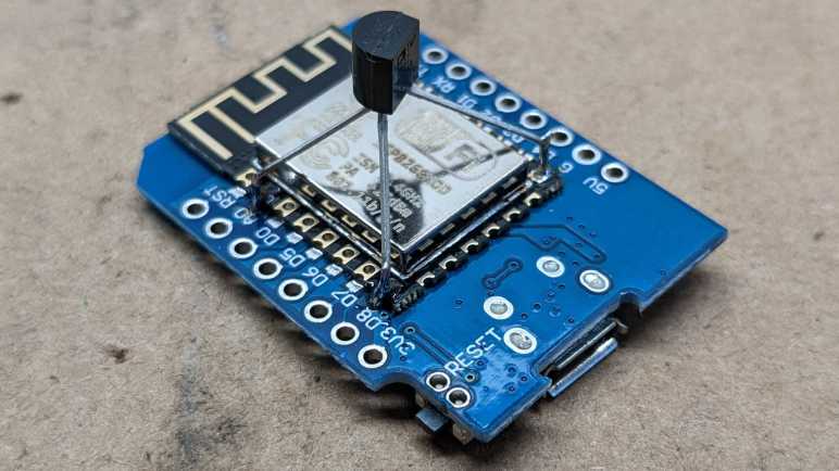
One lesson was that I could perform all sensor data computation and visualization in the browser, so I don’t need much in the way of microcontroller capabilities. The ESP32 I used for AS7341 web UI was overkill. All I needed was an I2C bus and WiFi, so I could easily drop down to an ESP8266. However, because I had used the WebServer from ESP32 Arduino Core library, I will need an ESP8266-friendly replacement.

Sticking with Original Repository

I decided to look into ESPAsyncWebServer, which I had been using indirectly as a dependency of ESPHome. In addition to supporting ESP8266 as well as ESP32, it had a few other features I liked. The most important being its ability to serve files from flash file system, so I don’t have to do silly things like hexadecimal encoding files to program memory. Using this capability also means switching from Arduino IDE to PlatformIO, because the latter has easy tools to work with flash file system. And finally, I was intrigued by the claim ESPAsyncWebServer can serve GZip-compressed files. Making better use of our precious megabyte of flash memory.

The only worry is that the GitHub repository looks stale. There are over 100 open issues, and there are 69 pull requests sitting unmerged. Maybe I should use one of the forks that saw more recent development? Since I was introduced via ESPHome, I thought I would try their fork of the repository. It has seen more recent work, but unfortunately as of this writing, the most recent merge has a C syntax error.

.pio\libdeps\d1_mini\ESPAsyncWebServer-esphome\src\AsyncWebSocket.cpp: In function 'size_t webSocketSendFrame(AsyncClient*, bool, uint8_t, bool, uint8_t*, size_t)':
.pio\libdeps\d1_mini\ESPAsyncWebServer-esphome\src\AsyncWebSocket.cpp:105:23: error: expected primary-expression before ')' token
  105 |   if (!client->send();) return 0;
      |                       ^

It’s been sitting broken for over a month now. I don’t know the story behind the scenes, but it is clear the repository is in no shape to be used. I don’t know which of the other forks might be worth investigating. As an introduction, I’ll start with the original until I run into a compelling reason to do otherwise.

SPIFFS vs. LittleFS

There were a few examples to help me orient myself with ESPAsyncWebServer. Compiling them myself, though, brought up warnings that SPIFFS is now deprecated and I should switch to LittleFS. This was opened as an issue #780 against ESPAsyncWebServer library, but was closed without further action because the warning came from an optional SPIFFS-specific component called SPIFFSEditor. Since it is optional and not relevant to my projects, I can choose to ignore the warning.

Switching over is a little tricky because we build the code and file system separately, and they are two different uploads. If I upload the file system first, it gets reformatted by the code when it sees a file system it doesn’t recognize. As per documentation: “attempting to mount a SPIFFS volume under LittleFS may result in a format operation and definitely will not preserve any files, and vice-versa” In order to end up with a functional system, I need upload code using LittleFS then upload LittleFS file system contents.

Gzip Compressed Files

After verifying a simple “Hello World” web server worked, I compressed the small index.html into index.html.gz. Uploading the new LittleFS system, I was happy to see it come up in my browser! But how does this work? I queried using curl and found the answer:

HTTP/1.1 200 OK
Content-Length: 1284
Content-Type: text/html
Content-Encoding: gzip
Content-Disposition: inline; filename="index.html"
Connection: close
Accept-Ranges: none

ESPAsyncWebServer added “Content-Encoding: gzip” to the HTTP header effectively making the browser deal with it. As the browser will be running on a far more powerful CPU than the ESP8266, it is indeed better suited to handle decompression.

Serve Angular Web Application

As a test of compression, I brought over my Angular tutorial app “Tour of Heroes”. It’s not as simple as just copying the files, though. As per Angular deployment guide, I needed to add a rule so ESPAsyncWebServer will serve up index.html rather than a 404 error when an URL is not found.

  server.onNotFound([](AsyncWebServerRequest *request){
    request->send(LittleFS, "/www/index.html");
  });

Another problem was that LittleFS has a 31-character name limit. (32 characters + null termination.) Unfortunately, my Angular app bundle had a file polyfills.716cc9a230a87077.js.gz which is 32 letters! The hexadecimal hash was generated by “–output-hashing” option of “ng build”. It’s changed on every build in order to avoid using stale cached versions of polyfills.js. I could skip that feature, but then I run the risk of stale cached files. The other workaround is to skip compressing polyfills.js. Dropping the “.gz” extension resulted in a 29-letter filename that works for LittleFS.

With all files in my Angular app compressed (except for polyfills.716cc9a230a87077.js) the size of the app dropped from ~800kB down to ~230kB. This is a dramatic difference when default available flash storage is only 1MB out of a total of 4MB total flash memory onboard.

Should I use Angular to build my ESP8266-hosted sensor web UI projects? No. It is far too heavyweight and a simple sensor UI does not need the capabilities of Angular application framework.

Will I use Angular to build my ESP8266-hosted sensor web UI projects? Possibly. Angular is not the best tool for the job, but it might be valuable for me to practice Angular by starting with something simple.


Source code for this exploratory project is publicly available on GitHub

Adafruit SSD1305 Arduino Library on ESP8266

Thanks to Adafruit publishing an Arduino library for interfacing with SSD1305 display driver chip, I proved that it’s possible to control an OLED dot matrix display from a broken FormLabs Form 1+ laser resin 3D printer. But the process wasn’t seamless, I ran into several problems using this library:

  1. Failed to run on ESP32 Arduino Core due to watchdog timer reset.
  2. 4 pixel horizontal offset when set to 128×32 resolution.
  3. Sketch runs only once on Arduino Nano 33 BLE Sense, immediately after uploading.

Since Adafruit published the source code for this library, I thought I’d take a look to see if anything might explain any of these problems. For the first problem of watchdog reset on ESP32, I found a comment block where the author notes potential problems with watchdog timers. It sounds like an ESP8266 is a platform known to work, so I should try that.

  // ESP8266 needs a periodic yield() call to avoid watchdog reset.
  // With the limited size of SSD1305 displays, and the fast bitrate
  // being used (1 MHz or more), I think one yield() immediately before
  // a screen write and one immediately after should cover it.  But if
  // not, if this becomes a problem, yields() might be added in the
  // 32-byte transfer condition below.

While I’m setting up an ESP8266, I could also try to address the horizontal offset. It seems a column offset of four pixels were deliberately added for 32-pixel tall displays, something not done for 64-pixel tall displays.

  if (HEIGHT == 32) {
    page_offset = 4;
    column_offset = 4;
    if (!oled_commandList(init_128x32, sizeof(init_128x32))) {
      return false;
    }
  } else {
    // 128x64 high
    page_offset = 0;
    if (!oled_commandList(init_128x64, sizeof(init_128x64))) {
      return false;
    }
  }

There was no comment to explain why this line of code was here. My best guess is the relevant Adafruit product has internally wired its columns with four pixels of offset, so this code makes a shift to compensate. If I remove this line of code and rebuild, my OLED displays correctly.

As for the final problem of running just once (immediately after upload) on an Arduino Nano 33 BLE Sense, I don’t have any hypothesis. My ESP8266 happily restarted this test sketch whenever I pressed the reset button or power cycled the system. I’m going to chalk it up to a hardware-specific issue with the Arduino Nano 33 BLE Sense board. At the moment I have no knowledge (and probably no equipment and definitely no motivation) for more in-depth debugging of its nRF52840 chip or Arm Mbed OS.

Now I have this OLED working well with an ESP8266, a hardware platform I have on hand, I can confidently describe this display module’s pinout.

Fan Strobe LED Adjustments via ESPHome

After proving my fan blade LED strobe idea worked with a minimalist Arduino sketch, I ported that code over as an ESPHome custom component. I thought it would be good practice for writing ESPHome custom components and gain Home Assistant benefit of adding adjustments in software. For me it was easier to create an analog control with a few lines of YAML and C, than it would be to wire up a potentiometer. (I recognize it may be the reverse for people more comfortable with hardware than software.)

The first adjustment “Fan Speed Control” actually did not require custom component at all: making the fan speed adjustable utilized the built-in fan speed component. In my minimalist sketch the fan is always running at full speed, now I can adjust fan speed and verify that the strobe logic indeed stays in sync with the fan speed. Meaning the strobe keeps these fan blades visually frozen in the same place regardless of their rotational speed.

The first custom output component adjustment “Strobe Duration” changes the duration of LED strobe pulse, from zero to 1000 microseconds. For this LED array, I found values under 100 to be too dim to be useful. The dimmest usable value is around 100, and things seem to work well up to 300. I start detecting motion blur above 300, and things are pretty smeared out above 600.

The next addition is a toggle switch “Strobe Tachometer Toggle”. Because the tachometer signal pulses twice per revolution, I ignore every other pulse. But that means a 50% chance the code will choose to trigger on the wrong pulse, resulting in a visually upside-down image. When this happens, this toggle allows us to flip to trigger on the opposing pulse, flipping the frozen visual right-side up.

The final custom component adjustment “Strobe Delay” adds a delay between triggered by tachometer wire and illumination of LED strobe. This changes the point at which the fan is visually frozen by the strobe light. Dynamically adjusting this value makes it look like the fan blade is slowly rotating position even though it is actually rotating at ~1200RPM. I think it is a fun effect, but to fully take advantage of that effect I will need longer delays, which means finding how I could move that work outside of my interrupt service routine. Inside the ISR I should set up a hardware timer for this delay and turn on LED when timer expires. I can then use the same mechanism to set a timer for LED duration and turn off LED when that timer expires.

Unfortunately, there are only two hardware timers on an ESP8266, and they are both spoken for. One runs WiFi, the other runs Arduino core for things like millis(). To explore this idea further, I will need to move up to an ESP32 which has additional hardware timers exposed to its Arduino core. And if I choose to explore that path, I don’t even need to redo my circuit board: there exists a (mostly) drop-in ESP32 upgrade for anything that runs a Wemos D1 Mini.


YAML Excerpt:

esphome:
  includes:
    - led_strobe_component.h

output:
  - platform: esp8266_pwm
    pin: 14
    id: fan_pwm_output
    frequency: 1000 Hz
  - platform: custom
    type: float
    lambda: |-
      auto led_strobe = new LEDStrobeComponent();
      App.register_component(led_strobe);
      return {led_strobe};
    outputs:
      id: strobe_duration_output
  - platform: custom
    type: float
    lambda: |-
      auto led_strobe_delay = new LEDStrobeDelayComponent();
      App.register_component(led_strobe_delay);
      return {led_strobe_delay};
    outputs:
      id: strobe_delay_output

fan:
  - platform: speed
    output: fan_pwm_output
    id: fan_speed
    name: "Fan Speed Control"

light:
  - platform: monochromatic
    output: strobe_duration_output
    id: strobe_duration
    name: "Strobe Duration"
    gamma_correct: 1.0
  - platform: monochromatic
    output: strobe_delay_output
    id: strobe_delay
    name: "Strobe Delay"
    gamma_correct: 1.0

switch:
  - platform: custom
    lambda: |-
      auto even_odd_flip = new LEDStrobeEvenOddComponent();
      App.register_component(even_odd_flip);
      return {even_odd_flip};
    switches:
      name: "Strobe Tachometer Toggle"

ESPHome custom component file led_strobe_component.h:

#include "esphome.h"

volatile int evenOdd;
volatile int strobeDuration;
volatile int strobeDelay;

IRAM_ATTR void tach_pulse_handler() {
  if (0 == evenOdd) {
    evenOdd = 1;
  } else {
    delayMicroseconds(strobeDelay);
    digitalWrite(13, HIGH);
    delayMicroseconds(strobeDuration);
    digitalWrite(13, LOW);
    evenOdd = 0;
  }
}

class LEDStrobeComponent : public Component, public FloatOutput {
  public:
    void setup() override {
      // LED power transistor starts OFF, which is LOW
      pinMode(13, OUTPUT);
      digitalWrite(13, LOW);

      // Attach interrupt to tachometer wire
      pinMode(12, INPUT_PULLUP);
      evenOdd = 0;
      attachInterrupt(digitalPinToInterrupt(12), tach_pulse_handler, RISING);

      strobeDuration = 200;
    }

    void loop() override {
    }

    void write_state(float state) override {
      // Multiply by 1000 = strobe duration from 0 to 1ms.
      strobeDuration = 1000 * state;
    }
};

class LEDStrobeEvenOddComponent: public Component, public Switch {
  public:
    void write_state(bool state) override {
      evenOdd = !evenOdd;
      publish_state(state);
    }
};

class LEDStrobeDelayComponent: public Component, public FloatOutput {
  public:
    void write_state(float state) override {
      strobeDelay = 1000*state;
    }
};

LED Strobing to Fan Speed Signal

The reason I cared about power-on response time of a salvaged LED array is because I wanted to use it as a strobe light shining on a cooling fan pulsing once per revolution. Historically strobe lights used xenon bulbs for their fast response, as normal incandescent bulbs were too slow. This LED array used to be a battery-powered work light with no concern of reaction time, but LEDs are naturally faster than incandescent. Is it fast enough for the job? PC case fan specifications usually range from the hundreds to low thousands of RPM. Using 1200RPM as a convenient example, that means 1200/60 seconds per minute = 20 revolutions per second. Pulsing at 20Hz should be easy for any LED.

For the hardware side of controlling LED flashes, I used a 2N2222A transistor because I had a bulk bag of them. They are usually good for switching up to 0.8 Amps of current. I measured this LED array and it drew roughly 0.3 Amps at 11.3V, comfortably within limits. I just need to connect this transistor’s base to a microcontroller to toggle this light on and off. For this experiment I repurposed the board I had built for the first version of my bedstand fan project. I unsoldered the TMP36 sensor to free up space for 2N2222A and associated LED power wire connector.

This board also had the convenience of an already-connected fan tachometer wire. My earlier project used it for its original purpose of counting fan RPM, but now I will use those pulses to trigger a LED flash. Since timing is critical, I can’t just poll that signal wire and need a hardware interrupt instead. Within Arduino framework I could use attachInterrupt() for this purpose and run a small bit of code on every tachometer wire signal pulse. Using an ESP8266 for this job had an upside and a downside. The upside is that interrupts could be attached to any available GPIO pin, I’m not limited to specific pins like I would have been with an ATmega328P. The downside is that I have to use an architecture-specific keyword IRAM_ATTR to ensure this code lives in the correct part of memory, something not necessary for an ATmega328P.

Because it runs in a timing-critical state, ISR code is restricted in what it can call. ISR should do just what they absolutely need to do at that time, and exit allowing normal code to resume. So many time-related things like millis() and delay() won’t work as they normally would. Fortunately delayMicroseconds() can be used to control duration of each LED pulse, even though I’m not supposed to dawdle inside an ISR. Just for experiment’s sake, though, I’ll pause things just a bit. My understanding of documentation is as long as I keep the delay well under 1 millisecond (1000 microseconds) nothing else should be overly starved for CPU time. Which was enough for this quick experiment, because I started noticing motion blur if I keep the LED illuminated for more than ~750 microseconds. The ideal tradeoff between “too dim” and “motion blurred” seems to be around 250 microseconds for me. This tradeoff will be different for every different combination of fan, circuit, LED, and ambient light.

My minimalist Arduino sketch for this experiment (using delayMicroseconds() against best practices) is publicly available on GitHub, as fan_tach_led within my ESP8266Tests repository. Next step in this project is to move it over to ESPHome for bells and whistles.

First Run with DS18B20 Temperature Sensor

I have a revised bedside fan (now with integrated LED illumination) up and running, and now it needs a temperature sensor. The goal is so I could automate turning off the fan once things cool down. My previous attempt used a TMP36 sensor that reported results as an analog voltage level. The results made me feel it was not a good fit with ESP8266 ADC peripheral. I don’t blame Espressif, it’s just a matter of different ADC designed for different usage requirements.

As an alternative to TMP36, I wanted to try a sensor that has its own integrated analog circuitry designed for the purpose and reported measurements via a digital communication protocol. Between what I could find in how-to guides and listed by vendors competing on price, I found my next candidate to be Maxim Semiconductor DS18B20 1-Wire Digital Thermometer. Another point in favor of this sensor is that it is frequently sold already packaged in a waterproof enclosure and a length of wire. This helps me place the sensor far enough away to avoid the heat generated by a running ESP8266. The lowest-bidder of the day sold them in a multipack of 15 (*) so that’s what I bought.

When I read through the DS18B20 datasheet, I was a little wary of its “1-Wire” data bus because I wasn’t sure I wanted to spend the time to implement another protocol. But I need not have worried: I only planned to use it with an ESP8266 running ESPHome, and somebody has already integrated the code to use these sensors.

The hardware side was simple: red wire to 3.3V, black wire to ground, and yellow wire to an ESP8266 pin. The only catch is that 1-Wire protocol requires a 4.7kΩ pull-up resistor so the chosen ESP8266 pin must be able to tolerate one. On my first try, I connected the data wire to Wemos D1 Mini pin D8 a.k.a. ESP8266 GPIO15 out of convenience. (It was easy to lay out on my circuit board.) Naturally Murphy’s Law ensured that I chose the pin that, if pulled high, would prevent an ESP8266 from booting. I had to move the data wire (and the pull-up resistor) to another pin before things would run. And now that it’s up and running, I think leveraging an Arduino library to read digital messages of DS18B20 measurement is preferable to using ESP8266 ADC to read TMP36 sensor voltage. Not to mention the convenience of having the sensor already encased and connected to a length of wire. This will be my go-to temperature sensor until I find a reason to try another.


(*) Disclosure: As an Amazon Associate I earn from qualifying purchases.

Bedside Fan and Light V2

I took apart the Asiahorse Magic-i 120 V2 control hub and remote because I didn’t need them anymore: I could control its trio of fans with my own circuit board. How shall I wield such power? It was fun playing with 3D coordinate mapping with a Pixelblaze, but my most immediate need is a lot less exciting: combination bedside fan and light to replace my first bedside fan project. (Which didn’t have a light.)

For such a simple use, the power of a Pixelblaze is overkill. So, my board was modified to use an ESP8266 (Wemos D1 Mini module) as its brain, running ESPHome for integration with Home Assistant. In the Pixelblaze demo, the fans were always on. Now they will be controlled by that ESP8266 as well.

I’m still not settled enough on the idea to spend the time designing and 3D printing a proper frame, but at least I’ve put a bit more effort into this cardboard creation. I’m reusing a corner of a Newegg shipping box (I think it was the very box used to ship the Asiahorse fan bundle) and I’ve turned it inside out so at least I don’t have to stare at the Newegg logo every time I’m in bed.

Three large holes, one per fan, was cut from that cardboard for airflow. Twelve more holes, four per fan, were drilled into the cardboard for fan mounting screws. The physical assembly came together quickly, but there were a few more hiccups.

First problem was that FastLED, the addressable LED Arduino library used by ESPHome, is not compatible with the latest Arduino 3 framework at the time of this writing. Relevant ESPHome documentation page listed the issues as 1264 and 1322 filed against FastLED Github repository. Until they are resolved, ESPHome offers a workaround for compiling against Arduino framework 2.7.4. Which is what I did to run these WS2812 LEDs. For the first draft, I’m not going to use the addressable nature at all, just a single solid color. I think it would be cool to have a falling waterfall pattern on these lights, but that’ll be experimentation for later.

The second problem is that PWM control of fan speed results in an audible whine, probably an 1kHz whine which is the practical maximum speed for ESP8266 software PWM. The previous fan project removed the audible whine by adding a capacitor to smooth out voltage output. I could do that again, one capacitor per fan, but these fans run quietly enough at full speed I’m willing to skip PWM and have just on/off control.

The final problem is that I still want this fan to be responsive to temperature changes, turn itself off in the middle of the night when it got cool enough. I wasn’t happy with the TMP36 sensor I bought for the previous experiment, so now I’m going to try another sensor: the DS18B20.

Temperature Responsive Cereal Box Fan

This quick and easy project produces a quiet breeze for hot summer nights. I wanted something gentler than the fans already in the house, and I wanted it to automatically turn itself off in the middle of the night once things cooled down enough. It also let me apply lessons I’ve recently learned. Even though I’ve found that the TMP36 sensor isn’t a great fit for a ESP8266, it’s something already on hand for an ESP8266 to tell if it’s cool enough to turn the fan off.

The 3-wire fan is a PC cooling fan with a 200mm diameter, relatively large within that category. I bought it some years ago for my first Luggable PC project, it was just a bit too large for that purpose and sat idle until now. I thought about designing and 3D-printing a stand for this fan, but in the spirit of keeping things simple and quick, I mounted it in an empty cereal box instead. Cutting holes in the box to accommodate the fan took a tiny fraction of the time it would have taken to 3D-print something.

Primary air intake was the top of the box, left open.

I cut a smaller secondary air intake towards the bottom of the box, which also makes it easy to toss my control board in there and feed it power from a salvaged DC power supply. A TMP36 sensor was soldered in the farthest corner in this picture, visible sticking up vertically.

Results

Running ESPHome (YAML excerpt below) this project successfully controls fan speed via ESP8266 PWM. It was also able to read temperature via TMP36 sensor, but values were affected by ESP8266. Located 1/2 of the circuit board away plus the entire height of its legs was not enough distance from the ESP8266 heat island: temperature reading dropped noticeably whenever the fan is turning. Still, it’s enough for me to create a Home Assistant automation to turn off this fan whenever the temperature dropped below a certain threshold. Due to the heating from ESP8266, the temperature value rises a few degrees immediately after the fan was turned off. Thankfully there was no risk of system feedback oscillation, because I did not create an automation to turn the fan on — I do that manually when I’m ready for a light breeze.

This worked well sitting on my bedstand, creating a light cool breeze when I’m ready to fall asleep and turning itself off while I was asleep. But its physical footprint was a problem: it took up space that is ideally used for a bedstand light. The obvious solution was to pull some LEDs into the next version, which is an opportunity to tackle another item on my to-learn list: PC accessories with embedded RGB LEDs.


ESPHome YAML to read TMP36 temperature and fan speed every 5 minutes:

sensor:
  - platform: adc
    pin: A0
    name: "Fan Temperature"
    unit_of_measurement: "°C"
    update_interval: 1s
    accuracy_decimals: 2
    filters:
      - multiply: 100
      - offset: -50
      - sliding_window_moving_average:
          window_size: 450
          send_every: 300
          send_first_at: 15
  - platform: pulse_counter
    pin: 12
    id: fan_rpm_counter
    name: "Fan RPM"
    unit_of_measurement: "RPM"
    accuracy_decimals: 0
    update_interval: 300s
    filters:
      - multiply: 0.5 # 2 pulses per revolution

output:
  - platform: esp8266_pwm
    pin: 14
    id: fan_pwm_output
    frequency: 1000 Hz

fan:
  - platform: speed
    output: fan_pwm_output
    id: fan_speed
    name: "Fan Speed Control"

TMP36 Temperature Sensor + ESP8266 = Not a Great Team

After successfully building a small circuit for 3-pin fan PWM control, I decided to add a temperature sensor. Now I have the option to make it smarter about adjusting speed (or stopping entirely) based on temperature. There are many temperatures sensor options, I decided to start simply and inexpensively with a sensor that returns an analog voltage representing temperature. A batch of TMP36 (*) seemed like a good starting point.

According to the Analog Devices datasheet, TMP36 output pin voltage is 0.75V at 25 degrees Celsius. For every degree of temperature rise, voltage increases 0.01V. For my first draft I wired it to my Wemos D1 Mini module’s analog input pin. But I had to adjust the scaling because a D1 Mini includes a voltage divider to scale input of 0-3.3V down to ESP8266 ADC range of 0-1V. This voltage divider (and math necessary to convert it back) added error to the reading. Since I intend to use this sensor for measuring room temperature, I do not expect to measure above 50 degrees Celsius (122 Farenheit) which corresponded to 1 Volt. Thus, I soldered a wire to connect TMP36 signal directly to ESP8266 module analog input, bypassing the voltage divider.

I noticed that there appears to be a startup time period where the temperature reading is 2-3 degrees too high but, after about 5-10 minutes, it will drop to a steady state temperature and stay there. I’m not sure if this startup behavior is from the TMP36 sensor or from the ESP8266 ADC. Either way, it meant I could not use this sensor in a sleep/read/sleep/read cycle because such a quick read will always result in a too-high value from this startup behavior.

With the initial breadboard test complete, I built a dedicated temperature sensor node with just an ESP8266 with a TMP36. In the interest of compactness, I decided to solder the sensor directly to ESP8266 module pins.

Upon startup, I saw that it reported temperature that was a few degrees too high, but I thought that was just the startup behavior I already noticed. But instead of dropping, it had kept going up. I thought I had a bad TMP36 until I realized it was accurately reading heat generated by a running ESP8266. According to my USB power meter, it consumed less than a third of a Watt, but that’s plenty of heat for a directly-mounted TMP36 to pick up.

If I wanted to measure a room’s air temperature and not temperature of a running ESP8266, I needed to give the sensor some distance. But even then, the readings weren’t reliable.

A little web research taught me that the ESP8266 ADC isn’t very precise nor is it calibrated. For most applications, being off by a few hundredth of a volt is a negligible error, but here every hundredth of a volt represents an entire degree of temperature which is decidedly not negligible. Taking multiple values and averaging them did help with the precision, but not accuracy. Knowing what I know now, in hindsight I should have done this with an ESP32. Those chips (or at least newer units) have their ADCs calibrated at Espressif factory. Though it is more likely that I will try a different temperature sensor in a future project. Either way, right now I have TMP36 on hand with a circuit board suitable for controlling 3-wire PC cooling fans. Time to put them together to do something useful.


Even though it doesn’t work very well, here’s an ESPHome YAML excerpt anyway. This will read a TMP36 every second and report average value every five minutes. TMP36 signal is assumed to have been soldered directly to ESP8266 analog input, bypassing Wemos D1 Mini voltage divider.

sensor:
  - platform: adc
    pin: A0
    name: "Mobile Node Temperature"
    unit_of_measurement: "°C"
    update_interval: 1s
    accuracy_decimals: 2
    filters:
      - multiply: 100
      - offset: -50
      - sliding_window_moving_average:
          window_size: 450
          send_every: 300
          send_first_at: 15

(*) Disclosure: As an Amazon Associate I earn from qualifying purchases.

High-Side Fan ESP8266 PWM Using Optocoupler

It was neat that I could control the speed of a 4-wire CPU cooling fan with just software a PWM signal from an ESP8266, but 4-pin fans with built-in power switching are in the minority. Most available fans have no built-in speed control and depend on external PWM circuitry to vary their input voltage level. If I wanted to control speed of such fans with an ESP8266, I’ll need to get a power transistor of some sort into the circuit.

I’ve found several tutorials online for fan speed control via PWM, but they all use a transistor on low side of the fan. They do this because it makes the circuit easier. We connect the black fan wire to collector of the transistor, connect emitter to ground, and finally connect PWM signal from our microcontroller to transistor base. This will work because the transistor and the microcontroller share a common ground. A transistor needs only a volt or so on the base pin, easily delivered from any microcontroller.

The problem with this approach is that we could no longer directly read the tachometer signal of 3-pin fans, because they are open-drain to the “ground” which is no longer ground but low side of the fan. Depending on implementation details on the fan, the voltage level on that pin may rise too high for the microcontroller.

There are many valid ways to resolve this situation, the path I chose is to use a PC817 optocoupler. (*) Internally it is a LED pointed at a receiver. This optical system transmits a signal while electrically separating LED side from receiver side. In my case this I no longer need a common ground.

From here, there are two options forward: I could use the optocoupler to read the tachometer signals, or I could use the optocoupler to put the transistor on the fan’s high side. I chose to switch the fan’s high side so the fan has a common ground with the microcontroller, and I could directly read tachometer signal. Of course, it is valid to use optocoupler on both motor power PWM and for tachometer feedback. This is necessary for electrically noisy motor systems, but the brushless fan of a computer cooling fan (usually) does not require such measures.

I did have to add a capacitor to smooth out my PWM output, but that would have been necessary in any case. Having full PWM control means I can now switch the fan off completely with a 0% duty cycle, but it also means I am responsible for avoiding low PWM levels where a fan could not turn and stalls. After I proved I had PWM control via Home Assistant UI, I thought it would be fun to have the option to control fan based on temperature, so I added a TMP36 sensor.


ESPHome YAML excerpt for basic PWM fan control and reading fan tachometer. Note: this simple example lacks intelligence to avoid low PWM levels that would stall a fan.

sensor:
  - platform: pulse_counter
    pin: 12
    id: fan_rpm_counter
    name: "Fan RPM"
    unit_of_measurement: "RPM"
    accuracy_decimals: 0
    update_interval: 300s
    filters:
      - multiply: 0.5 # 2 pulses per revolution

output:
  - platform: esp8266_pwm
    pin: 14
    id: fan_pwm_output
    frequency: 1000 Hz

fan:
  - platform: speed
    output: fan_pwm_output
    id: fan_speed
    name: "Fan Speed Control"

(*) Disclosure: As an Amazon Associate I earn from qualifying purchases.

ESP8266 Controlling 4-Wire CPU Cooling Fan

I got curious about how the 4 wires of a CPU cooling fan interfaced with a PC motherboard. After reading the specification, I decided to get hands-on.

I dug up several retired 4-wire CPU fans I had kept. All of these were in-box coolers bundled with various Intel CPUs. And despite the common shape and Intel brand sticker, they were made by three different companies listed at the bottom line of each label: Nidec, Delta, and Foxconn.

I will use an ESP8266 to control these fans running ESPHome, because all relevant code has already been built and ready to go:

  • Tachometer output can be read with the pulse counter peripheral. Though I do have to divide by two (multiply by 0.5) because the spec said there are two pulses per fan revolution.
  • The ESP8266 PWM peripheral is a software implementation with a maximum usable frequency of roughly 1kHz, slower than specified requirement. If this is insufficient, I can upgrade to an ESP32 which has hardware PWM peripheral capable of running 25kHz.
  • Finally, a PWM fan speed control component, so I can change PWM duty cycle from HomeAssistant web UI.

One upside of the PWM MOSFET built into the fan is that I don’t have to wire one up in my test circuit. The fan header pins were wired as follows:

  1. Black wire to circuit ground.
  2. Yellow wire to +12V power supply.
  3. Green wire is tachometer output. Connected to a 1kΩ pull-up resistor and GPIO12. (D6 on a Wemos D1 Mini.)
  4. Blue wire is PWM control input. Connected to a 1kΩ current-limiting resistor and GPIO14. (D5 on Wemos D1 Mini.)

ESPHome YAML excerpt:

sensor:
  - platform: pulse_counter
    pin: 12
    id: fan_rpm_counter
    name: "Fan RPM"
    update_interval: 5s
    filters:
      - multiply: 0.5 # 2 pulses per revolution

output:
  - platform: esp8266_pwm
    pin: 14
    id: fan_pwm_output
    frequency: 1000 Hz

fan:
  - platform: speed
    output: fan_pwm_output
    id: fan_speed
    name: "Fan Speed Control"

Experimental observations:

  • I was not able to turn off any of these fans with a 0% duty cycle. (Emulating pulling PWM pin low.) All three kept spinning.
  • The Nidec fan ignored my PWM signal, presumably because 1 kHz PWM was well outside the specified 25kHz. It acted the same as when the PWM line was left floating.
  • The Delta fan spun slowed linearly down to roughly 35% duty cycle and was roughly 30% of full speed. Below that duty cycle, it remained at 30% of full speed.
  • The Foxconn fan spun down to roughly 25% duty cycle and was roughly 50% of the speed. I thought it was interesting that this fan responded to a wider range of PWM duty cycles but translated that to a narrower range of actual fan speeds. Furthermore, 100% duty cycle was not actually the maximum speed of this fan. Upon initial power up, this fan would spin up to a very high speed (judged by its sound) before settling down to a significantly slower speed that it treated as “100% duty cycle” speed. Was this intended as some sort of “blow out dust” cleaning cycle?
  • These are not closed-loop feedback devices trying to maintain a target speed. If I set 50% duty cycle and started reducing power supply voltage below 12V, the fan controller will not compensate. Fan speed will drop alongside voltage.

Playing with these 4-pin fans were fun, but majority of cooling fans in this market do not have built-in power transistors for PWM control. I went back to learn how to control those fans.

CL84209 Base Station LCD Segment Map

I have generated a printable lookup chart for the character set of an unknown LCD controller. This chip is embedded inside a black blob along the top edge of an LCD I salvaged from the base station of an AT&T CL84209 cordless phone system. The character set dictates what is rendered in two lines of 15-character alphanumeric text, each character is a dot matrix 5 pixels wide and 7 pixels tall. Below these two lines is a set of custom segmented LCD that can be controlled with 16 bytes, but there appear to be far fewer than 16*8 = 128 segments to control. A segment map will tell us which segments correspond to which bits.

I don’t have the datasheet for this chip, so I don’t know how it numbered its segments. I decided to mostly follow the precedence set by Sanyo LC75853 by numbering both bits and bytes in least-significant-first order. The difference for this map is that while LC75853 started counting from one, I’m going to start counting from zero.

My first attempt at mapping out these segments toggled them on/off alongside the character set data. When displaying characters starting with 0x00, I turned on all the segments whose number has zeroth bit set. For the character set starting with 0x10, I turned on all the segments with the next bit set, etc. In theory I could look at the on/off pattern as it cycled through 0x00 to 0x70 and determine its binary number. I also printed out the bit pattern to Arduino serial console, which looks like this:

0 1 10101010 10101010 10101010 10101010 10101010 10101010 10101010 10101010 10101010 10101010 10101010 10101010 10101010 10101010 10101010 10101010 
1 10 11001100 11001100 11001100 11001100 11001100 11001100 11001100 11001100 11001100 11001100 11001100 11001100 11001100 11001100 11001100 11001100 
2 100 11110000 11110000 11110000 11110000 11110000 11110000 11110000 11110000 11110000 11110000 11110000 11110000 11110000 11110000 11110000 11110000 
3 1000 0 11111111 0 11111111 0 11111111 0 11111111 0 11111111 0 11111111 0 11111111 0 11111111 
4 10000 0 0 11111111 11111111 0 0 11111111 11111111 0 0 11111111 11111111 0 0 11111111 11111111 
5 100000 0 0 0 0 11111111 11111111 11111111 11111111 0 0 0 0 11111111 11111111 11111111 11111111 
6 1000000 0 0 0 0 0 0 0 0 11111111 11111111 11111111 11111111 11111111 11111111 11111111 11111111 
7 10000000 0 0 0 0 0 0 0 0 0 0 0 0 0 0 0 0 

In theory this can work, in practice I quickly got tired flipping through images and decoding binary numbers by hand. That was a lot more work than having a quadrature encoder knob to interactively select segments to activate. I had avoided wiring in extra components out of laziness, but between manual binary decoding and soldering, I decided a bit of soldering was the easier path towards this segment map:

This map clearly showed this particular segment allocation used less than 5/8 of available segments. Starting from position zero, we would have five bits for five segments (0, 1, 2, 3, 4) then three bits that were unused. (5, 6, 7) Then five more segments (8, 9, 10, 11, 12) and three unused bits (13, 14, 15). This repeats until the final set of five (120, 121, 122, 123, 124) which were also unused.

I was surprised that segment 9 (“MSG#” title for message count) was a separate segment from 4, the rectangular border around message count. I had expected them to be a single segment.

I was also surprised and annoyed at segment 27, which lights up all three horizontal lines of the hour tens digit for the clock plus the lower left vertical segment. For a clock it made sense to restrict the tens digit to 1 or 2. But if so, why did they bother with segment 26 which isn’t useful for either of those digits? I had hoped maybe I could use it as a generic numeral display and not a clock, by leaving 65 and 66 (AM/PM) inactive. But segment 27 means I could only display 1, 2, 6, and 8. I have not yet thought of an interesting non-clock usage under those restrictions.

Obtaining a full segment map marks the end of investigating this base station LCD, I will now try to do the same for the handset LCD starting with its disassembly.


Source code for this investigation is publicly available on GitHub.

CL84209 Base Station LCD Character Set

After a look at the similarities and differences between two LCDs salvaged from an AT&T CL84209 cordless phone set, I was ready to start controlling one myself to get more data. Earlier probing indicated that I2C communication on the handset was 3.3V, so I’m going to use an ESP8266 because it is also a 3.3V part. The Arduino platform should be a good (enough) starting point, using its Wire library to recreate the I2C control messages I saw sent to the handset LCD.

After a quick test program to verify things worked as expected, I wanted to dump out the character set built inside this LCD controller. Since the character data is sent one byte per character, there are potentially 256 different characters in the font. Dealing with these powers-of-two numbers, I like to keep such information lined up with their hexadecimal values. The LCD can only print up to 15 characters per line, so I couldn’t print these in 16 characters batches. As a next best thing, I dropped down to 8 characters per line along with their starting hexadecimal value. A for() loop cycled through 16 such screens once per second, so I could see the entire character set cycle through.

This is one of the sixteen steps in the cycle. The first line shows characters from 0x70 to 0x77, and the second line from 0x78 to 0x7F. Using workbench lighting, I had trouble trying to photograph the screen without glare. So, I switched to backlighting the LCD using one of my salvaged LED backlights. I took a picture for each of the 16 sections with the intent to edit them together, but the slightly undersized backlight made it difficult. The center section of the screen is noticeably brighter than the edges, which makes it difficult to set a threshold to generate a nice monochrome reference chart. I had to consult Emily Velasco for some photo-editing tips. (I have now added “burn” & “dodge” to my photo editing toolbox.) After some very informative experimentation in GNU Image Manipulation Program I have a reference sheet suitable for printing. Using this chart, I could see that 0x7F is a solid block that activates all pixels of a 5×7 dot matrix, which I will use to as part of an “turn everything on” program to help map out its adjacent segmented region.


Source code for this investigation is publicly available on GitHub.

Partial Home Assistant Control of Mr. Robot Badge Mk. 2

Once I had Mr Robot Badge Mk. 2 up and running on Arduino, I thought: what about Home Assistant? After all, ESPHome is built on compiling ESP8266 Arduino Core code using PlatformIO command-line tools. The challenging part of ESPHome is always that initial firmware flash, which I’m already set up to do, and after that I could do updates wirelessly.

I started easy: getting badge buttons to be recognized as binary sensors in Home Assistant.

binary_sensor:
  - platform: gpio
    pin:
      number: 0
      mode:
        input: true
        pullup: true
      inverted: true
    name: "Left"
    filters:
      - delayed_on_off: 20ms
  - platform: gpio
    pin:
      number: 16
      mode:
        input: true
      inverted: true
    name: "Down"
    filters:
      - delayed_on_off: 20ms
  - platform: gpio
    pin:
      number: 15
      mode:
        input: true
        pullup: true
    name: "Right"
    filters:
      - delayed_on_off: 20ms
  - platform: gpio
    pin:
      number: 13
      mode:
        input: true
        pullup: true
      inverted: true
    name: "Up"
    filters:
      - delayed_on_off: 20ms
  - platform: gpio
    pin:
      number: 12
      mode:
        input: true
        pullup: true
      inverted: true
    name: "A"
    filters:
      - delayed_on_off: 20ms
  - platform: gpio
    pin:
      number: 14
      mode:
        input: true
        pullup: true
      inverted: true
    name: "B"
    filters:
      - delayed_on_off: 20ms

Piece of cake! Now on to the more interesting (and more challenging) part: using the LEDs. I followed ESPHome examples to create a custom component. This exposed a single custom output that treated the entire array as a single color (monochromatic) dimmable light.

C header file with custom class declaration:

#include "esphome.h"
#include "Adafruit_IS31FL3741.h"
using namespace esphome;

class MrRobotBadgeFloatOutput : public Component, public FloatOutput
{
    Adafruit_IS31FL3741 ledArray;

    public:
        void setup() override
        {
            ledArray.begin();
            ledArray.setLEDscaling(0x3F); // 25% of max
            ledArray.setGlobalCurrent(0x3F); // 25% of max
            ledArray.enable(true);  // bring out of shutdown
        }

        void write_state(float state) override
        {
            int8_t value = state * 128; // 50% of max
            ledArray.fill(value);
        }
};

YAML:

output:
  - platform: custom
    type: float
    lambda: |-
      auto badge_float = new MrRobotBadgeFloatOutput();
      App.register_component(badge_float);
      return {badge_float};
    outputs:
      id: badge_float

light:
  - platform: monochromatic
    name: "Badge Lights"
    output: badge_float

Tada! I’m back at the same test I had using Arduino, lighting up all the pixels to highlight problematic LEDs.

The next step in this progression is to expose the entire 18×18 array as individually addressable pixels. Doing so would allow using ESPHome’s display rendering engine to draw text and graphics, much as Adafruit GFX does. I found the Addressable Light base class but I got stuck trying to make it happen. I’ve had no luck finding examples on how to implement a custom addressable light, and didn’t get much of anywhere bumping my head in the dark. Digging through existing Addressable Light implementations on GitHub, I’ve found many object classes that may or may not be required to implement my own addressable light.

I imagine there’s an architecture diagram somewhere that describes how these components interact, but my search has come up empty so far and there’s not much in the way of code comments. Most of the online discussions about addressable LED pixels in Home Assistant are centered around WLED, which as of this writing does not support the IS31LF3741 control chip. I’m going to put further exploration on hold until I have more experience with ESPHome custom components to understand their object hierarchy.

Programming Mr Robot Badge Mk. 2 with Arduino

This particular Mr. Robot Badge Mk. 2 was deemed a defective unit with several dark LEDs. I used it as a practice subject for working with surface-mounted electronic devices, bringing two LEDs back into running order though one of them is the wrong color. Is the badge fully repaired? I couldn’t quite tell. The default firmware is big on blinking and flashing patterns, making it difficult to determine if a specific LED is functioning or not. What I needed was a test pattern, something as simple as illuminate all of the LEDs to see if they come up. Fortunately, there was a URL right on the badge that took me to a GitHub repository with sample code and instructions. It used Arduino framework to generate code for this ESP8266, and that’s something I’ve worked with. I think we’re in business.

On the hardware side, I soldered sockets to the unpopulated programmer header and then created a programming cable to connect to my FTDI serial adapter (*). For the software, I cloned the “Starter Pack” repository, followed installation directions, and encountered a build failure:

Arduino\libraries\Brzo_I2C\src\brzo_i2c.c: In function 'brzo_i2c_write':
Arduino\libraries\Brzo_I2C\src\brzo_i2c.c:72:2: error: cannot find a register in class 'RL_REGS' while reloading 'asm'
   72 |  asm volatile (
      |  ^~~
Arduino\libraries\Brzo_I2C\src\brzo_i2c.c:72:2: error: 'asm' operand has impossible constraints
exit status 1
Error compiling for board Generic ESP8266 Module.

This looks like issue #44 in the Brzo library, unfixed at time of this writing. Hmm, this is a problem. Reading the code some more, I learned Brzo is used to create I2C communication routines with the IS31FL3741 driver chip controlling the LED array. Aha, there’s a relatively easy solution. Since the time the badge was created, Adafruit has released a product using the same LED driver chip and corresponding software libraries to go with it. I could remove this custom I2C communication code using Brzo and replace it with Adafruit’s library.

Most of the conversion was straightforward except for the LED pixel coordinate lookup. The IS31Fl3741 chip treats the LEDs as a linear array, and something had to translate the linear index to their X,Y coordinates. The badge example code has a lookup table mapping linear index to X,Y coordinates. To use Adafruit library’s frame buffer, I needed the reverse: a table that converts X,Y coordinates to linear index. I started typing it up by hand before deciding that was stupid: this is the kind of task we use computers for. So I wrote this piece of quick-and-dirty code to cycle through the existing lookup table and print the information back out organized by X,Y coordinates.


      for(uint8_t x = 0; x < 18; x++)
      {
        for(uint8_t y = 0; y < 18; y++)
        {
          reverseLookup[x][y]=-1;
        }
      }
      for(uint8_t i = 0; i < PAGE_0_SZ; i++)
      {
        reverseLookup[page0LUT[i].x][page0LUT[i].y] = i;
      }
      for(uint16_t i = 0; i < PAGE_1_SZ; i++)
      {
        // Unused locations were marked with (-1, -1) but x and y are
        // declared as unsigned which means -1 is actually 0xFF so
        // instead of checking for >0 we check for <18
        if(page1LUT[i].x < 18 && page1LUT[i].y < 18)
        {
          reverseLookup[page1LUT[i].x][page1LUT[i].y] = i+PAGE_0_SZ;
        }
      }
      for(uint8_t y = 0; y < 18; y++)
      {
        Serial.print("{");
        for(uint8_t x = 0; x < 18; x++)
        {
          Serial.print(reverseLookup[x][y]);
          if (x<17)
          {
            Serial.print(",");
          }
        }
        if (y<17)
        {
          Serial.println("},");
        }
        else
        {
          Serial.println("}");
        }
      }

This gave me the numbers I needed in Arduino serial monitor, and I could copy it from there. Some spacing adjustment to make things a little more readable, and we have this:

const uint16_t Lookup[ARRAY_HEIGHT][ARRAY_WIDTH] = {
  {  17,  47,  77, 107, 137, 167, 197, 227, 257,  18,  48,  78, 108, 138, 168, 198, 228, 258},
  {  16,  46,  76, 106, 136, 166, 196, 226, 256,  19,  49,  79, 109, 139, 169, 199, 229, 259},
  {  15,  45,  75, 105, 135, 165, 195, 225, 255,  20,  50,  80, 110, 140, 170, 200, 230, 260},
  {  14,  44,  74, 104, 134, 164, 194, 224, 254,  21,  51,  81, 111, 141, 171, 201, 231, 261},
  {  13,  43,  73, 103, 133, 163, 193, 223, 253,  22,  52,  82, 112, 142, 172, 202, 232, 262},
  {  12,  42,  72, 102, 132, 162, 192, 222, 252,  23,  53,  83, 113, 143, 173, 203, 233, 263},
  {  11,  41,  71, 101, 131, 161, 191, 221, 251,  24,  54,  84, 114, 144, 174, 204, 234, 264},
  {  10,  40,  70, 100, 130, 160, 190, 220, 250,  25,  55,  85, 115, 145, 175, 205, 235, 265},
  {   9,  39,  69,  99, 129, 159, 189, 219, 249,  26,  56,  86, 116, 146, 176, 206, 236, 266},
  {   8,  38,  68,  98, 128, 158, 188, 218, 248,  27,  57,  87, 117, 147, 177, 207, 237, 267},
  {   7,  37,  67,  97, 127, 157, 187, 217, 247,  28,  58,  88, 118, 148, 178, 208, 238, 268},
  {   6,  36,  66,  96, 126, 156, 186, 216, 246,  29,  59,  89, 119, 149, 179, 209, 239, 269},
  {   5,  35,  65,  95, 125, 155, 185, 215, 245, 270, 279, 288, 297, 306, 315, 324, 333, 342},
  {   4,  34,  64,  94, 124, 154, 184, 214, 244, 271, 280, 289, 298, 307, 316, 325, 334, 343},
  {   3,  33,  63,  93, 123, 153, 183, 213, 243, 272, 281, 290, 299, 308, 317, 326, 335, 344},
  {   2,  32,  62,  92, 122, 152, 182, 212, 242, 273, 282, 291, 300, 309, 318, 327, 336, 345},
  {   1,  31,  61,  91, 121, 151, 181, 211, 241, 274, 283, 292, 301, 310, 319, 328, 337, 346},
  {   0,  30,  60,  90, 120, 150, 180, 210, 240, 275, 284, 293, 302, 311, 320, 329, 338, 347}
};

This lookup table got Mr. Robot Badge Mk. 2 up and running without Brzo library! I could write that simple “turn on all LED” test I wanted.

The test exposed two more problematic LEDs. One of them was intermittent: I tapped it and it illuminated for this picture. If it starts flickering again, I’ll give it a dab of solder to see if that helps. The other one is dark and stayed dark through (unscientific) tapping and (scientific) LED test equipment. It looks like I need to find two more surface-mount red LEDs to fully repair this array.

In case anybody else wants to play with Mr. Robot Badge and runs into the same problem, I have collected my changes and updated the README installation instructions in pull request #3 of the badge code sample repository. If that PR rejected, clone my fork directly.


(*) Disclosure: As an Amazon Associate I earn from qualifying purchases.

Flash Memory Wear Effects of ESPHome Recovery: ESP8266 vs. ESP32

One major difference between controlling charging of a battery and controlling power to a Raspberry Pi is the tolerance for interruptions. Briefly interrupting battery charging is nothing to worry about, we can easily pick up where we left off. But a brief interruption of Raspberry Pi power means it will reset. At the minimum we will lose in-progress work, but consequences can get worse including corruption of the microSD card. If I put an ESPHome node in control of Raspberry Pi power, what happens when that node reboots? I don’t want it to trigger a Raspberry Pi reboot as well.

This was on my mind when I read ESPHome documentation for GPIO Switch: There is a parameter “restore_mode” that allows us to specify how that switch will behave upon bootup. ALWAYS_ON and ALWAYS_OFF are straightforward: the device is hard-coded to flip the switch on/off upon bootup. Neither of these would be acceptable for this case, so I have to use one of the restore options. I added it to my ESP32 configuration and performed an OTA firmware update to trigger a reboot. I was happy to see there was no interruption to the Pi. Or at least if there was, it was short enough that the capacitors I added to my Raspberry Pi power supply was able to bridge the gap.

This is great! But how does the device know the previous state to restore? The most obvious answer is to store information in the onboard flash memory for these devices, but flash memory has a wear life that embedded developers must keep in mind. Especially when dealing with inexpensive components like ESP8266 and ESP32 modules. Their low price point invites use of inexpensive flash with a short wear life. I don’t know how to probe flash memory to judge their life, but I do know ESPHome is an open-source project and I could dig into source code.

ESPHome GPIO Switch page has a link to Core Configuration, where there’s a deprecated flag esp8266_restore_from_flash to dictate whether to store persistent data in flash memory. That gave me the keyword needed to find the Global Variables section on ESPHome Automations page. Where it said there is only 96 bytes available in a mechanism called “RTC memory” and that it would not survive a power-cycle. That didn’t sound very useful but researching further I learned it survives deep sleep and so there’s utility there. Searching in ESPHome GitHub repository, I found the file preferences.cpp for ESP8266 where I believe the implementation lives. It defaults to false which means the default wouldn’t wear out ESP8266 flash memory but at the expense of RTC memory not surviving a power cycle. If we really need that level of recovery and switch esp8266_restore_from_flash to true, we have an additional knob to make trade offs between accuracy and flash memory lifespan using the flash_write_interval parameter.

So that covers ESPHome running on an ESP8266. What about an ESP32? While I see that ESP32 has its own concept of RTC memory, looking in ESPHome source code for ESP32 variant of preferences.cpp I see that it used a different mechanism called NVS. Non-Volatile Storage library is tailored for storing small key-value pairs in flash memory, and was written to minimize wear. This is great. Even better, the API also leaves the door open for different storage mechanisms in future hardware revisions, possibly something with better write durability.

From this, I conclude that ESPHome projects that require restoring states through reboots events are better off running on an ESP32 and its dedicated NVS mechanism. I didn’t have this particular feature in mind when I made the decision to use an ESP32 to build my power-control board, but in hindsight that was the right choice! Armed with confidence in the hardware, I can patch up a few to-do items in my ESPHome-based software.

Initial Logic for Solar Monitor Project

I think I’ve got the hardware portions of my solar power monitor sensor node figured out, so I can write the first version of corresponding software logic. I have set out the following requirements:

  • Over-discharge protection: If battery voltage drops below a threshold, put the system to sleep to protect the battery.
  • Low solar output: When the solar panel isn’t generating any power, put the system to sleep.
  • Battery charging start: when panel power generation rises above a certain level for the first time that day, start charging the repurposed USB power bank battery.
  • Battery charging pause: If cloud cover causes a dip in solar power, pause charging.
  • Battery charging stop: Once battery cell voltage rises to a certain level, stop charging.
  • Sleep override: local hardware method to prevent deep sleep.

The ESPHome documentation for deep sleep described one way to prevent sleep using MQTT, keeping a node awake to receive firmware updates. But I wanted something even lower level hence the jumper and it became useful when I implemented the “low solar output, go to sleep” logic. Apparently INA219 component’s first power value always return zero. Which meant as soon as it booted up, that initial zero reading puts the node immediately back to sleep before it would even get on the network. (Never mind checking MQTT!) The solution is to switch from sampling values once a minute to sampling once a second, and make decisions based on average over a minute.

A different approach would be to go to sleep based on sun’s position in the sky, which can be queried and used in the Sun component. However, I expect this component has dependency on network connection (it needs to know the time, for starters) and would not be reliable if the network goes down. It also doesn’t know if the sun is obscured by clouds, so I think it’s better to use panel power output to decide what to do during the day. But I may explore using the Sun component in a future version to sleep all through the night instead of waking up every few minutes to fruitlessly check power level.

Strictly speaking, I don’t need to worry about stopping battery charging. I can supply 5V all day when panel delivers power, and trust the USB power bank charging circuit to keep the battery from being overcharged. But keeping lithium-ion cells full would shorten their useful life, so in the interest of battery longevity I’ll stop charging before full. On that topic: for optimal battery life I should charge it slowly over the course of the day, but I don’t have control over charging rate used by USB power bank.

One thing I don’t know yet is how the system will handle several rainy days in a row. I assume this panel can still generate enough power to charge an 18650 battery cell, but I might be wrong! I’ll have to wait for a long stretch of rain to come to Southern California, which may be a long wait. After seeing its behavior I can adjust for a future version.

Here’s version 1 of my ESPHome configuration YAML, and I expect to fine tune various hard-coded threshold values over the weeks ahead while I build more projects:

# Blue LED on the ESP8266 module signals connection status.
status_led:
  pin:
    number: 2
    inverted: true

# The goal is to charge once a day, and this flag tracks if we've already done it.
globals:
  - id: never_charged_today
    type: bool
    restore_value: no
    initial_value: "true"

# We can go to deep sleep to conserve battery, but sometimes we don't want to
# actually go to sleep. For example, when we need to upload a firmware update.
# Pin 13 is an input pin with internal pullup. It should be wired to a jumper
# that would ground the pin if jumper is present. Removing the jumper should
# disable going to deep sleep. To enforce this, call try_to_sleep script
# instead of calling deep_sleep.enter directly.
deep_sleep:
  id: deep_sleep_1

binary_sensor:
  - platform: gpio
    name: "Disable Sleep"
    id: sleep_jumper
    pin:
      number: 13
      mode:
        input: true
        pullup: true
    on_release:
      then:
        - logger.log: "Sleep jumper installed"
        - script.execute: try_to_sleep

script:
  - id: try_to_sleep
    then:
      if:
        condition:
          binary_sensor.is_on: sleep_jumper
        then:
          logger.log: "Sleep requested but staying awake due to override jumper"
        else:
          - logger.log: "Sleep requested and permitted by jumper"
          - delay: 5s # Allow sensor values to be sent.
          - deep_sleep.enter:
              id: deep_sleep_1
              sleep_duration: 10min

# This should be wired to a 1k resistor, which then connects to the enable pin
# of a power supply source. When ON, it should deliver power to charge the battery.
switch:
  - platform: gpio
    pin: D5
    id: charge_switch
    name: "Charge Battery"
    restore_mode: RESTORE_DEFAULT_OFF

# An I2C INA219 sensor monitors panel voltage, current, and calculates power.
i2c:
  sda: 4
  scl: 5

sensor:
  - platform: ina219
    address: 0x40
    shunt_resistance: 0.1 ohm
    max_voltage: 24.0V
    max_current: 3.2A
    update_interval: 1s
    current:
      name: "Panel Current"
      id: solar_panel_current
      accuracy_decimals: 5
      filters:
        sliding_window_moving_average:
          window_size: 90
          send_every: 60
          send_first_at: 15
    power:
      name: "Panel Power"
      id: solar_panel_power
      accuracy_decimals: 5
      filters:
        sliding_window_moving_average:
          window_size: 90
          send_every: 60
          send_first_at: 15
      on_value:
        then:
          # When power is low, put the board to sleep.
          # Note: upon boot, the first reading of current (and therefore power) always
          # seems to be zero, so we need to run moving average filters to ensure we
          # don't shut off immediately on power-up.
          if:
            condition:
              and:
                - sensor.in_range:
                    id: solar_panel_power
                    below: 0.01
                - sensor.in_range:
                    id: solar_panel_voltage
                    below: 3.0
            then:
              - logger.log: "Panel delivering low power, should go to sleep"
              - globals.set:
                  id: never_charged_today
                  value: "true"
              - script.execute: try_to_sleep
    bus_voltage:
      name: "Panel Voltage"
      id: solar_panel_voltage
      accuracy_decimals: 5
      filters:
        sliding_window_moving_average:
          window_size: 90
          send_every: 60
          send_first_at: 15
# ESP8266 ADC pin should be wired to a resistor just over 100kOhm to measure
# lithium-ion battery cell voltage. Values under calibrate_linear need to be
# customized for each board (and their resistors.)
  - platform: adc
    pin: A0
    name: "Battery Voltage"
    id: battery_voltage
    update_interval: 1s
    accuracy_decimals: 3
    filters:
      - calibrate_linear:
          - 0.84052 -> 3.492
          - 0.99707 -> 4.113
      - sliding_window_moving_average:
          window_size: 90
          send_every: 60
          send_first_at: 15
    on_value:
      then:
        - if:
            condition:
              and:
                - lambda: "return id(never_charged_today);"  
                - sensor.in_range:
                    id: solar_panel_power
                    above: 10
            then:
              - logger.log: "Panel has power, start charging for the day"
              - globals.set:
                  id: never_charged_today
                  value: "false"
              - switch.turn_on: charge_switch
        - if:
            condition:
              and:
                - switch.is_on: charge_switch
                - sensor.in_range:
                    id: solar_panel_power
                    below: 5
            then:
              - logger.log: "Charging paused due to low panel output"
              - globals.set:
                  id: never_charged_today
                  value: "true" # Resume charging if power returns
              - switch.turn_off: charge_switch
        # When battery is low enough to trigger this emergency measure, we
        # would not be able to activate charging ourselves. Charging needs to
        # be activated manually (or at least externally)
        - if:
            condition:
              sensor.in_range:
                id: battery_voltage
                below: 3.0
            then:
              - logger.log: "Battery critically low, should sleep to protect battery."
              - script.execute: try_to_sleep
    # We don't need a full charge to last through a day, so turn off charging
    # well before reaching maximum in order to improve battery longevity
    on_value_range:
      above: 4.0
      then:
        - logger.log: "Battery charge is sufficient"
        - switch.turn_off: charge_switch

Two Problems Controlling Buck Converter

My solar power monitor project runs on a ESP8266 microcontroller and an INA219 sensor powered by an old USB power bank. In order to charge it during the day from solar power, I’m trying out a new-to-me buck converter module because it exposed an “Enable” pin that was absent from my usual MP1584 buck converter module. I connected it (via a 1k resistor) to the closest available GPIO pin on my ESP8266 module, which happened to be GPIO0. Configuring ESPHome to use that pin as a switch, I could turn charging on or off from Home Assistant UI. I declared victory but it was premature.

I realized there was a problem when I put the ESP8266 to sleep and noticed charging resumed. This was a surprise. Probing the circuit I found my first problem: there is a pull-up resistor or a voltage divider on board my new buck converter module so that if its enable pin is left floating, it will activate itself as my usual MP1584 module would. This was mildly disappointing, because it meant I might have to unsolder a few resistors to get the behavior I originally wanted, and one of the reasons to buy this module was because I didn’t want to unsolder resisters from my MP1584 buck converter boards. As a short-term hack, I fought the existing circuit by adding a pull-down resistor external to the module. Experimentally it looks like a 10k resistor to ground was enough to do the trick, disabling the buck converter when enable input line is left floating.

But I wasn’t done yet, there’s a second problem to address: When ESP8266 was put back in the circuit, the charging would still resume when I put it into deep sleep. Probing the pin, I saw GPIO0 was at 3.3V while asleep. Reading online resources like this page on Random Nerd Tutorials, I learned the pin needs to be high for ESP8266 to boot. Presumably this means the Wemos D1 Mini module has a pull-up resistor on board for the boot process. Therefore I can’t use GPIO0 for charging control.

I went down the list of still-unused pins by distance to the buck converter on my circuit board. The next closest pin is GPIO2, which I can’t use as I’m already using the blue status LED. After that is GPIO14. It is usually used for SPI communication but I have no SPI peripherals for this project. Looking on the reference chart, it doesn’t seem to get pulled up or down while ESP8266 was asleep. After confirming that behavior with a voltmeter, I switched buck converter enable pin over to GPIO14. It allowed me to control charging from ESPHome and, when the ESP8266 is asleep, the buck converter stays disabled. Finally, the hardware is working as intended! Now I need to figure out the software.

ESP8266 ADC Helps Avoid Over-Discharging Battery

I took apart a USB power bank so I could bypass its problematic power output circuit and run a Wemos D1 Mini module directly on the single lithium-ion battery cell. But bypassing the output circuit also means losing its protection against battery over-discharge. This could permanently damage a lithium-ion battery cell, so it is something I have to reimplement.

I can to use the only ADC (analog-to-digital conversion) peripheral on an ESP8266 to monitor battery voltage. The ESP8266 ADC is limited to sensing voltage in the range of zero to one volt, so a voltage divider is necessary to bring the battery’s maximum voltage level of 4.2V down to 1V. The Wemos D1 Mini module has a voltage divider already on board, using 220kΩ and 100kΩ resistors to (almost) bring 3.3V down to 1V. To supplement this, I added another 100kΩ resistor between battery positive and Wemos D1 Mini analog input pin.

For an initial test, I connected the analog input pin to my bench power supply and started adjusting power. It did not quite work as expected, reaching maximum value at a little over 4.1 volts. I suspect one or more of the resistors involved have actual resistance values different than advertised, which is normal with cheap resistors of 15% tolerance.

As a result, I could not sense voltage above 4.1V, which is probably fine for the purpose of over-discharge protection. But I was willing to put in a little extra effort to sense the entire range, and added another 10kΩ resistor in series for a total of 110kΩ between battery positive and the Wemos D1 Mini analog pin. This was enough to compensate for resistor tolerance and allow me to distinguish voltage all the way up to 4.2V.

To translate this divided voltage back to original input voltage, I recorded values from two voltage levels. I recorded what the ESP8266 ADC reported for each, and what I measured with my voltmeter. These data points allow me to use ESPHome Sensor component’s calibrate_linear filter to obtain values good enough to watch for battery over-discharge.

Here are the relevant excerpts from my ESPHome configuration YAML:

  - platform: adc
    pin: A0
    name: "Battery Voltage"
    filters:
      - calibrate_linear:
          - 0.84052 -> 3.492
          - 0.99707 -> 4.113
    on_value:
      then:
        - if:
            condition:
              sensor.in_range:
                id: battery_voltage
                below: 3.0
            then:
              - logger.log: "Battery critically low"
              - deep_sleep.enter:

Ideally, I would never reach this point. I should make sure the battery is adequately charged each day. I will need to drop voltage output of solar panel (up to 24V) down to the 5V input voltage expected by an USB power bank’s lithium-ion battery charging circuit, and I want to try a new-to-me buck converter module for the task.

Running Wemos D1 Mini ESP8266 On Single Lithium-Ion 18650 Cell

I’ve taken apart a broken USB power bank and the 18650 battery cell within has stayed within nominal range. Its battery and charging circuit looks good, or at least doesn’t do anything obviously bad with that battery. I take it as confirmation of my hypothesis that it’s the 5V boost output circuit that is broken, which is great because I plan to ignore that part.

I couldn’t quite decipher the exact voltage regulator used on board the Wemos D1 Mini clone I bought via Amazon. But from my time running these modules on weak AAs, they seem to behave like LDO (low-dropout regulator) in that they are happy to deliver 3.3V even if the input voltage hovers barely above 3.3V. And if the supply voltage drops even further, that is passed through instead of quitting or making weird noises like as a MP1584 buck converter did. As long as I keep this 18650 cell operating in the healthy range of 3V to 4.2V, I can wire it directly to the “5V” input pin on a Wemos D1 Mini module and it should deliver enough power to run an ESP8266 and INA219.

To mount the USB power bank circuit, I first looked at the existing pin headers hoping they’ll mount directly on a perforated prototype board with 0.1″ pitch. Sadly they are slightly narrower than that (2mm pitch?) and would not fit. However, the battery connectors are close enough to 0.3″ apart that I could solder 0.1″ header pins and mount that to the board. This is a perfect way to tap directly into the battery.

I cut up a small piece of plastic (expired credit card) to serve as insulation between circuit boards and from there it was straightforward to mount this on my prototype board. The battery cell is then soldered to these pins and temporarily secured with tape.

I was all ready to solder these pins directly to the Wemos D1 Mini as well, but then I realized doing so would leave no graceful way to cut power. So I added a pair of jumpers (one for BT+, one for BT-) allowing me to turn things off if needed. Once I finished soldering (and probing to verify I hadn’t shorted anything) I put the jumpers in and saw the blinking LED of an ESP8266 starting up. Success!

Bypassing the broken power output portion of this USB power bank puts this little piece of equipment back to work instead of tossing it in electronic waste. But it also meant I lost over-discharge protection so I will have to implement that myself.

Plotting Solar Panel Voltage and Power

Ever since I bought a cheap solar panel array from Harbor Freight, I’ve wanted to quantify its output. Most solar power instruments were designed for house-sized (or larger) arrays, overkill for my little panel. I had instruments from the world of remote-control hobbies to measure voltage and current, but they were only instantaneous values displayed on screen. I wanted more! This motivated my journey evaluating software tools like InfluxDB database, Grafana visualizer, Home Assistant, and ESPHome. Plus building on what I knew about hardware components like ESP8266 microcontroller, MP1584 buck converter, and INA219 sensor. All with the goal of building my own solar production monitoring system.

I had thought I could make the ESP8266+INA219 sensor node run exclusively on solar power, but I gave up on that and have built a temporary setup powered by old tired alkaline AA batteries. Enough to give me a graph!

This was a fairly sunny day, so cloud cover effects were minimal. The solar panel was connected to a MPPT charger. I could see the power levels (green line) climb smoothly from sunrise, reach a maximum at noon, then smoothly fading off to sunset. This was mostly as expected. The power curve is not symmetric because there are a few things blocking sunlight from the east, reducing morning power.

While the power curve was mostly expected, the voltage levels were not. Until this graph I didn’t know solar panels would jump up so high on voltage before producing meaningful amount of power. (I don’t know if the MPPT charger makes a difference here.) If I had known this, I probably wouldn’t have bothered trying to make a solar powered circuit turn on and off based on voltage. Or if I did, I would have tried anyway and knew why it failed. From this graph I learned that if I am to draw upon solar power, I need to base my decision on power and not on voltage. But in order to read power levels, I need power for my INA219! There’s probably a clever way to circumvent this Catch-22 without batteries, but I’m going to take the easy way out and incorporate a rechargeable battery.