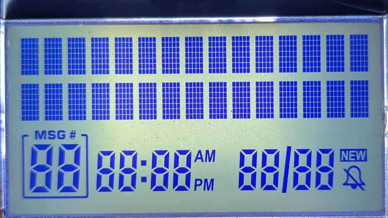
I have generated a printable lookup chart for the character set of an unknown LCD controller. This chip is embedded inside a black blob along the top edge of an LCD I salvaged from the base station of an AT&T CL84209 cordless phone system. The character set dictates what is rendered in two lines of 15-character alphanumeric text, each character is a dot matrix 5 pixels wide and 7 pixels tall. Below these two lines is a set of custom segmented LCD that can be controlled with 16 bytes, but there appear to be far fewer than 16*8 = 128 segments to control. A segment map will tell us which segments correspond to which bits.

I don’t have the datasheet for this chip, so I don’t know how it numbered its segments. I decided to mostly follow the precedence set by Sanyo LC75853 by numbering both bits and bytes in least-significant-first order. The difference for this map is that while LC75853 started counting from one, I’m going to start counting from zero.
My first attempt at mapping out these segments toggled them on/off alongside the character set data. When displaying characters starting with 0x00, I turned on all the segments whose number has zeroth bit set. For the character set starting with 0x10, I turned on all the segments with the next bit set, etc. In theory I could look at the on/off pattern as it cycled through 0x00 to 0x70 and determine its binary number. I also printed out the bit pattern to Arduino serial console, which looks like this:
0 1 10101010 10101010 10101010 10101010 10101010 10101010 10101010 10101010 10101010 10101010 10101010 10101010 10101010 10101010 10101010 10101010
1 10 11001100 11001100 11001100 11001100 11001100 11001100 11001100 11001100 11001100 11001100 11001100 11001100 11001100 11001100 11001100 11001100
2 100 11110000 11110000 11110000 11110000 11110000 11110000 11110000 11110000 11110000 11110000 11110000 11110000 11110000 11110000 11110000 11110000
3 1000 0 11111111 0 11111111 0 11111111 0 11111111 0 11111111 0 11111111 0 11111111 0 11111111
4 10000 0 0 11111111 11111111 0 0 11111111 11111111 0 0 11111111 11111111 0 0 11111111 11111111
5 100000 0 0 0 0 11111111 11111111 11111111 11111111 0 0 0 0 11111111 11111111 11111111 11111111
6 1000000 0 0 0 0 0 0 0 0 11111111 11111111 11111111 11111111 11111111 11111111 11111111 11111111
7 10000000 0 0 0 0 0 0 0 0 0 0 0 0 0 0 0 0
In theory this can work, in practice I quickly got tired flipping through images and decoding binary numbers by hand. That was a lot more work than having a quadrature encoder knob to interactively select segments to activate. I had avoided wiring in extra components out of laziness, but between manual binary decoding and soldering, I decided a bit of soldering was the easier path towards this segment map:
This map clearly showed this particular segment allocation used less than 5/8 of available segments. Starting from position zero, we would have five bits for five segments (0, 1, 2, 3, 4) then three bits that were unused. (5, 6, 7) Then five more segments (8, 9, 10, 11, 12) and three unused bits (13, 14, 15). This repeats until the final set of five (120, 121, 122, 123, 124) which were also unused.
I was surprised that segment 9 (“MSG#” title for message count) was a separate segment from 4, the rectangular border around message count. I had expected them to be a single segment.
I was also surprised and annoyed at segment 27, which lights up all three horizontal lines of the hour tens digit for the clock plus the lower left vertical segment. For a clock it made sense to restrict the tens digit to 1 or 2. But if so, why did they bother with segment 26 which isn’t useful for either of those digits? I had hoped maybe I could use it as a generic numeral display and not a clock, by leaving 65 and 66 (AM/PM) inactive. But segment 27 means I could only display 1, 2, 6, and 8. I have not yet thought of an interesting non-clock usage under those restrictions.
Obtaining a full segment map marks the end of investigating this base station LCD, I will now try to do the same for the handset LCD starting with its disassembly.
Source code for this investigation is publicly available on GitHub.

