Honda CD LCD Segment Map

I can talk to the LC75883 LCD driver chip on the faceplate of a Honda Accord CD/HVAC control panel, but I encountered problems using other peripherals. I don’t have the schematics for the circuit board and it would be a lot of work to generate one myself. At the moment I don’t have the motivation to undertake such a project. I have control of its LCD segments and I could generate a segment map for it:

Almost a quarter of the surface area on this LCD are allocated to CD icons 1 through 6, and many segments were consumed by the little circular graphic in the center. I guess that’s supposed to resemble a CD? We can control each pie slice to perform a rotating animation, but I was disappointed to learn the four dashes of each pie slice could not be controlled independently. So it is not possible to do a growing/shrinking circle animation, dashing my hopes of a polar coordinate VU meter. The clock up top is more or less as expected, but the four digits to the left and right of the circle are bizarre. Multiple different patterns that probably allows them to display certain letters in addition to numbers.

At least there weren’t too many segments that mislead us into think they were distinct segments. The most expected one was segment 9, which is actually both segments of the “1” and that makes sense for a clock that only needs to show 10, 11, and 12. Segment 60 includes both left and right brackets around the center, but I couldn’t think of many reasons why we’d want to control them separately anyway. The most bizarre is 134, which occupies 5 out of 7 segments of the right-most sub-sized digit. With it, that digit could only display 5, 6, 8, and 9. How is this useful? If I ever get a chance to play with the stock CD player of a 2007 Honda Accord, I want to see how this thing used to work. Right now, I ponder my next step.

CL84209 Handset LCD Segment Map

Now that I’m properly driving this salvaged LCD, using its own voltage boost converter, I’ll map out its custom segments. The two lines of 15-character text uses the same character set as the LCD used in the base station of this AT&T CL84209 cordless phone system, but one space off from each other. On the lower half of the screen, this handset LCD has a different set of segments than the base station LCD. Fortunately, as they both respond to the same control protocol, I could use the same ESP8266 Arduino program to interactively select individual segments and write down which segment respond to which bits.

Comparing with the base station LCD segment map, there are some differences with obvious causes. For example, a battery gauge makes sense for the battery-powered handset. The battery outline segment (12) was an extremely informative element when I analyzed the digital control traffic, because it had been blinking on/off to signal low supply voltage and seeing that bit toggling on and off helped me zero in on the segment control bits. And now that I’m thinking about it, perhaps a blinking outline explains why 64 (outline around count of messages) and 100 (the actual “MSG#” text) are two separate segments. This was a design decision that puzzled me when looking at the base station LCD, but now I understand it gives the option of keeping “MSG#” on while the border blinks.

This handset LCD has a few additional custom segments, but two fewer 7-segment numeric digits. However, the hour tens digit of its clock area is thankfully a fully controllable 7-segment display, versus the base station LCD where all three horizontal lines were the same segment drastically limiting the digits it could display.

Numbering-wise, I see the “use 5 bits then skip 3” pattern. For example: 8, 9, 10, 11, 12 were used, then 13, 14, and 15 were skipped. I assume this has something to do with the segment/common convenience of wiring but couldn’t guess more without the chart like I had for Sanyo LC75853. Like the base station LCD, this handset LCD also skipped a byte entirely. Except in this case, it skipped the first byte (the first used bit was bit 8) instead of the final byte.

Putting together this segment map concludes the software side of exploring this LCD, I will now resume physical/mechanical exploration by taking apart this display assembly.


Source code for this investigation is publicly available on GitHub.

CL84209 Base Station LCD Segment Map

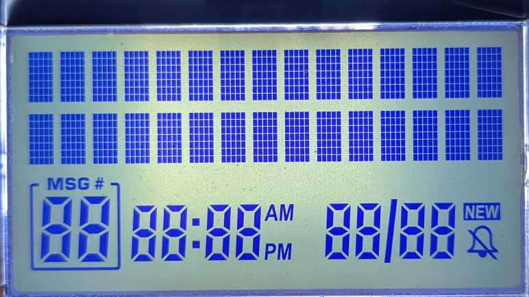
I have generated a printable lookup chart for the character set of an unknown LCD controller. This chip is embedded inside a black blob along the top edge of an LCD I salvaged from the base station of an AT&T CL84209 cordless phone system. The character set dictates what is rendered in two lines of 15-character alphanumeric text, each character is a dot matrix 5 pixels wide and 7 pixels tall. Below these two lines is a set of custom segmented LCD that can be controlled with 16 bytes, but there appear to be far fewer than 16*8 = 128 segments to control. A segment map will tell us which segments correspond to which bits.

I don’t have the datasheet for this chip, so I don’t know how it numbered its segments. I decided to mostly follow the precedence set by Sanyo LC75853 by numbering both bits and bytes in least-significant-first order. The difference for this map is that while LC75853 started counting from one, I’m going to start counting from zero.

My first attempt at mapping out these segments toggled them on/off alongside the character set data. When displaying characters starting with 0x00, I turned on all the segments whose number has zeroth bit set. For the character set starting with 0x10, I turned on all the segments with the next bit set, etc. In theory I could look at the on/off pattern as it cycled through 0x00 to 0x70 and determine its binary number. I also printed out the bit pattern to Arduino serial console, which looks like this:

0 1 10101010 10101010 10101010 10101010 10101010 10101010 10101010 10101010 10101010 10101010 10101010 10101010 10101010 10101010 10101010 10101010 
1 10 11001100 11001100 11001100 11001100 11001100 11001100 11001100 11001100 11001100 11001100 11001100 11001100 11001100 11001100 11001100 11001100 
2 100 11110000 11110000 11110000 11110000 11110000 11110000 11110000 11110000 11110000 11110000 11110000 11110000 11110000 11110000 11110000 11110000 
3 1000 0 11111111 0 11111111 0 11111111 0 11111111 0 11111111 0 11111111 0 11111111 0 11111111 
4 10000 0 0 11111111 11111111 0 0 11111111 11111111 0 0 11111111 11111111 0 0 11111111 11111111 
5 100000 0 0 0 0 11111111 11111111 11111111 11111111 0 0 0 0 11111111 11111111 11111111 11111111 
6 1000000 0 0 0 0 0 0 0 0 11111111 11111111 11111111 11111111 11111111 11111111 11111111 11111111 
7 10000000 0 0 0 0 0 0 0 0 0 0 0 0 0 0 0 0 

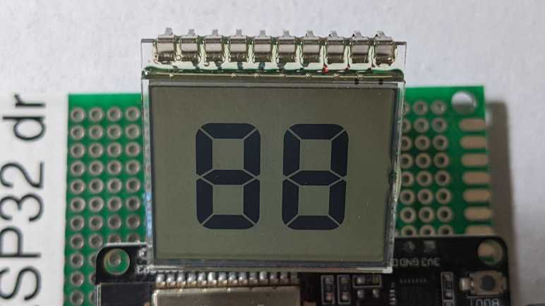
In theory this can work, in practice I quickly got tired flipping through images and decoding binary numbers by hand. That was a lot more work than having a quadrature encoder knob to interactively select segments to activate. I had avoided wiring in extra components out of laziness, but between manual binary decoding and soldering, I decided a bit of soldering was the easier path towards this segment map:

This map clearly showed this particular segment allocation used less than 5/8 of available segments. Starting from position zero, we would have five bits for five segments (0, 1, 2, 3, 4) then three bits that were unused. (5, 6, 7) Then five more segments (8, 9, 10, 11, 12) and three unused bits (13, 14, 15). This repeats until the final set of five (120, 121, 122, 123, 124) which were also unused.

I was surprised that segment 9 (“MSG#” title for message count) was a separate segment from 4, the rectangular border around message count. I had expected them to be a single segment.

I was also surprised and annoyed at segment 27, which lights up all three horizontal lines of the hour tens digit for the clock plus the lower left vertical segment. For a clock it made sense to restrict the tens digit to 1 or 2. But if so, why did they bother with segment 26 which isn’t useful for either of those digits? I had hoped maybe I could use it as a generic numeral display and not a clock, by leaving 65 and 66 (AM/PM) inactive. But segment 27 means I could only display 1, 2, 6, and 8. I have not yet thought of an interesting non-clock usage under those restrictions.

Obtaining a full segment map marks the end of investigating this base station LCD, I will now try to do the same for the handset LCD starting with its disassembly.


Source code for this investigation is publicly available on GitHub.

Segmented LCD on Tape Deck Faceplate (Toyota 86120-08010)

Thanks to well-labeled connectors and an online datasheet, I can write Arduino code to control faceplate LCD of the stock tape deck audio unit from a 1998 Toyota Camry LE. (86120-08010). However, knowledge of the digital wiring doesn’t tell me anything about the physical location and shape of each segment in the LCD. I will build a segment map with the help of a knob already on the faceplate. The Sanyo LC75853N chip could control up to 126 segments. I edited my Arduino program to turn on all of them, so I could take this picture to see where segments even existed.

It reflected the custom nature of a segmented LCD. Some of these digits would only ever display numbers, so they had the standard 7 segments for numeric display. Others have a secondary use to display letters for a few audio settings, and those digits had more than 7 segments. But they can’t display arbitrary letters, only exactly what was needed and no more.

With the full set of available segments in hand, I changed the program to turn on just one segment at a time interactively selected via the “Audio Mode” knob. Since each segment is a single bit, I could print out my control bits to Arduino serial monitor to see current active segment’s programmatic address.

I’m using the same numbering system as used in the datasheet, D1 to D126. From there, I generated this segment map:

LCD segment map for 86120-08010. Click to view full size.

When I first started my Arduino program, I saw nothing for the first few turns of the dial. I thought perhaps my program was faulty, but a few turns later I saw my first result for D13. From there on it was relatively straightforward, working from bottom-to-top and right-to-left. Some notes:

  • D24 is missing, a mysterious gap.
  • There were a few segments that I had thought were separate but were actually the same segment. For example, two visually distinct segments were actually just D54. This was disappointing, because it restricted the number of letters we could show. (Example: a good looking “M” would be possible, but a good looking “N” wouldn’t.)
  • Along the same lines, some numeric segments looked like separate segments purely for the sake of preserving the 7-segment aesthetic. The three segments D101, D102, and D105 together could display either “1” or “2” but visually looked like 6 segments instead of 3.
  • The leftmost large numeric digit puzzled me. It could only display 1, which is fine. But given that, why are the two segments D91 and D92 individually addressable? I can’t think of a reason why we’d want to display only the top or bottom half of a “1”.

Here is a table from the LC75853N datasheet mapping segment numbers to pins. I colored in the segments that were seen and a clear pattern emerged: This LCD allocation avoided using the first four pins (S1-S4) leaving the option of using them as general-purpose output wires. (P1-P4) At the end, stopping at D105 meant they didn’t have to wire up the final seven output pins. (The final two S41 and S42 would have had to been reallocated from key scan duty KS1 and KS2, if used.)

None of this explains why D24 is missing. The answer to this mystery must lie elsewhere.

Now that I know what is on this LCD available to display, maybe I can think of a creative way to reuse it. While I think that over, I’ll proceed to work through how to read input from this faceplate.


Source code for this investigation is publicly available on GitHub.

Segmented LCD From Taylor Food Thermometer

After figuring out the segmented LCD module salvaged from an electric blanket controller, I revisited the food thermometer LCD that foiled my first attempt at deciphering its multiplex encoding. This time I have a smaller solder tip to maneuver in limited space. I also have finer wires with softer insulation to reduce stress on these solder joints. And finally, instead of individual pins I will solder all of these wires to a perforated prototype board with pin headers, so that they all share physical stress together. The perforated board also had letters across the top, so I had convenient labels for each of the wires: A through W.

These changes solved the wiring continuity problem, but I hadn’t addressed the problem of applying pressure on the elastomeric “zebra strip” to keep it in contact with copper pads on the circuit board. Or at least, not elegantly.

“Not elegantly” meant there are two different types of tape involved, numerous spacers in various locations, and a small clamp all working together to keep that elastomeric strip in contact with the circuit board. If I am to reuse this LCD, I definitely need a better solution than this jury-rigged setup.

But it was good enough for me to obtain this mapping, scribbling things down as I went. In my earlier effort, I decided this screen didn’t use a typical segment/common pin split. I was wrong! Misled by poor electrical connections. This screen used 18 segments that ended up on my perforated prototype board as A through R. The five common pins ended up on S through W.

Once the segment and common pins were identified, I could wire up my test circuit to activate all segments on this LCD. And from this picture, I can translate my scribbled notes into a more legible segment map.

Some notes on this imperfect segment map:

  • There was crosstalk between pins C and D on my test setup, so they both activate if either is powered. Usually, one is blurrier than the other, but sometimes they look roughly equal and I had to guess which was which. So some of the C/D segments on this map may be reversed. (For example, C3 might actually be D3, and vice versa.)
  • I had intermittent connection on pin N. N0, specifically, was not seen (It was missing from the hand drawn map above) and was filled in, inferred, via a process of elimination.
  • The hundreds digit for the two temperatures can only show 1, 2, or 3. The three horizontal elements are all a single segment, and it is missing the segment to show 4. This makes sense for a food thermometer: while an oven can be set to be 400 degrees or higher, our food would be a charred hulk by the time it reaches that temperature so it’s not really relevant for a food thermometer.
  • The units for temperatures can be “C” or “F” and they only differ by one segment. All the remaining segments are fixed together along with a text label and the degree symbol. (B3 and Q3.)
  • R behaved strangely. It is associated with the “Timer” text in the upper right and the middle horizontal segment of “F” in the lower right. They seem to both illuminate regardless of which common pin is active, but that doesn’t make sense because there’s no reason for “Timer” text to be mutually exclusive with using Celsius units. Additional investigation is needed here but that requires individual segment control that I currently lack.

If I want to play with this LCD further, the first requirement is to get a better mounting system to send signal through that elastomeric strip. No tapes, spacers, or clamps. And in order to have individual control over segments, I’ll need either a dedicated LCD driver chip or a microcontroller with at least 18+5 = 23 GPIO pins. This is far beyond the number of pins available on an ESP32 so I’ll need to get up to speed on some other microcontroller if I want to tackle such a project.

For now, this LCD will not go back to the “I don’t know if I can use it” pile of salvaged electronics. It has been upgraded to the “I know I can use it and I’m waiting for a project idea” collection. I love making such an upgrade, and I want to see if I can do the same for a salvaged automotive tape deck faceplate.

Segmented LCD From Sunbeam PAC-215

I now have imperfect but working control of a 2-digit 7-segment LCD module salvaged from a Sunbeam PAC-215 electric blanket controller. I used an ESP32 for this initial run because I thought I needed voltage control over all ten pins. After a little bit of experimentation, I’ve found that I could probably get away with using 0V and 3.3V directly on each of the segment pins. For the common pins I need an additional option of the midway point 1.65V, but if it is true that an LCD uses very little current, perhaps I could supply that voltage with merely a voltage divider built from resistors? If true, I might be able to control this with something far simpler and less powerful than an ESP32. Perhaps an ATmega328 (Arduino)? Or a PIC16F18345, which has a DAC peripheral and already on hand. (If I’m going to buy a chip, I’ll take Joey Castillo’s suggestion and buy one with LCD control peripheral built in.) These are potential experiments for the future. For now, I want to wrap up work with this particular pair of salvaged LCDs which means leaving good notes for my future self.

I scribbled down this diagram when probing the pins. The pins were numbered before I knew what they did. Now that I know which are segment and which are common, I could label them differently.

I also moved to a zero-based counting system thinking it might be easier to match up to code. Color-coding the different common pins is an idea I picked up from Joey Castillo’s slides, but I wonder if that’s the best way to go. I can’t claim to be an expert on how to use color in a way that’s still accessible to the color blind, and coding common pin information in color risks losing data for scenarios like printing on a black-and-white laser printer.

Moving to letters for segments and numbers for common allows me to put them together as labels on each segment while reducing ambiguity. This is also friendlier to black-and-white printing, but it loses the visual delineation of color coding. Is this better? I don’t know as I see strengths in each. I couldn’t make up my mind on which to keep so I’ll keep both of these diagrams here as references for later.

With this successful milestone of working with LCD modules, I revisited a module that frustrated me earlier.