After borrowing a Raspberry Pi Pico W board to play with, I had many ideas I wanted to try out. The first test was Home Assistant support via ESPHome, and this was a success. In fact, I think getting ESPHome started on a Pico W is even easier than doing the same on their namesake Espressif boards.
A tremendously useful feature of ESPHome is the ability to perform updates over WiFi. This over-the-air (OTA) capability means every ESPHome-powered node in a Home Assistant network can be updated wherever they are around the house, no need to bring them back to a computer with a USB cable (or bring a laptop with USB cable out to them). However, this only works after ESPHome is already running on board, which means initial ESPHome setup on a microcontroller still require a USB connection to install a compiled binary file.
For ESP8266 and ESP32 board, this means connecting it directly to the computer running Home Assistant which can get complicated depending on how Home Assistant is set up and whether its ESPHome plug-in can access USB ports. Alternatively, it can be installed by an ESPHome web tool. Or we can install Espressif’s esptool flash utility on a computer. So this is a solvable problem.
But a Pico W has an even easier way: do it on any modern computer, no software installation required. Because when we hold down the “BOOTSEL” button upon powerup, the Pico W presents itself as a generic USB storage device, to which we can copy the compiled binary file (it has a *.uf2 extension) and the Pico W is off and running. Very nice!
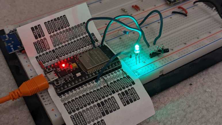
As is typical microcontroller practice, my “Hello World” is to connect a LED to my Pico W and toggle it on/off from Home Assistant. I saw an onboard LED, labeled GPIO25 on a pinout chart, and thought I would use that. When that didn’t work, I looked closer and realized I had mistakenly referenced the pinout chart for a Pico (not W) and Pico W’s onboard LED is actually connected to its WiFi chip instead of 25. Oops! It’s not clear to me where pin 25 was routed on a Pico W, so I switched gears: I connected an external LED with current-limiting resistor to pin 15. And since the board was already running ESPHome firmware, I could do an OTA update to use pin 15 instead.
I’ve got a set of inexpensive load cells hooked up to log signs whether I’m getting a good night’s sleep. It was an experiment that was both interesting to me and fits within the quite-significant limitations of these cheap little things. I’m going to leave that setup collecting data for a while, in the meantime I want to write down details on the software side before I forget.
I did not try to compensate for temperature or for system warmup, those two together could affect final weight output by as much as half a kilogram. But in the specific purpose of tracking changes on a minute-by-minute basis, those factors could be ignored.
This sensor and HX711 amplifier combination has a recurring issue sending occasional readings that do not reflect what’s actually happening. To minimize effect of these spurious data points, I have taken the following measures:
The reported weight value is the median weight out of the past minute and a half. Median value filter is more tolerant of spurious data of drastically different values.
Once I had everything set up, I noted the minimum measured value (empty bed) and the maximum expected value (bed with me in it) and discarded all values outside of that range as “Off Scale Low” and “Off Scale High”. That will throw out some spurious data but still leaves those within the expected range.
The reported delta value is not the difference between the maximum and minimum values seen within a time window. I track the second-largest and second-smallest values and report that delta instead. This way I can ignore spurious outliers, though it only works as long as spurious data doesn’t happen multiple times within a minute. Fortunately that’s been the case so far. If the problem gets worse I’ll have to devise something else.
And here’s the ESPHome YAML. If you want to copy/paste this code, feel free to do so. But make sure the values of hx711 “dout_pin” and “clk_pin” matches your hardware. The constants used to filter off-scale high/low will also need to be adjusted to fit your setup:
sensor:
  - platform: template
    name: "Delta"
    id: load_cell_delta
    accuracy_decimals: 0
    update_interval: never # updates only from code, no auto-updates
  - platform: template
    name: "Off Scale Low"
    id: load_cell_toolow
    accuracy_decimals: 0
    update_interval: never # updates only from code, no auto-updates
  - platform: template
    name: "Off Scale High"
    id: load_cell_toohigh
    accuracy_decimals: 0
    update_interval: never # updates only from code, no auto-updates
  - platform: hx711
    name: "Filtered"
    dout_pin: D2
    clk_pin: D1
    gain: 128
    update_interval: 0.5s
    filters:
      median:
        window_size: 180
        send_every: 120
    on_raw_value:
      then:
        lambda: |-
          static int load_window = 0;
          static float load_max = 0.0;
          static float load_second_max = 0.0;
          static float load_min = 0.0;
          static float load_second_min = 0.0;

          // Ignore spurious readings that imply negative weight
          if (x > -500000) // Constant experimentally determined for each setup
          {
            id(load_cell_toolow).publish_state(x);
            return;
          }
          // Ignore spurious readings that exceed expected maximum weight
          if (x < -1500000) // Constant experimentally determined for each setup
          {
            id(load_cell_toohigh).publish_state(x);
            return;
          }

          // Reached the end of our min/max window, publish observed delta
          if (load_window++ > 120)
          {
            load_window = 0;

            // Use second largest/smallest values, in case the absolute
            // max/min were outliers.
            id(load_cell_delta).publish_state(load_second_max-load_second_min);
          }

          if (load_window == 1)
          {
            // Starting a new min/max window
            load_max = x;
            load_second_max = x;
            load_min = x;
            load_second_min = x;
          }
          else
          {
            // Update observations in min/max window
            if (x > load_max)
            {
              load_second_max = load_max;
              load_max = x;
            }
            if (x < load_min)
            {
              load_second_min = load_min;
              load_min = x;
            }
          }
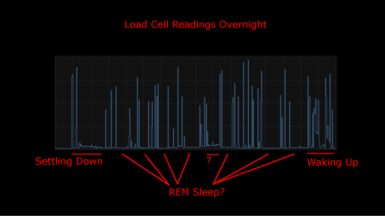
I took an inexpensive HX711-based load cell setup (the type that measures body weight in a bathroom scale) and installed them under my mattress. I wasn’t interested in measuring my weight while I sleep, I was interested in changes that indicate movement while sleeping. Ideally, I would see pauses in the data implying muscle inhibition associated rapid-eye movement (REM) sleep. I would take lack of movement as an indication of restful sleep. Logged to my Home Assistant database, here’s a plot of first night’s data:
This was a relatively restful night where I woke up refreshed. Looking at the plot, I can see when I got into bed and muscle activity gradually reducing as I fell asleep. There are multiple periods of nearly zero movement, implying a nice deep sleep in my cycle. As I started waking up in the morning, the load cell picked up more activity.
There was one unexplained set of data halfway through the night, where the movement activity is low but not as low as restful periods. The movement resembled my “settling down” period. I wonder if I woke up for some reason and had to fall back asleep? If so, I have no memory of this.
For comparison, here’s a graph of a different night’s data:
It was not a restful night of sleep. I have vague memories of waking up in the middle of the night, tossing and turning. I also woke up exhausted which corroborated with this plot of measured weight delta. It took longer before I fell asleep, there were far fewer periods of restful low movement, and I started to stir much earlier before I got out of bed.
I’ll keep the system running for a while, logging information from a time when I’m asleep and unconscious. But that’s about as far as I’m going to go. It would take more sleep science knowledge to analyze this data further and I’m not inclined to do so. Partially because this was a really cheap load cell + HX711 amplifier chip combo delivering unreliable data. Some of these “movements” may just be spurious data from the sensor. I wouldn’t read too much further into it, it’s just a fun project and not a serious health diagnosis tool. But here’s my ESPHome/HX711 code if anyone wants to play with it.
I didn’t expect a lot when I paid less than $10 for a set of load cells from Amazon, and indeed it has some pretty significant limitations. But that’s fine, every instrument has limitations and it’s a matter of making sure an application fit within them. Looking at the limitations of this sensor, I thought I had the perfect project fit: use them to gain some insight on my sleep quality.
Quality of sleep is important and there’s a lot of research behind it. For the home scientist, one of the easiest metrics to measure is the fraction of time we stay still in rapid-eye movement (REM) sleep. Problems disrupting sleep will cut into the amount of time we spend in REM sleep, depriving our brains of an important part of resting. Measuring actual eye movement is difficult, but (healthy) REM sleep also temporarily inhibits our muscles keeping our body still. This is an imperfect correlation: it is possible for muscle movements to happen while in REM sleep (should be small, though) and it is possible to stay still without being in REM sleep. Despite the imperfection, sleep movement is a good proxy.
There are many options to track sleep movement in the consumer medical technology field. Health wearables with accelerometers can do it, but it requires wearing the device while sleeping. Alternatives to wearing something include motion-detection cameras, but I’m not putting a camera in my bedroom. Using a set of cheap load cells seems like a good option, and logging data to my Home Assistant server at home is much better for personal privacy than a cloud-based solution.
I’ve already written my ESPHome YAML lambda tracking maximum/minimum values within a one-minute window. It was originally intended to quantify noise inherent in the system, but it works just as well to pick up changes on sensor readings. So, there will be no additional software work required.
On the hardware side, I have an IKEA bed frame with a series of slats holding up the mattress. I can put my sensors where the slat rests on the frame.
Load on all other slat-frame interface is not measured, which meant the absolute measured values will change depending on where my body is on the bed. Fortunately, the absolute value doesn’t matter because I’m only interested in changes minute-to-minute. Those changes over time are my sleep movement data. This also means I can ignore other problems with this instrument’s absolute values, like system warmup and daily temperature cycle sensitivity.
The bad news is the problem of spurious data will still impact this application. Such erroneous data will indicate movement when no actual movement has occurred. It means these measurements will understate the quality of my sleep by some unknown amount. (I slept better than the data indicated, but by how much?) However, given that the correlation between REM sleep and lack of motion is an imperfect one to begin with, perhaps this error is acceptable. The recorded data is pretty noisy but some patterns are visible.
I dusted off my inexpensive load cell system (read by a HX711 chip) and switched the associated microcontroller from an Arduino Nano to an ESP8266. That ESP8266 was then programmed using ESPHome to upload load cell readings to my Home Assistant server. I configured the ESP8266 to read every half second, but I’ve learned sending that much raw data directly to Home Assistant bogs down the system so that twice-a-second data is filtered to a summary report once a minute.
General Noise
One summary is generated by a small code snippet I wrote tracking the difference between maximum and minimum values seen within that minute. This gives me an idea of the natural level of noise in my particular configuration. If all other variables are unchanged, I saw a fluctuation of roughly 350 sensor counts, mostly within the range from 250 to 450.
The other summary is an average. Since I already had code tracking maximum and minimum, it wouldn’t have been hard to calculate my own average. But rather than adding those 3-5 lines of code, I used ESPHome’s built-in sliding window moving average filter because it was already there. Keeping the system running for a little over 24 hours, here’s the graph it generated:
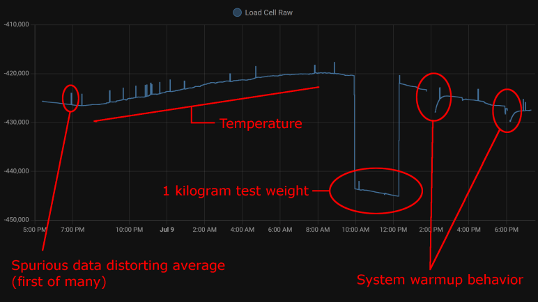
Spurious Data
The little spikes visible in this graph are caused by the occasional data that does not reflect reality. I saw this in my earlier experiments with the HX711 talking to Node-RED, but that only ran for a few minutes at a time. I had hoped that, by graphing its behavior over a day, I could observe some pattern.
There was no frequency-based pattern I could detect: they can happen mere minutes apart, and sometimes I can go for hours without one.
I only have a single day, which is not enough data to say if there’s a time-of-day pattern.
Visible spikes in the graph were caused by nonsensical values indicating less weight than when the load cell is completely unloaded: negative weight, so to speak. The raw sensor count is usually in the few thousands range when unloaded is approximately -420,000, a big enough difference to visibly throw off the average over 120 readings.
Even though “negative weight” is the most visible in this graph, there are also unexplained brief flashes of data in the positive weight domain, they just don’t throw off the average value as visibly on this plot.
Temperature Sensitivity
One behavior I never noticed during my short duration Node-RED experiments were the relation between sensor counts and temperature. With a full day’s worth of data plotted, the correlation is clearly visible. From around 7PM to 8AM the next day, temperature dropped from 28.2°C to 21.6°C. (Tracked elsewhere in my Home Assistant network, not on this graph.) During this 6.6°C drop, average sensor count rose from around -426,500 to -420,000. This rounds to approximately 1000 sensor counts per degree Celsius.
Kilogram Test
But what do those sensor counts correspond to? I used my kitchen scale to measure as I poured water into a jar, stopping when they weighed one kilogram together. I placed that on my test setup for two hours. This dropped sensor counts from around -420,000 to -443,000 (plus temperature-induced variation). Using 23,000 sensor counts per kilogram, I can tentatively guess the random noise of ~300 sensor counts correspond to roughly thirteen grams. This is consistent with my earlier observation I need roughly fifteen grams of weight change before it is barely distinguishable from noise.
By the same metric, temperature change for a single degree Celsius changes the reading by roughly 43 grams. Over the course of a day that varies by 6.6 degrees Celsius, that would change weight reading by roughly 280 grams.
System Warmup
I brainstormed on possible reasons for spurious data and thought perhaps they were caused by the JST-XH connectors I used. A small intermittent connection might not be noticed in most of my projects, but load cells work by slight changes in resistance and the HX711 amplifies those changes. Small flaws in a connector that would go unnoticed elsewhere would drastically change behavior here, so I unsoldered the connector and soldered all wires directly to the HX711 board.
That experiment was a bust, direct soldering did not eliminate spurious data. I still don’t know where that’s coming from. But I came out of it with an additional observation: When I disconnect the system for a while to work on it, then turn it back on, there’s a warmup curve visible on the plot. This graph had two such work sessions, and I see a curve of roughly 3000 sensor counts. That’s roughly 130 grams.
Conclusion
Based on these observations, I conclude this specific load cell setup is only dependable down to about half a kilogram before we have to worry about compensating for factors system warmup or ambient temperature. This is consistent with the primary use of these devices: inexpensive bathroom scales for measuring human body weight.
We also need to account for spurious data in some way, for example take multiple readings and average them, possibly ignoring readings that are wildly inconsistent with the rest.
And even if we somehow managed to compensate for environment variables, it’s not possible to reliably measure any changes less than ~20 grams because of fundamental noise in this system.
This isn’t bad for a $10 kit, but its limitations does constrain usefulness. After a bit of thought, I think I have a good project idea to fit this sensor.
A few years ago, I bought a cheap set of load cells to play with. The kind that performs weight measurement in an inexpensive bathroom scale. I got them up and running with the bundled HX711 board, sending data to Node-RED. Using this infrastructure, I performed a silly little (but interesting!) experiment measuring squishing behavior of packing material. I then got distracted with other Node-RED explorations and haven’t done anything with the HX711 load cell setup since. Now I’m going to dust it off (quite literally) and play with it again. This time, instead of Node-RED, I’ll be using the ESPHome + Home Assistant infrastructure.
There are multiple reasons for this switch. After a few experiments with Node-RED, I haven’t found it to be a good fit for the way I think. I like the promise of flow-based programming, and I like Node-RED’s implementation of the idea, but I have yet to find enough of an advantage to justify changing over. Node-RED promised to make prototyping fast, but I found something that got my prototypes up and running even quicker: ESPHome and Home Assistant. In my experiments to date, ESPHome’s YAML-based configuration lets me get simple straightforward components up and running even more quickly than I ever managed under Node-RED. And when I need to venture beyond the simple defaults, I can embed small fragments of C code to do just the special thing I need. This comes to me more naturally than using Node-RED’s counterpart function node with a snippet of JavaScript. It’s also very quick to put together simple UI using Home Assistant, though admittedly with far less control over layout than Node-RED’s dashboard.
But the primary motivation this time around is that I already had an instance of Home Assistant running, so I don’t need to set up logging infrastructure for longer-duration projects. Node-RED is perfectly capable of working with a database, of course, but I’d have to set something up. Home Assistant already has one built-in. By default, it stores data only locally, and only for ten days, making it much more privacy-friendly than internet-based solutions with wildly varying levels of respect for privacy.
Hardware changeover was pretty simple. The HX711 board needed four wires: power, ground, data, and clock. I unsoldered the Arduino Nano I previously installed and replaced it with an ESP8266. It will need to run ESPHome’s HX711 integration, which under the hood used the same PlatformIO library I had used earlier for the Arduino Nano. A few lines of YAML later, load cell data started streaming to my Home Assistant server for me to examine.
I wanted to use my fan strobe LED as a learning project to work with ESP32 hardware timers, but my original idea required modifying timer configuration from inside a timer alarm ISR. I have learned that is not allowed, and I have the crash stacks to prove it. The ESP32 Arduino Core timer API is geared towards timer alarm interrupts firing at regular intervals to run the same code repeatedly, so I should change my code structure to match.
Since the tachometer signal timing, strobe delay, and strobe duration could all change at runtime, I couldn’t use any of those factors as my hardware timer interval. Switching to a regular timing interval meant I would have to poll current status to determine what to do about state of LED illumination.
For the first draft, I kept a counter of how many times my ISR has executed. This variable is only updated by the ISR. Based on this counter value, each tachometer ISR calculates the time for LED to be turned on and back off in terms of timer ISR counter. Timer ISR compares those values to turn the LED on, then back off. When a particular pulse is complete, the timer ISR resets all counters to zero and waits for the next tachometer pulse to occur.
I tried a timer ISR duration of polling once every 20 microseconds. This meant a worst-case scenario of LED pulse starting as much as 20 microseconds later than specified, and a pulse duration as much as 20 microseconds longer than specified. When the ideal duration is around 200-250 microseconds, this is nearly 10% variation and resulted in visible flickering. I then tried 10 microseconds, and the flickering became less bothersome. On an ESP32 running at 240MHz, it meant I demand my ISR run once every 2400 clock cycles. I’m worried this is too demanding, but I don’t have a better idea at the moment. At least it hasn’t crashed my ESP32 after several minutes of running.
This new mechanism also allowed me to increase my LED strobe delay beyond a millisecond, but I noticed an irregular wobbling for longer delays. Those strobes of light are not happening at my calculated location. They vary by only a few degrees but very definitely noticeable. Is this a sign that my ISR is too demanding? For a multi-millisecond LED strobe delay, a 10-microsecond timer ISR would execute hundreds of times. If there’s a tiny but unpredictable amount of delay on each, they might add up to cause a visible wobble. Perhaps I should use a different counter with better consistency.
Custom component code with timer counter:
#include "esphome.h"
#include "esp_system.h"

volatile int evenOdd;
volatile int strobeDuration;
volatile int strobeDelay;
volatile int timerCount;
volatile int timerLEDOn;
volatile int timerLEDOff;

const int gpio_led = 23;
const int gpio_tach = 19;

hw_timer_t* pulse_timer = NULL;

IRAM_ATTR void timerCountersReset() {
  timerCount = 0;
  timerLEDOn = 0;
  timerLEDOff = 0;
}

IRAM_ATTR void pulse_timer_handler() {
  if (timerCount >= timerLEDOn) {
    digitalWrite(gpio_led, HIGH);
  }

  if (timerCount >= timerLEDOff) {
    digitalWrite(gpio_led, LOW);
    timerCountersReset();
  } else {
    timerCount++;
  }
}

IRAM_ATTR void tach_pulse_handler() {
  if (0 == evenOdd) {
    evenOdd = 1;
  } else {
    if (timerLEDOn == 0 && strobeDuration > 0) {
      // Calculate time for turning LED on and off
      timerLEDOn = timerCount + strobeDelay;
      timerLEDOff = timerLEDOn + strobeDuration;
    }
    evenOdd = 0;
  }
}

class FanStrobeLEDSetupComponent : public Component {
  public:
    void setup() override {
      // Initialize variables
      strobeDelay = 10;
      strobeDuration = 20;
      timerCountersReset();

      // LED power transistor starts OFF, which is LOW
      pinMode(gpio_led, OUTPUT);
      digitalWrite(gpio_led, LOW);

      // Attach interrupt to tachometer wire
      pinMode(gpio_tach, INPUT_PULLUP);
      evenOdd = 0;
      attachInterrupt(digitalPinToInterrupt(gpio_tach), tach_pulse_handler, RISING);

      // Configure hardware timer
      pulse_timer = timerBegin(0, 80, true);
      timerAttachInterrupt(pulse_timer, &pulse_timer_handler, true);
      timerAlarmWrite(pulse_timer, 10, true /* == autoreload */);
      timerAlarmEnable(pulse_timer);
    }
};

class FanStrobeLEDEvenOddToggleComponent: public Component, public Switch {
  public:
    void write_state(bool state) override {
      evenOdd = !evenOdd;
      publish_state(state);
    }
};

class FanStrobeLEDDelayComponent: public Component, public FloatOutput {
  public:
    void write_state(float state) override {
      strobeDelay = 1100*state;
    }
};

class FanStrobeLEDDurationComponent: public Component, public FloatOutput {
  public:
    void write_state(float state) override {
      strobeDuration = 100*state;
    }
};
Conceptually I knew using delayMicroseconds() inside an interrupt service routine (ISR) was a bad idea. But I tried it anyway on an ESP32 and now I have a crash stack to prove it was indeed a bad idea. A solid reason to switch over to using hardware timers. My fan strobe LED project has two needs: the first delay is between tachometer wire signal and turning LED on (this delay may be zero) followed by a second delay before turning LED back off. Duration of both of these delays vary in order to produce desired visual effects. Translating this concept directly into timers results in this pseudocode:
Interrupt handler triggered by tachometer signal. Starts timer that calls step 2 when first it ends.
Interrupt handler triggered by expiration of first delay. Turn on LED and start timer that calls step 3 when it ends.
Interrupt handler triggered by expiration of second delay, turn off LED.
Unfortunately, that direct translation doesn’t work. At least not with ESP32 Arduino Core Timer APIs. The timer alarm callback (“call step 2” and “call step 3” above) is specified at the time an alarm timer is configured, and not something I can change in between steps 2 and 3 above. Furthermore, I had no luck changing the timer duration in between calls, either. Either the change has no effect (duration doesn’t change) or the timer alarm interrupt stops triggering entirely. The only way I got something resembling my initial pseudocode is to tear down and rebuild a timer on every call to step 1, then do it again on step 2, and repeat.
That code felt wrong, and it didn’t take long for me to see concrete evidence it was wrong. I could adjust my delay parameters a few times, but within 2-3 minutes of running this sketch my ESP32 would crash with the following stack:
WARNING Found stack trace! Trying to decode it
WARNING Decoded 0x40088dcc: invoke_abort at /home/runner/work/esp32-arduino-lib-builder/esp32-arduino-lib-builder/esp-idf/components/esp32/panic.c:715
WARNING Decoded 0x40089049: abort at /home/runner/work/esp32-arduino-lib-builder/esp32-arduino-lib-builder/esp-idf/components/esp32/panic.c:715
WARNING Decoded 0x40089dbf: xQueueGenericReceive at /home/runner/work/esp32-arduino-lib-builder/esp32-arduino-lib-builder/esp-idf/components/freertos/queue.c:2038
WARNING Decoded 0x400f1001: removeApbChangeCallback at /data/cache/platformio/packages/framework-arduinoespressif32/cores/esp32/esp32-hal-cpu.c:224
WARNING Decoded 0x400817f9: timerEnd at /data/cache/platformio/packages/framework-arduinoespressif32/cores/esp32/esp32-hal-timer.c:174
WARNING Decoded 0x40081095: pulse_off_handler() at /config/esphome/.esphome/build/fan-strobe-led/src/esphome/core/gpio.h:62
WARNING Decoded 0x400814c9: __timerISR at /data/cache/platformio/packages/framework-arduinoespressif32/cores/esp32/esp32-hal-timer.c:174
WARNING Decoded 0x400874cd: _xt_lowint1 at /home/runner/work/esp32-arduino-lib-builder/esp32-arduino-lib-builder/esp-idf/components/freertos/xtensa_vectors.S:1154
WARNING Decoded 0x4008568d: esp_dport_access_int_abort at /home/runner/work/esp32-arduino-lib-builder/esp32-arduino-lib-builder/esp-idf/components/esp32/dport_access.c:216
WARNING Decoded 0x40087e63: spi_flash_enable_interrupts_caches_and_other_cpu at /home/runner/work/esp32-arduino-lib-builder/esp32-arduino-lib-builder/esp-idf/components/spi_flash/cache_utils.c:203
WARNING Decoded 0x4008857a: spi_flash_guard_end at /home/runner/work/esp32-arduino-lib-builder/esp32-arduino-lib-builder/esp-idf/components/spi_flash/flash_ops.c:172
 (inlined by) spi_flash_read at /home/runner/work/esp32-arduino-lib-builder/esp32-arduino-lib-builder/esp-idf/components/spi_flash/flash_ops.c:664
WARNING Decoded 0x401659c9: nvs::nvs_flash_read(unsigned int, void*, unsigned int) at /home/runner/work/esp32-arduino-lib-builder/esp32-arduino-lib-builder/esp-idf/components/nvs_flash/src/nvs_ops.cpp:76
WARNING Decoded 0x40164289: nvs::Page::readEntry(unsigned int, nvs::Item&) const at /home/runner/work/esp32-arduino-lib-builder/esp32-arduino-lib-builder/esp-idf/components/nvs_flash/src/nvs_page.cpp:871
WARNING Decoded 0x401642fd: nvs::Page::eraseEntryAndSpan(unsigned int) at /home/runner/work/esp32-arduino-lib-builder/esp32-arduino-lib-builder/esp-idf/components/nvs_flash/src/nvs_page.cpp:871
WARNING Decoded 0x40164979: nvs::Page::eraseItem(unsigned char, nvs::ItemType, char const*, unsigned char, nvs::VerOffset) at /home/runner/work/esp32-arduino-lib-builder/esp32-arduino-lib-builder/esp-idf/components/nvs_flash/src/nvs_page.cpp:871
WARNING Decoded 0x4016337a: nvs::Storage::eraseMultiPageBlob(unsigned char, char const*, nvs::VerOffset) at /home/runner/work/esp32-arduino-lib-builder/esp32-arduino-lib-builder/esp-idf/components/nvs_flash/src/nvs_storage.cpp:579
WARNING Decoded 0x40163751: nvs::Storage::writeItem(unsigned char, nvs::ItemType, char const*, void const*, unsigned int) at /home/runner/work/esp32-arduino-lib-builder/esp32-arduino-lib-builder/esp-idf/components/nvs_flash/src/nvs_storage.cpp:579
WARNING Decoded 0x40162b3b: nvs_set_blob at /home/runner/work/esp32-arduino-lib-builder/esp32-arduino-lib-builder/esp-idf/components/nvs_flash/src/nvs_api.cpp:547
WARNING Decoded 0x400d8407: esphome::esp32::ESP32Preferences::sync() at /config/esphome/.esphome/build/fan-strobe-led/src/esphome/components/esp32/preferences.cpp:124
WARNING Decoded 0x400e35dd: esphome::preferences::IntervalSyncer::on_shutdown() at /config/esphome/.esphome/build/fan-strobe-led/src/esphome/core/gpio.h:62
WARNING Decoded 0x400e3665: std::_Function_handler<void (), esphome::preferences::IntervalSyncer::setup()::{lambda()#1}>::_M_invoke(std::_Any_data const&) at /config/esphome/.esphome/build/fan-strobe-led/src/esphome/core/gpio.h:62
WARNING Decoded 0x400e34e6: std::function<void ()>::operator()() const at /data/cache/platformio/packages/toolchain-xtensa32/xtensa-esp32-elf/include/c++/5.2.0/functional:1710
 (inlined by) esphome::Scheduler::call() at /config/esphome/.esphome/build/fan-strobe-led/src/esphome/core/scheduler.cpp:204
WARNING Decoded 0x400e1319: esphome::Application::loop() at /config/esphome/.esphome/build/fan-strobe-led/src/esphome/core/application.cpp:69
WARNING Decoded 0x400e391e: loop() at /config/esphome/.esphome/build/fan-strobe-led/src/esphome/core/gpio.h:62
WARNING Decoded 0x400f0e29: loopTask(void*) at /data/cache/platformio/packages/framework-arduinoespressif32/cores/esp32/main.cpp:23
WARNING Decoded 0x4008a05a: vPortTaskWrapper at /home/runner/work/esp32-arduino-lib-builder/esp32-arduino-lib-builder/esp-idf/components/freertos/port.c:355 (discriminator 1)
I’m not sure what removeApbChangeCallback() meant. I found the code, but there were no code comments explaining what “Apb” is. A general web search found one potential explanation of “Advanced Peripheral Bus“. Whatever it is, it was called as part of a FreeRTOS queue receive. This was a surprise. I know FreeRTOS queues can be used from inside an ISR to schedule work to be performed outside an ISR, but that would be an ISR-safe queue send, not a receive. Hitting a receive path inside an ISR feels wrong.
Looking further down the call stack, I see NVS (nonvolatile storage) calls like I saw when I failed to use delayMicroseconds() on the stack. Why are storage APIs being called? I didn’t look into it earlier, hoping I could avoid the problem by moving to timers, but it’s clear I need to better understand what’s going on. Poking around in ESPHome code, I believe this is trying to save state of my parameters so it could be restored in case of system reset or shutdown. If so, I should be able to deactivate such behavior by setting restore_mode parameter to ALWAYS_OFF.
WARNING Found stack trace! Trying to decode it
WARNING Decoded 0x400f0ea8: initApbChangeCallback at /data/cache/platformio/packages/framework-arduinoespressif32/cores/esp32/esp32-hal-cpu.c:224
WARNING Decoded 0x400817e2: timerBegin at /data/cache/platformio/packages/framework-arduinoespressif32/cores/esp32/esp32-hal-timer.c:174
WARNING Decoded 0x4008110c: tach_pulse_handler() at /config/esphome/.esphome/build/fan-strobe-led/src/esphome/core/gpio.h:62
WARNING Decoded 0x40081185: __onPinInterrupt at /data/cache/platformio/packages/framework-arduinoespressif32/cores/esp32/esp32-hal-gpio.c:220
WARNING Decoded 0x400874dd: _xt_lowint1 at /home/runner/work/esp32-arduino-lib-builder/esp32-arduino-lib-builder/esp-idf/components/freertos/xtensa_vectors.S:1154
WARNING Decoded 0x40087c65: spi_flash_op_block_func at /home/runner/work/esp32-arduino-lib-builder/esp32-arduino-lib-builder/esp-idf/components/spi_flash/cache_utils.c:203
WARNING Decoded 0x40084f17: ipc_task at /home/runner/work/esp32-arduino-lib-builder/esp32-arduino-lib-builder/esp-idf/components/esp32/ipc.c:62
WARNING Decoded 0x4008a06a: vPortTaskWrapper at /home/runner/work/esp32-arduino-lib-builder/esp32-arduino-lib-builder/esp-idf/components/freertos/port.c:355 (discriminator 1)
The good news is that did indeed stop writes to nonvolatile storage. The bad news is that did not avoid crashing my ESP32. It’s still crashing on an Apb change callback, though this time without any NVS calls on the stack. (There’s still one line of spi_flash_op_block_func, though.) What’s going on? I decided to look deeper. Reading documentation for hardware timers in ESP-IDF (one layer below ESP32 Arduino Core) I saw the explanation: “It [ESP32 timer ISR callback] cannot call other timer APIs.” Aha! My timer ISR is not allowed to adjust and kick off another timer. This makes my initial pseudocode impossible to implement, and I have to devise a different approach.
My fan strobe LED project has a flaw where I used a time delay inside an interrupt service routine (ISR), a bad idea. Because that blocks other housekeeping task from occurring, which leads to other hard-to-diagnose problems. I didn’t know of a good way to resolve that problem with the ESP8266 microcontroller on board the Wemos D1 Mini module I had used, but I thought the more powerful ESP32 might do the job. Fortunately, I found an ESP32 dev board electrically compatible with the Wemos D1 Mini. Hardware-wise, I just had to solder a compatibility subset of 16 out of 40 pins to make a drop-in upgrade.
The software side needed more work, but thanks to ESPHome and the Arduino framework it is built upon, most of the changes are minor. Aside from updating GPIO pin numbers in ESPHome YAML and the custom component written in Arduino C, I switched fan control from ESP8266 software PWM to ESP32’s LEDC hardware PWM peripheral.
That leaves the star of the show: the ISR that turns the LED on and off triggered by fan tachometer signal. For this initial migration, I kept all the code as-is, including those problematic calls to delayMicroseconds(). Even though I intend to replace that code, I wanted to run it as-is at first to see any problems firsthand. I had thought that perhaps I would have more leeway for my ISR abuse with dual cores, because there’d a second core available to do work while I hoarded one.
Bad news: it did not. If anything, it appears that ESP32 is even more sensitive to my abuse. Or possibly I notice it more because the ESP32 had better crash information. It’s possible my ESP8266 sketch frequently crashed the controller and rebooted without my ever noticing something went wrong. With the ESP32, I get a lot more information with fully decoded stack trace, which takes nonzero time to generate and lets me notice the crashes. I love the fact that ESPHome incorporated all of this debugging infrastructure! It’s actually less effort for me to get a decoded crash stack via ESPHome than from within Arduino IDE. Sure, I had to connect a USB cable to see crash stack over serial, losing the wireless advantage of ESPHome, but that’s no worse than using Arduino IDE.
Judging by the crashing stack trace, my call to delayMicroseconds() was translated to esphome::delay_microseconds_safe(). And the fact it crashed told me that… well, it isn’t as safe as the author intended. Further down on the call stack, I see calls to ESP32 NVS subsystem, something I have learned was an ESP32 feature absent from the ESP8266. At first glance it implies delay_microseconds_safe() is not safe when called in the middle of a NVS write operation. No matter, the objective of this exercise is to get away from using delayMicroseconds() at all, so I should start working on that.
WARNING Found stack trace! Trying to decode it
WARNING Decoded 0x400e2cac: esphome::delay_microseconds_safe(unsigned int) at /data/cache/platformio/packages/toolchain-xtensa32/xtensa-esp32-elf/include/c++/5.2.0/bits/basic_string.h:195
WARNING Decoded 0x400810a0: pulse_timer_handler() at /config/esphome/.esphome/build/fan-strobe-led/src/esphome/core/gpio.h:62
WARNING Decoded 0x4008147d: __timerISR at /data/cache/platformio/packages/framework-arduinoespressif32/cores/esp32/esp32-hal-timer.c:174
WARNING Decoded 0x40087459: _xt_lowint1 at /home/runner/work/esp32-arduino-lib-builder/esp32-arduino-lib-builder/esp-idf/components/freertos/xtensa_vectors.S:1154
WARNING Decoded 0x4008f127: esp_rom_spiflash_read_status at /home/runner/work/esp32-arduino-lib-builder/esp32-arduino-lib-builder/esp-idf/components/spi_flash/spi_flash_rom_patch.c:662
WARNING Decoded 0x4008f162: esp_rom_spiflash_wait_idle at /home/runner/work/esp32-arduino-lib-builder/esp32-arduino-lib-builder/esp-idf/components/spi_flash/spi_flash_rom_patch.c:662
WARNING Decoded 0x4008f499: esp_rom_spiflash_program_page_internal at /home/runner/work/esp32-arduino-lib-builder/esp32-arduino-lib-builder/esp-idf/components/spi_flash/spi_flash_rom_patch.c:662
WARNING Decoded 0x4008f6c9: esp_rom_spiflash_write at /home/runner/work/esp32-arduino-lib-builder/esp32-arduino-lib-builder/esp-idf/components/spi_flash/spi_flash_rom_patch.c:662
WARNING Decoded 0x40087ec1: spi_flash_write_inner at /home/runner/work/esp32-arduino-lib-builder/esp32-arduino-lib-builder/esp-idf/components/spi_flash/flash_ops.c:155
WARNING Decoded 0x40088151: spi_flash_write at /home/runner/work/esp32-arduino-lib-builder/esp32-arduino-lib-builder/esp-idf/components/spi_flash/flash_ops.c:416
WARNING Decoded 0x40165a35: nvs::nvs_flash_write(unsigned int, void const*, unsigned int) at /home/runner/work/esp32-arduino-lib-builder/esp32-arduino-lib-builder/esp-idf/components/nvs_flash/src/nvs_ops.cpp:72
WARNING Decoded 0x40163e8e: nvs::Page::writeEntry(nvs::Item const&) at /home/runner/work/esp32-arduino-lib-builder/esp32-arduino-lib-builder/esp-idf/components/nvs_flash/src/nvs_page.cpp:871
WARNING Decoded 0x401641f9: nvs::Page::writeItem(unsigned char, nvs::ItemType, char const*, void const*, unsigned int, unsigned char) at /home/runner/work/esp32-arduino-lib-builder/esp32-arduino-lib-builder/esp-idf/components/nvs_flash/src/nvs_page.cpp:871
WARNING Decoded 0x40163220: nvs::Storage::writeMultiPageBlob(unsigned char, char const*, void const*, unsigned int, nvs::VerOffset) at /home/runner/work/esp32-arduino-lib-builder/esp32-arduino-lib-builder/esp-idf/components/nvs_flash/src/nvs_storage.cpp:579
WARNING Decoded 0x401637b6: nvs::Storage::writeItem(unsigned char, nvs::ItemType, char const*, void const*, unsigned int) at /home/runner/work/esp32-arduino-lib-builder/esp32-arduino-lib-builder/esp-idf/components/nvs_flash/src/nvs_storage.cpp:579
WARNING Decoded 0x40162bbb: nvs_set_blob at /home/runner/work/esp32-arduino-lib-builder/esp32-arduino-lib-builder/esp-idf/components/nvs_flash/src/nvs_api.cpp:547
WARNING Decoded 0x400d8413: esphome::esp32::ESP32Preferences::sync() at /config/esphome/.esphome/build/fan-strobe-led/src/esphome/components/esp32/preferences.cpp:124
WARNING Decoded 0x400e3621: esphome::preferences::IntervalSyncer::on_shutdown() at /config/esphome/.esphome/build/fan-strobe-led/src/esphome/core/gpio.h:62
WARNING Decoded 0x400e36a9: std::_Function_handler<void (), esphome::preferences::IntervalSyncer::setup()::{lambda()#1}>::_M_invoke(std::_Any_data const&) at /config/esphome/.esphome/build/fan-strobe-led/src/esphome/core/gpio.h:62
WARNING Decoded 0x400e352a: std::function<void ()>::operator()() const at /data/cache/platformio/packages/toolchain-xtensa32/xtensa-esp32-elf/include/c++/5.2.0/functional:1710
 (inlined by) esphome::Scheduler::call() at /config/esphome/.esphome/build/fan-strobe-led/src/esphome/core/scheduler.cpp:204
WARNING Decoded 0x400e1325: esphome::Application::loop() at /config/esphome/.esphome/build/fan-strobe-led/src/esphome/core/application.cpp:69
WARNING Decoded 0x400e399e: loop() at /config/esphome/.esphome/build/fan-strobe-led/src/esphome/core/gpio.h:62
WARNING Decoded 0x400f0ea9: loopTask(void*) at /data/cache/platformio/packages/framework-arduinoespressif32/cores/esp32/main.cpp:23
WARNING Decoded 0x40089ff6: vPortTaskWrapper at /home/runner/work/esp32-arduino-lib-builder/esp32-arduino-lib-builder/esp-idf/components/freertos/port.c:355 (discriminator 1)
After proving my fan blade LED strobe idea worked with a minimalist Arduino sketch, I ported that code over as an ESPHome custom component. I thought it would be good practice for writing ESPHome custom components and gain Home Assistant benefit of adding adjustments in software. For me it was easier to create an analog control with a few lines of YAML and C, than it would be to wire up a potentiometer. (I recognize it may be the reverse for people more comfortable with hardware than software.)
The first adjustment “Fan Speed Control” actually did not require custom component at all: making the fan speed adjustable utilized the built-in fan speed component. In my minimalist sketch the fan is always running at full speed, now I can adjust fan speed and verify that the strobe logic indeed stays in sync with the fan speed. Meaning the strobe keeps these fan blades visually frozen in the same place regardless of their rotational speed.
The first custom output component adjustment “Strobe Duration” changes the duration of LED strobe pulse, from zero to 1000 microseconds. For this LED array, I found values under 100 to be too dim to be useful. The dimmest usable value is around 100, and things seem to work well up to 300. I start detecting motion blur above 300, and things are pretty smeared out above 600.
The next addition is a toggle switch “Strobe Tachometer Toggle”. Because the tachometer signal pulses twice per revolution, I ignore every other pulse. But that means a 50% chance the code will choose to trigger on the wrong pulse, resulting in a visually upside-down image. When this happens, this toggle allows us to flip to trigger on the opposing pulse, flipping the frozen visual right-side up.
The final custom component adjustment “Strobe Delay” adds a delay between triggered by tachometer wire and illumination of LED strobe. This changes the point at which the fan is visually frozen by the strobe light. Dynamically adjusting this value makes it look like the fan blade is slowly rotating position even though it is actually rotating at ~1200RPM. I think it is a fun effect, but to fully take advantage of that effect I will need longer delays, which means finding how I could move that work outside of my interrupt service routine. Inside the ISR I should set up a hardware timer for this delay and turn on LED when timer expires. I can then use the same mechanism to set a timer for LED duration and turn off LED when that timer expires.
Unfortunately, there are only two hardware timers on an ESP8266, and they are both spoken for. One runs WiFi, the other runs Arduino core for things like millis(). To explore this idea further, I will need to move up to an ESP32 which has additional hardware timers exposed to its Arduino core. And if I choose to explore that path, I don’t even need to redo my circuit board: there exists a (mostly) drop-in ESP32 upgrade for anything that runs a Wemos D1 Mini.
If a delay is added between tachometer pulse and LED illumination, the visual shifts to a different location. Varying this delay over time can "rotate" the image at any speed independent of actual fan rotation speed, even backwards! pic.twitter.com/fqbAvhgFJZ
I have a revised bedside fan (now with integrated LED illumination) up and running, and now it needs a temperature sensor. The goal is so I could automate turning off the fan once things cool down. My previous attempt used a TMP36 sensor that reported results as an analog voltage level. The results made me feel it was not a good fit with ESP8266 ADC peripheral. I don’t blame Espressif, it’s just a matter of different ADC designed for different usage requirements.
As an alternative to TMP36, I wanted to try a sensor that has its own integrated analog circuitry designed for the purpose and reported measurements via a digital communication protocol. Between what I could find in how-to guides and listed by vendors competing on price, I found my next candidate to be Maxim Semiconductor DS18B20 1-Wire Digital Thermometer. Another point in favor of this sensor is that it is frequently sold already packaged in a waterproof enclosure and a length of wire. This helps me place the sensor far enough away to avoid the heat generated by a running ESP8266. The lowest-bidder of the day sold them in a multipack of 15 (*) so that’s what I bought.
When I read through the DS18B20 datasheet, I was a little wary of its “1-Wire” data bus because I wasn’t sure I wanted to spend the time to implement another protocol. But I need not have worried: I only planned to use it with an ESP8266 running ESPHome, and somebody has already integrated the code to use these sensors.
The hardware side was simple: red wire to 3.3V, black wire to ground, and yellow wire to an ESP8266 pin. The only catch is that 1-Wire protocol requires a 4.7kΩ pull-up resistor so the chosen ESP8266 pin must be able to tolerate one. On my first try, I connected the data wire to Wemos D1 Mini pin D8 a.k.a. ESP8266 GPIO15 out of convenience. (It was easy to lay out on my circuit board.) Naturally Murphy’s Law ensured that I chose the pin that, if pulled high, would prevent an ESP8266 from booting. I had to move the data wire (and the pull-up resistor) to another pin before things would run. And now that it’s up and running, I think leveraging an Arduino library to read digital messages of DS18B20 measurement is preferable to using ESP8266 ADC to read TMP36 sensor voltage. Not to mention the convenience of having the sensor already encased and connected to a length of wire. This will be my go-to temperature sensor until I find a reason to try another.
(*) Disclosure: As an Amazon Associate I earn from qualifying purchases.
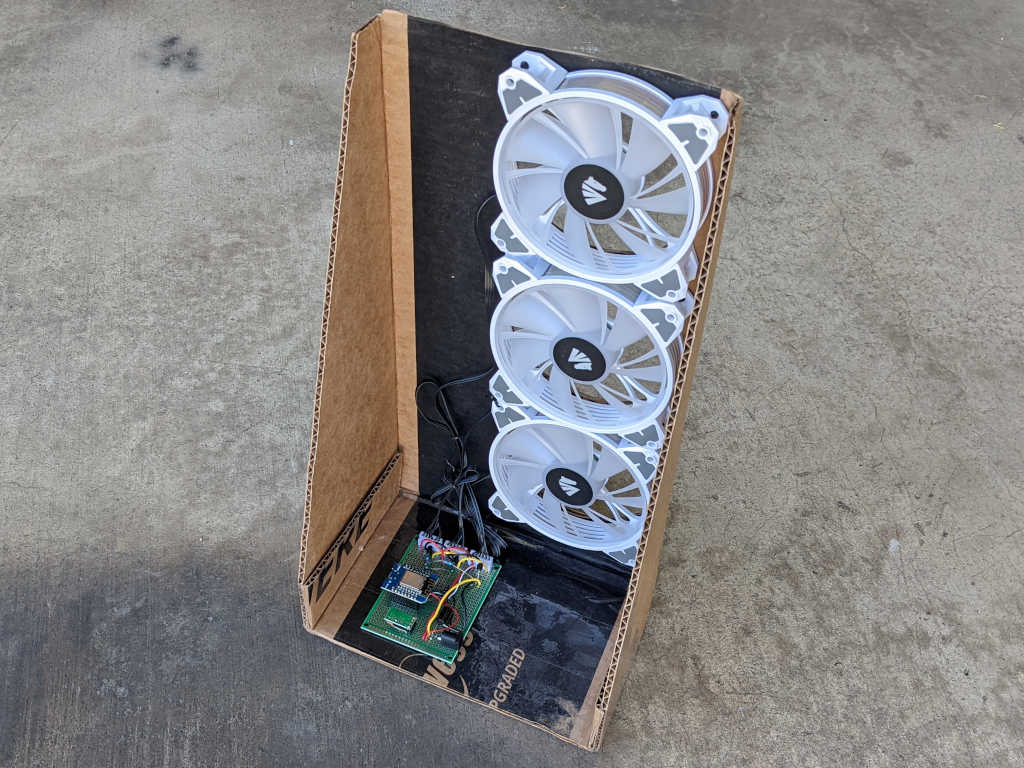
I took apart the Asiahorse Magic-i 120 V2 control hub and remote because I didn’t need them anymore: I could control its trio of fans with my own circuit board. How shall I wield such power? It was fun playing with 3D coordinate mapping with a Pixelblaze, but my most immediate need is a lot less exciting: combination bedside fan and light to replace my first bedside fan project. (Which didn’t have a light.)
For such a simple use, the power of a Pixelblaze is overkill. So, my board was modified to use an ESP8266 (Wemos D1 Mini module) as its brain, running ESPHome for integration with Home Assistant. In the Pixelblaze demo, the fans were always on. Now they will be controlled by that ESP8266 as well.
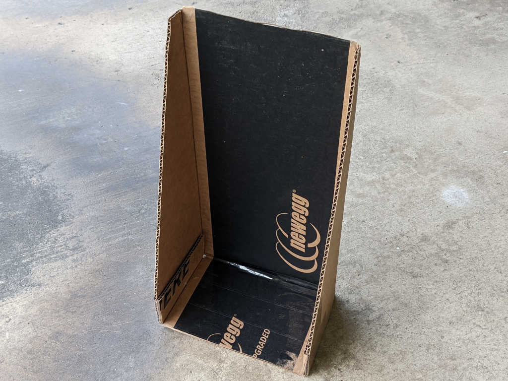
I’m still not settled enough on the idea to spend the time designing and 3D printing a proper frame, but at least I’ve put a bit more effort into this cardboard creation. I’m reusing a corner of a Newegg shipping box (I think it was the very box used to ship the Asiahorse fan bundle) and I’ve turned it inside out so at least I don’t have to stare at the Newegg logo every time I’m in bed.
Three large holes, one per fan, was cut from that cardboard for airflow. Twelve more holes, four per fan, were drilled into the cardboard for fan mounting screws. The physical assembly came together quickly, but there were a few more hiccups.
First problem was that FastLED, the addressable LED Arduino library used by ESPHome, is not compatible with the latest Arduino 3 framework at the time of this writing. Relevant ESPHome documentation page listed the issues as 1264 and 1322 filed against FastLED Github repository. Until they are resolved, ESPHome offers a workaround for compiling against Arduino framework 2.7.4. Which is what I did to run these WS2812 LEDs. For the first draft, I’m not going to use the addressable nature at all, just a single solid color. I think it would be cool to have a falling waterfall pattern on these lights, but that’ll be experimentation for later.
The second problem is that PWM control of fan speed results in an audible whine, probably an 1kHz whine which is the practical maximum speed for ESP8266 software PWM. The previous fan project removed the audible whine by adding a capacitor to smooth out voltage output. I could do that again, one capacitor per fan, but these fans run quietly enough at full speed I’m willing to skip PWM and have just on/off control.
The final problem is that I still want this fan to be responsive to temperature changes, turn itself off in the middle of the night when it got cool enough. I wasn’t happy with the TMP36 sensor I bought for the previous experiment, so now I’m going to try another sensor: the DS18B20.
This quick and easy project produces a quiet breeze for hot summer nights. I wanted something gentler than the fans already in the house, and I wanted it to automatically turn itself off in the middle of the night once things cooled down enough. It also let me apply lessons I’ve recently learned. Even though I’ve found that the TMP36 sensor isn’t a great fit for a ESP8266, it’s something already on hand for an ESP8266 to tell if it’s cool enough to turn the fan off.
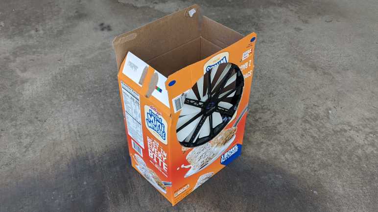
The 3-wire fan is a PC cooling fan with a 200mm diameter, relatively large within that category. I bought it some years ago for my first Luggable PC project, it was just a bit too large for that purpose and sat idle until now. I thought about designing and 3D-printing a stand for this fan, but in the spirit of keeping things simple and quick, I mounted it in an empty cereal box instead. Cutting holes in the box to accommodate the fan took a tiny fraction of the time it would have taken to 3D-print something.
Primary air intake was the top of the box, left open.
I cut a smaller secondary air intake towards the bottom of the box, which also makes it easy to toss my control board in there and feed it power from a salvaged DC power supply. A TMP36 sensor was soldered in the farthest corner in this picture, visible sticking up vertically.
Results
Running ESPHome (YAML excerpt below) this project successfully controls fan speed via ESP8266 PWM. It was also able to read temperature via TMP36 sensor, but values were affected by ESP8266. Located 1/2 of the circuit board away plus the entire height of its legs was not enough distance from the ESP8266 heat island: temperature reading dropped noticeably whenever the fan is turning. Still, it’s enough for me to create a Home Assistant automation to turn off this fan whenever the temperature dropped below a certain threshold. Due to the heating from ESP8266, the temperature value rises a few degrees immediately after the fan was turned off. Thankfully there was no risk of system feedback oscillation, because I did not create an automation to turn the fan on — I do that manually when I’m ready for a light breeze.
This worked well sitting on my bedstand, creating a light cool breeze when I’m ready to fall asleep and turning itself off while I was asleep. But its physical footprint was a problem: it took up space that is ideally used for a bedstand light. The obvious solution was to pull some LEDs into the next version, which is an opportunity to tackle another item on my to-learn list: PC accessories with embedded RGB LEDs.
ESPHome YAML to read TMP36 temperature and fan speed every 5 minutes:
After successfully building a small circuit for 3-pin fan PWM control, I decided to add a temperature sensor. Now I have the option to make it smarter about adjusting speed (or stopping entirely) based on temperature. There are many temperatures sensor options, I decided to start simply and inexpensively with a sensor that returns an analog voltage representing temperature. A batch of TMP36 (*) seemed like a good starting point.
According to the Analog Devices datasheet, TMP36 output pin voltage is 0.75V at 25 degrees Celsius. For every degree of temperature rise, voltage increases 0.01V. For my first draft I wired it to my Wemos D1 Mini module’s analog input pin. But I had to adjust the scaling because a D1 Mini includes a voltage divider to scale input of 0-3.3V down to ESP8266 ADC range of 0-1V. This voltage divider (and math necessary to convert it back) added error to the reading. Since I intend to use this sensor for measuring room temperature, I do not expect to measure above 50 degrees Celsius (122 Farenheit) which corresponded to 1 Volt. Thus, I soldered a wire to connect TMP36 signal directly to ESP8266 module analog input, bypassing the voltage divider.
I noticed that there appears to be a startup time period where the temperature reading is 2-3 degrees too high but, after about 5-10 minutes, it will drop to a steady state temperature and stay there. I’m not sure if this startup behavior is from the TMP36 sensor or from the ESP8266 ADC. Either way, it meant I could not use this sensor in a sleep/read/sleep/read cycle because such a quick read will always result in a too-high value from this startup behavior.
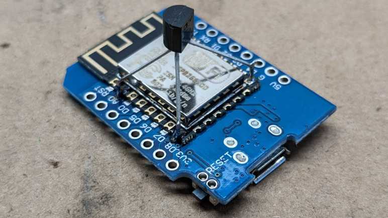
With the initial breadboard test complete, I built a dedicated temperature sensor node with just an ESP8266 with a TMP36. In the interest of compactness, I decided to solder the sensor directly to ESP8266 module pins.
Upon startup, I saw that it reported temperature that was a few degrees too high, but I thought that was just the startup behavior I already noticed. But instead of dropping, it had kept going up. I thought I had a bad TMP36 until I realized it was accurately reading heat generated by a running ESP8266. According to my USB power meter, it consumed less than a third of a Watt, but that’s plenty of heat for a directly-mounted TMP36 to pick up.
If I wanted to measure a room’s air temperature and not temperature of a running ESP8266, I needed to give the sensor some distance. But even then, the readings weren’t reliable.
A little web research taught me that the ESP8266 ADC isn’t very precise nor is it calibrated. For most applications, being off by a few hundredth of a volt is a negligible error, but here every hundredth of a volt represents an entire degree of temperature which is decidedly not negligible. Taking multiple values and averaging them did help with the precision, but not accuracy. Knowing what I know now, in hindsight I should have done this with an ESP32. Those chips (or at least newer units) have their ADCs calibrated at Espressif factory. Though it is more likely that I will try a different temperature sensor in a future project. Either way, right now I have TMP36 on hand with a circuit board suitable for controlling 3-wire PC cooling fans. Time to put them together to do something useful.
Even though it doesn’t work very well, here’s an ESPHome YAML excerpt anyway. This will read a TMP36 every second and report average value every five minutes. TMP36 signal is assumed to have been soldered directly to ESP8266 analog input, bypassing Wemos D1 Mini voltage divider.
It was neat that I could control the speed of a 4-wire CPU cooling fan with just software a PWM signal from an ESP8266, but 4-pin fans with built-in power switching are in the minority. Most available fans have no built-in speed control and depend on external PWM circuitry to vary their input voltage level. If I wanted to control speed of such fans with an ESP8266, I’ll need to get a power transistor of some sort into the circuit.
I’ve found several tutorials online for fan speed control via PWM, but they all use a transistor on low side of the fan. They do this because it makes the circuit easier. We connect the black fan wire to collector of the transistor, connect emitter to ground, and finally connect PWM signal from our microcontroller to transistor base. This will work because the transistor and the microcontroller share a common ground. A transistor needs only a volt or so on the base pin, easily delivered from any microcontroller.
The problem with this approach is that we could no longer directly read the tachometer signal of 3-pin fans, because they are open-drain to the “ground” which is no longer ground but low side of the fan. Depending on implementation details on the fan, the voltage level on that pin may rise too high for the microcontroller.
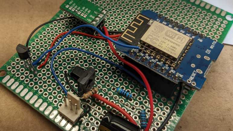
There are many valid ways to resolve this situation, the path I chose is to use a PC817 optocoupler. (*) Internally it is a LED pointed at a receiver. This optical system transmits a signal while electrically separating LED side from receiver side. In my case this I no longer need a common ground.
From here, there are two options forward: I could use the optocoupler to read the tachometer signals, or I could use the optocoupler to put the transistor on the fan’s high side. I chose to switch the fan’s high side so the fan has a common ground with the microcontroller, and I could directly read tachometer signal. Of course, it is valid to use optocoupler on both motor power PWM and for tachometer feedback. This is necessary for electrically noisy motor systems, but the brushless fan of a computer cooling fan (usually) does not require such measures.
I did have to add a capacitor to smooth out my PWM output, but that would have been necessary in any case. Having full PWM control means I can now switch the fan off completely with a 0% duty cycle, but it also means I am responsible for avoiding low PWM levels where a fan could not turn and stalls. After I proved I had PWM control via Home Assistant UI, I thought it would be fun to have the option to control fan based on temperature, so I added a TMP36 sensor.
ESPHome YAML excerpt for basic PWM fan control and reading fan tachometer. Note: this simple example lacks intelligence to avoid low PWM levels that would stall a fan.
I got curious about how the 4 wires of a CPU cooling fan interfaced with a PC motherboard. After reading the specification, I decided to get hands-on.
I dug up several retired 4-wire CPU fans I had kept. All of these were in-box coolers bundled with various Intel CPUs. And despite the common shape and Intel brand sticker, they were made by three different companies listed at the bottom line of each label: Nidec, Delta, and Foxconn.
I will use an ESP8266 to control these fans running ESPHome, because all relevant code has already been built and ready to go:
Tachometer output can be read with the pulse counter peripheral. Though I do have to divide by two (multiply by 0.5) because the spec said there are two pulses per fan revolution.
The ESP8266 PWM peripheral is a software implementation with a maximum usable frequency of roughly 1kHz, slower than specified requirement. If this is insufficient, I can upgrade to an ESP32 which has hardware PWM peripheral capable of running 25kHz.
Finally, a PWM fan speed control component, so I can change PWM duty cycle from HomeAssistant web UI.
One upside of the PWM MOSFET built into the fan is that I don’t have to wire one up in my test circuit. The fan header pins were wired as follows:
Black wire to circuit ground.
Yellow wire to +12V power supply.
Green wire is tachometer output. Connected to a 1kΩ pull-up resistor and GPIO12. (D6 on a Wemos D1 Mini.)
Blue wire is PWM control input. Connected to a 1kΩ current-limiting resistor and GPIO14. (D5 on Wemos D1 Mini.)
I was not able to turn off any of these fans with a 0% duty cycle. (Emulating pulling PWM pin low.) All three kept spinning.
The Nidec fan ignored my PWM signal, presumably because 1 kHz PWM was well outside the specified 25kHz. It acted the same as when the PWM line was left floating.
The Delta fan spun slowed linearly down to roughly 35% duty cycle and was roughly 30% of full speed. Below that duty cycle, it remained at 30% of full speed.
The Foxconn fan spun down to roughly 25% duty cycle and was roughly 50% of the speed. I thought it was interesting that this fan responded to a wider range of PWM duty cycles but translated that to a narrower range of actual fan speeds. Furthermore, 100% duty cycle was not actually the maximum speed of this fan. Upon initial power up, this fan would spin up to a very high speed (judged by its sound) before settling down to a significantly slower speed that it treated as “100% duty cycle” speed. Was this intended as some sort of “blow out dust” cleaning cycle?
These are not closed-loop feedback devices trying to maintain a target speed. If I set 50% duty cycle and started reducing power supply voltage below 12V, the fan controller will not compensate. Fan speed will drop alongside voltage.
Playing with these 4-pin fans were fun, but majority of cooling fans in this market do not have built-in power transistors for PWM control. I went back to learn how to control those fans.
I’ve mapped out the segments of a small LCD salvaged from an electric blanket controller. I activated these segments with an ESP8266 that alternated between 0V and 3.3V on two GPIO pins. Good for individual segments, but not good enough to drive the whole display. There are eight segment pins and two common pins for 8*2=16 total possible combinations (14 of which are used for the two 7-segment digits) controlled from ten total pins.
Technically speaking, an ESP8266 has enough GPIO pins, but we’d start intruding into the realm of sharing pins between multiple tasks which is more complexity than I wanted to tackle for a quick test. When driving a LCD, we also want to control voltage levels on these pins and ESP8266 lacks hardware PWM peripheral. For these reasons I will use an ESP32. It has more than enough pins, and hardware PWM peripherals to support generating a voltage on all those pins. ESP32 LEDC PWM peripheral is very flexible, and I need to determine how I want to configure that peripheral.
I used ESPHome because it is a great platform for quick experiments like this. I don’t strictly need WiFi here, but easy integration to Home Assistant and ability to update code over the network are great conveniences. Before I found ESPHome, I would wire up a few potentiometers to the circuit board and write code to use ADC to read their positions. A bit of code will then allow me to interactively play with parameters and see their results. But now, with ESPHome in my toolbox, I don’t need to solder potentiometers or write code for ADC. I can get such interactivity from the Home Assistant dashboard.
By default, ESPHome configures LEDC PWM peripheral to run at a frequency of 1kHz. According to Espressif documentation, it can be configured to run as high as 40MHz, though at that point it really isn’t a “PWM” signal anymore with only a fixed 50% duty cycle. Slowing down the frequency increases the number of bits available for duty cycle specification, and I wanted to find a tradeoff that I think will work well for this project. Here is an excerpt of ESPHome configuration YAML I used for this test.
This allows me to adjust two variables, each exposed to Home Assistant as a monochromatic dimmable light. Which I can change via a slider on a web page instead of a potentiometer soldered to the board. (The gamma correction value was set to 1.0 because we’re not actually controlling a visible light that requires gamma correction.)
pwm_23 controls the PWM duty cycle.
pwm_freq controls the PWM frequency via ESPHome Template Lambda. Theoretically from 1kHz to 10MHz, though in practice we won’t reach either end as the state never gets all the way down to 0.0 nor all the way up to 1.0.
As I adjusted the frequency, ESPHome automatically calculates the duty cycle bit depth.
[15:32:00][D][ledc.output:041]: Calculating resolution bit-depth for frequency 2491148.000000
[15:32:00][D][ledc.output:046]: Resolution calculated as 5
[15:32:00][D][ledc.output:041]: Calculating resolution bit-depth for frequency 2494322.000000
[15:32:00][D][ledc.output:046]: Resolution calculated as 5
[15:32:00][D][ledc.output:041]: Calculating resolution bit-depth for frequency 2497869.000000
[15:32:00][D][ledc.output:046]: Resolution calculated as 5
[15:32:00][D][ledc.output:041]: Calculating resolution bit-depth for frequency 2501411.000000
[15:32:00][D][ledc.output:046]: Resolution calculated as 4
[15:32:00][D][ledc.output:041]: Calculating resolution bit-depth for frequency 2503623.000000
[15:32:00][D][ledc.output:046]: Resolution calculated as 4
[15:32:00][D][ledc.output:041]: Calculating resolution bit-depth for frequency 2505428.000000
[15:32:00][D][ledc.output:046]: Resolution calculated as 4
From this snippet, we can see that 2.5MHz is the limit for 5 bits of resolution. 25 = 32 levels, which gives me control of resulting voltage in (3.3V / 32) ~= 0.1V increments. I think that’ll be good enough.
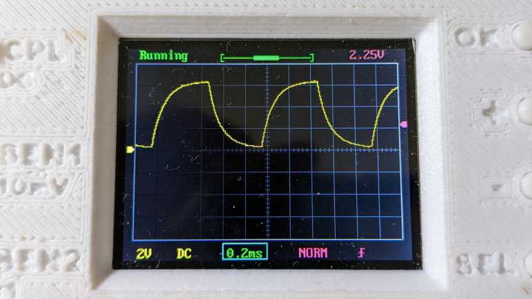
Here are some plots in oscilloscope form: First the starting point of 50% duty cycle at default 1kHz frequency, before and after adding a 100nF capacitor into the mix.
Not nearly good enough to output 1.65V. To make this better, I can increase the capacitance or increase frequency. Increasing capacitance will dull system response (and I need pretty quick response to rapidly cycle between LCD common pins) so I start cranking up the frequency.
At hundreds of kilohertz without capacitor, the resulting wave is more than what this little oscilloscope can capture at this timescale. When the 100nF capacitor is added in, we see a pretty respectable 1.65V signal, might even be good enough. But there’s plenty of room left to go faster.
Getting into the megahertz range, there’s enough natural capacitance in the system (wires, breadboard, etc.) that we see a pretty good waveform even without a real capacitor in line with the output. But with just a 330pF capacitor (much smaller than the 100nF I started with) the resulting voltage looks pretty good. At least, at this time scale. Now I need to move beyond ESPHome for better control of 2.5MHz PWM signals.
Once I had Mr Robot Badge Mk. 2 up and running on Arduino, I thought: what about Home Assistant? After all, ESPHome is built on compiling ESP8266 Arduino Core code using PlatformIO command-line tools. The challenging part of ESPHome is always that initial firmware flash, which I’m already set up to do, and after that I could do updates wirelessly.
I started easy: getting badge buttons to be recognized as binary sensors in Home Assistant.
Piece of cake! Now on to the more interesting (and more challenging) part: using the LEDs. I followed ESPHome examples to create a custom component. This exposed a single custom output that treated the entire array as a single color (monochromatic) dimmable light.
C header file with custom class declaration:
#include "esphome.h"
#include "Adafruit_IS31FL3741.h"
using namespace esphome;

class MrRobotBadgeFloatOutput : public Component, public FloatOutput
{
    Adafruit_IS31FL3741 ledArray;

    public:
        void setup() override
        {
            ledArray.begin();
            ledArray.setLEDscaling(0x3F); // 25% of max
            ledArray.setGlobalCurrent(0x3F); // 25% of max
            ledArray.enable(true);  // bring out of shutdown
        }

        void write_state(float state) override
        {
            int8_t value = state * 128; // 50% of max
            ledArray.fill(value);
        }
};
Tada! I’m back at the same test I had using Arduino, lighting up all the pixels to highlight problematic LEDs.
The next step in this progression is to expose the entire 18×18 array as individually addressable pixels. Doing so would allow using ESPHome’s display rendering engine to draw text and graphics, much as Adafruit GFX does. I found the Addressable Light base class but I got stuck trying to make it happen. I’ve had no luck finding examples on how to implement a custom addressable light, and didn’t get much of anywhere bumping my head in the dark. Digging through existing Addressable Light implementations on GitHub, I’ve found many object classes that may or may not be required to implement my own addressable light.
I imagine there’s an architecture diagram somewhere that describes how these components interact, but my search has come up empty so far and there’s not much in the way of code comments. Most of the online discussions about addressable LED pixels in Home Assistant are centered around WLED, which as of this writing does not support the IS31LF3741 control chip. I’m going to put further exploration on hold until I have more experience with ESPHome custom components to understand their object hierarchy.
The idea is a very simple shooting game. I will add an LED to the breadboard connected to GPIO 18. I will count to five seconds in an on_loop lambda and illuminate the LED using ESPHome GPIO output component. Once illuminated, it will wait for the signal sent by a Roku RC108 remote when the “OK” button is pressed. Once received, I will darken the LED for five seconds before turning it back on. With this very simple game I pretend to “shoot out” the light with my remote.
It was silly and trivially easy as far as shooting games go. Infrared remote controls are designed so the couch potato doesn’t have to aim very accurately for them to work. The emitter sends out the signal in a very wide cone, and the receiver is also happy to receive that signal from within a wide cone. If I am to evolve this into an actually challenging target practice contraption, I would have to figure out how to narrow the cone of effectiveness on the emitter, or the receiver, or both!
But that was not the objective today. Today it was all about dipping my toes in that world before I continued with my Roku teardown. I wanted to keep the hardware trivial and the code simple, so here is the ESPHome code excerpt for this super easy shooting game:
Looking over the circuit board of a Roku Premiere 4620X (“Cooper”) I saw a lot of things that might be fun to play with but require more skill than I have at the moment. But that’s fine, every electronics hobbyist has to start somewhere, so I’m going to start small with the infrared remote control subsystem.
Consumer infrared (IR) is not standardized, and signals may be sent on several different wavelengths. Since I want to play with the Roku RC108 remote control unit, I needed to remove the infrared receiver of its corresponding Premiere 4620X in order to guarantee I have a matching set. This is a small surface-mount device protected by a small metal shield that I could fold out of the way.
Once the shield was out of the way, I could turn on the Roku and probe its pins with my voltmeter to determine the power supply pin (constant 3.3V) the ground pin, and the signal pin (mostly 3.3V but would drop as I sent signals with the remote.) I then removed this receiver with my soldering iron and connect this tiny part to a set of 0.1″ spacing headers so I could play with it on a breadboard.
In this picture, from top to bottom the pins are:
Ground
(Not connected)
Power 3.3V
(Not connected)
Active-low signal
I installed it on a breadboard with an ESP32, flashed with ESPHome which is my current favorite way to explore things. In this case, ESPHome has a Remote Receiver component that has decoders for many popular infrared protocols. What if we don’t know which decoder to use? That’s fine, we can set the dump parameter to all which will try every decoder all at once. For this experiment I chose an ESP32 because the of its dedicated remote control (RMT) peripheral for accurate timing while decoding signals. After I get something up and running, I might see if it works on an ESP8266 without the RMT peripheral.
With dump parameter set to all listening to a Roku RC108, I got hits from the JVC, LG, and NEC decoders. And occasionally I would get a RAW message when none of them could understand the signal. If I hold the [up] button, I get one instance of:
[18:55:50][D][remote.jvc:049]: Received JVC: data=0x5743
[18:55:50][D][remote.lg:054]: Received LG: data=0x57439867, nbits=32
[18:55:50][D][remote.nec:070]: Received NEC: address=0xC2EA, command=0xE619
But just the first one. All following hits look like this, and they repeat for as long as I held down the [up] button.
[18:55:50][D][remote.jvc:049]: Received JVC: data=0x5743
[18:55:50][D][remote.lg:054]: Received LG: data=0x57439966, nbits=32
[18:55:50][D][remote.nec:070]: Received NEC: address=0xC2EA, command=0x6699
Then if I press the [down] button on the remote, the first interpreted signal became:
[18:55:52][D][remote.jvc:049]: Received JVC: data=0x5743
[18:55:52][D][remote.lg:054]: Received LG: data=0x5743CC33, nbits=32
[18:55:52][D][remote.nec:070]: Received NEC: address=0xC2EA, command=0xCC33
Then it would repeat the following for as long as [down] was held:
[18:55:53][D][remote.jvc:049]: Received JVC: data=0x5743
[18:55:53][D][remote.lg:054]: Received LG: data=0x5743CD32, nbits=32
[18:55:53][D][remote.nec:070]: Received NEC: address=0xC2EA, command=0x4CB3
Looking at this, it looks like JVC is overeager and doesn’t actually understand the protocol as it failed to differentiate up from down. That leaves LG and NEC decoders. To find out which is closer to the Roku protocol, I started tightening the tolerance parameter from its default of 25%. When I have it tightened to 10%, only the NEC decoder returned results. Even better, each button returns a repeatable and consistent number that is different from all of the others. Even if Roku isn’t actually using a NEC protocol, using the NEC decoder is good enough to understand all its buttons. I used the NEC decoder to generate this lookup table.
Roku Remote Button
Decoded Command
Back
0x19E6
Home
0x7C83
Up
0x6699
Left
0x619E
OK
0x55AA
Right
0x52AD
Down
0x4CB3
Instant Replay
0x07F8
Options
0x1EE1
Rewind
0x4BB4
Pause
0x33CC
Fast Forward
0x2AD5
Netflix
0x34CB
Sling
0x58A7
Hulu
0x32CD
Vudu
0x7788
I think I got lucky this time with the NEC decoder. I had another infrared remote control in my pile of electronics (JVC RM-RK52) and none of the ESPHome decoders could decipher it, just RAW data all the time. Alternatively, it’s possible that remote is on a different infrared wavelength and thus this particular receiver is only picking up fringe gibberish. I’ll put the JVC remote back in the pile until I am in the mood to dig deeper, because right now I want to quickly play with this salvaged infrared system.