Canon Pixma MX340 Teardown Phase 1 Complete

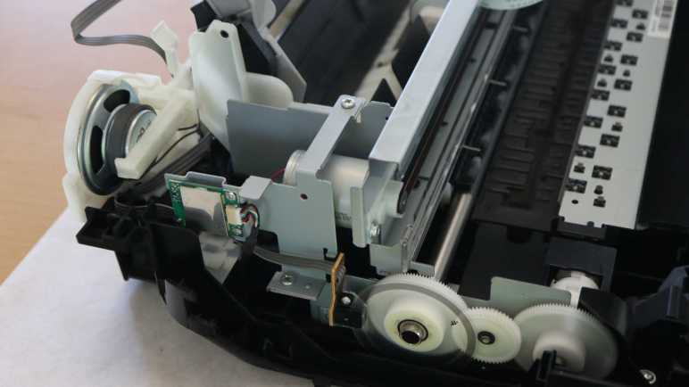
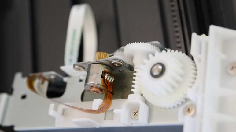
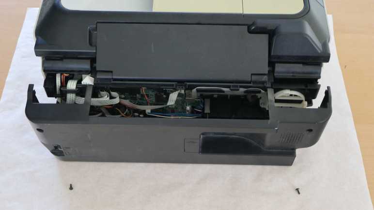
Working my way around the base of a Canon Pixma MX340 multi-function inkjet, removing panels and exposing components, I think I’ve reached a good stopping point. After disassembling the components behind the print head carriage motor, I have access to everything with an electric wire or cable attachment to the main control board. This is a good place to pause mechanical disassembly, and switch focus to probing electrically and see what I can learn. This marks the transition from phase 1 to phase 2 in my original 3-phase teardown plan.

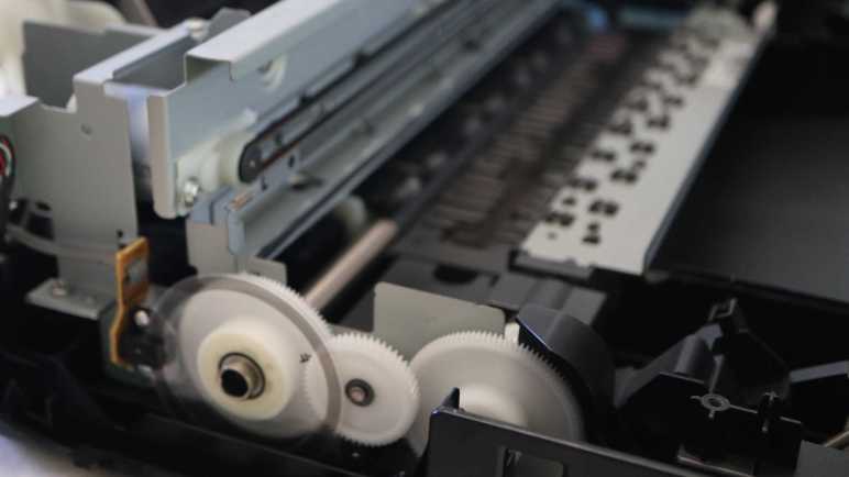
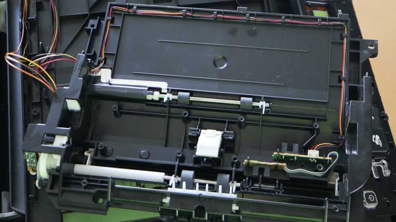
There are still many fascinating mechanisms I have not yet explored, most of which are behind the print head parking area. It is home to at least two paper-handling functions: one to kick out the base of the paper feed tray, so the topmost sheet makes contact with the large central paper feed roller. Then another mechanism to turn that roller and feed a sheet into the print path. I also saw what looked like flexible tubes down there and I don’t know what they do yet.

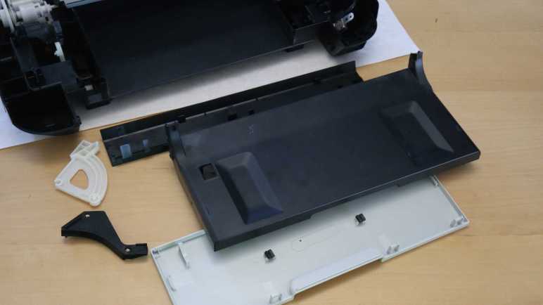
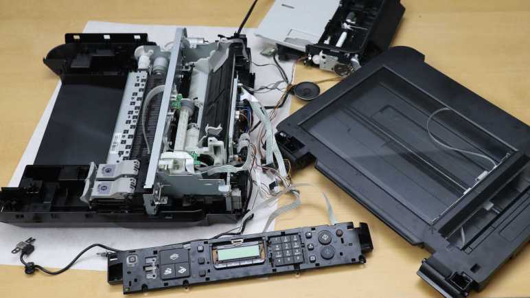
I think I know which screws I need to remove to access those mechanisms and get some answers, but I’m not sure if the printer will still function if I do. Right now, all the major components of this MX340 are laid out on a large desk (the scattered layout is too large to fit on my usual electronics workbench) and everything still runs. The document feeder can feed sheets of paper, the scanner can scan, and the inkjet can print. Taking the printer further apart may damage functionality, so I’ll postpone further disassembly until after I’ve learned what I can from electrically probing the printer while it is running.

What do I hope to learn? Well, I know I won’t understand everything. Part of why I have a collection of inkjet printers is that I had been waiting until I’ve learned enough to decipher all of the electronic details, letting the collection grow. But I’ve decided it’s OK if I can’t decipher everything. So I will scope phase 2 of my project with reasonable expectations and a plan.


This teardown ran far longer than I originally thought it would. Click here for the starting point.

Canon Pixma MX340 Print Head Motor Area

I’m taking apart a Canon Pixma MX340 multi-function inkjet and finding fascinating details everywhere. Including a mechanism that automatically opens the door to the print output tray by tapping into torque from the paper feed motor.

Above and behind (to the left in this picture) the paper feed motor is the print head carriage motor, these two motors work together for complete control in two dimensions for printing across the entire page. The actual motor units look like they might be mechanically identical units, it’s hard to tell for sure until further disassembly. Both are under closed-loop control.

In comparison to the paper feed motor’s encoder disk, the print head motor has a encoder strip across the width of the printer in front of its drive belt. A spring pulls the strip tight so it does not sag.

Here’s a close-up view of the encoder strip. Again, no fancy patterns, just an alternating strip of black and clear. The black dot to the left may be part of a position sensing homing mechanism. The sensor to read this encoder strip is probably part of the print head assembly, something to look for later when I take that piece apart.

Next to the motor is a small circuit board, about the size of a large postage stamp, sitting all by itself on a metal bracket. Connected to the mainboard with a six-wire harness, most of it is covered up by a metal shield.

Releasing three screws and flipping it over uncovers the product label telling us it is the WLAN Module. Its left-rear position is interesting. I know motors generate a lot of electromagnetic noise, and this is the area where the print head and paper feed motors live. Almost directly overhead is the stepper motor to drive the automatic document feeder. Sitting in close proximity to motors, this is about the last place I expected to find a module for wireless radio frequency communication! I would have guessed such a thing would have lived in the front right corner, near the USB port, putting it as far away from the motors as possible. But as I can see here, the Canon engineers decided differently. Apparently there is some criteria more important than “keep the RF antenna away from sources of RF noise”, but I don’t know what it might be.

Behind the motor and WiFi module is the speaker assembly. At first I was confused to find a full speaker here, as most of the audio feedback came from simple beeps and I had expected to find a small piezo buzzer either on the front control panel circuit board or on the main circuit board in the back. A few minutes later it clicked: one of the multiple functions is a fax machine. If we’ve accidentally dialed a voice line and a human being picked up, we need to be able to hear their confused “Hello?” to realize our mistake.

With disassembly of the speaker and WLAN module assemblies, I now have access to all the electrical wiring I could see inside this machine. Time to pause working with screwdrivers and pull out the oscilloscope.


This teardown ran far longer than I originally thought it would. Click here for the starting point.

Canon Pixma MX340 Paper Output Tray Door

I’m taking apart a Canon Pixma MX340 multi-function inkjet and I’ve found a lot of clever mechanisms that allow a single motor to activate multiple different functions. In this example, the paper feed motor does more than just feed paper.

There is a door in front of the printer below the control panel. It is usually kept closed when the printer is not in use. It help keep dust out of the printer mechanisms and also presents an aesthetically clean face when not printing. Once opened, the door becomes part of the paper output tray. I usually remember to pry the door open whenever I start a print job on this printer, but one time I forgot to do so as the printer whirred to life. Before I realized my mistake, I was startled by the sound of the printer popping the door open by itself. I had been curious how this was done, because I doubt it would be cost-effective to include a motor just to actuate this door. Now I can look at the details of this mechanism for opening the door using the paper feed motor.

Here’s the mechanical linkage responsible for this magic. In these pictures, the camera is looking from the printer’s side. The door is to our right and the paper feeds from our left. The picture on the left depicts the system when the door is closed state, the picture on the right is when the door is open.

Tracing it further back, I saw the pop-open mechanism is under this black plastic cover, removed after releasing two fasteners. Removing the cover also uncovered the motor driving this gearbox, confirming it is a DC motor and appears to be a commodity component.

How does the paper feed roller shaft pop open the front door? Power is transmitted via this pin in the shaft, rigidly coupling the right-most piece of plastic to the shaft.

I count at least three, possibly more, other pieces of plastic adjacent to the pinned piece. They lack the pin and thus could spin freely on the shaft. As the paper feed roll rolls forward, tabs on each plastic piece would have a bit of freedom to rotate before engaging the next piece in the sequence. The door opening mechanism is connected to a paddle (circled in red) that rests against the left-most segments.

As each piece spins and engages the next, we start seeing the slot that will engage with the paddle.

As the pieces kept turning, the slot (divided across two pieces) line up and the paddle falls in to the slot. This blocks the left-most two pieces of plastic from turning until the paddle moves.

But the motor is quite powerful, so it pushes the paddle away, which opens the door. As the door flop down to become part of the paper output tray, the paddle pulls further away from the shaft.

There weren’t much else to the front door other than its automatic opening mechanism. I found it was clipped together and fairly straightforward to take apart into its component plastic pieces.

The open question I have about this mechanism is the fact it incorporated several interlocking pieces that all have to engage and connect before the door opens. In practice, this means the paper feed roller turns several rotations before the door opens. Versus an easy single-piece implementation that would have opened the door as soon as the paper feed roller starts spinning forward. Why does this complexity exist? I think the answer has to do with the gearbox behind the print head parking area, so it’s a mystery I’ll put on hold for the moment. There are other, more easily accessible, things to look at like the print head carriage motor and nearby components.


This teardown ran far longer than I originally thought it would. Click here for the starting point.

Canon Pixma MX340 Paper Feed Motor Gearbox

I know I haven’t uncovered all of the paper handling mechanisms of this Canon Pixma MX340 I’m taking apart, but I’m already impressed with the partial overview I’ve got so far. Right now my focus is tracing those paper feed rollers back to the motor gearbox driving them.

There are two paper feed rollers visible here, one before and one after the printing area. Each of those roller shafts are attached to a large white gear. A smaller intermediate gear sits between them to drive both. Earlier I had thought the motor must be behind that center gear, but it turned out the motor was actually a little lower.

The motor output shaft has a small black plastic gear, almost blending into the shadows. I traced only two wires leading into this area, implying it’s a brushed DC motor down there. Some of the older inkjet printers I took apart earlier used stepper motors for open-loop control. In this printer, precise control is accomplished with a closed-loop control system: the gear on the left has an encoder wheel and a sensor reading its motion providing feedback.

Flipping my camera lens to “super macro” mode, I got this close-up picture of the encoder ring. It is series of very fine evenly spaced radial lines, consistent with an incremental encoder. I see four wires leading to the sensor, consistent with things I expect to see: power, ground, A, and B. I’ll hook them up to my oscilloscope later to verify this deduction.

This motor drives a lot more than the two paper feed rollers immediately adjacent to the print area. One of the paper feed rollers transmit its power all the way across the printer to a gearbox behind the print head parking area. It’s likely involved in feeding paper from the input tray, and others I look forward to deciphering later. Right now, though, another interesting feature of this printer is immediately adjacent and accessible.


This teardown ran far longer than I originally thought it would. Click here for the starting point.

Canon Pixma MX340 Paper Path

I’m taking apart a Canon Pixma MX340 multi-function inkjet and it took a while to work my way down to the actual printing mechanisms in its base. There were a lot of interesting parts near the print head parking area, including a mystery gearbox I can’t access until later. For now I know only it has several gears and a photo interrupter sensor, and it’s involved in the paper feed process.

One of the gears is connected via a shaft to the paper feed roller, which has its own corresponding spring-loaded lever + photo interrupter sensor to detect when a sheet of paper has been fed through.

The tired old paper feed roller is covered with cracks.

The paper feed path design for this printer is nearly straight, barely bending the sheet of paper as it is fed from the input tray in the back through to the printing area and the output tray in the front. Here we can see two more sets of rollers, one immediately before and immediately after where the print head deposits ink.

Between these two sets of rollers, underneath that print area, is a sponge-looking substance that has soaked up a visible quantity of ink. The surrounding plastic shows plenty of ink stain discoloration as well. I can’t explain all of the reasons why ink ended up here instead of on paper, but I know one explanation are from my border-less photo printing on 4″ x 6″ glossy photo paper. In order to not leave any borders, the print head shoots out extra ink beyond the paper’s edge. That ink had to be go somewhere and we’re looking at them now.

Now that I know excess ink may get sprayed around even during normal usage, I started noticing ink absorption pads scattered throughout the print engine. I remember reading consumer backlash against Epson EcoTank machines. Advertised to be ideal for high volume inkjet printing, some users were surprised when their machines stopped printing. They had encountered a preprogrammed expiration for ink pads reaching end of life. At the time I agreed with many others online thinking it was just corporate greed shutting down perfectly working printers, but now that I’m looking at these ink pads on my old printer, maybe it’s a good idea to avoid overfilling their diapers.

The second set of paper feed rollers helps keep the paper straight during printing, and can help eject the printed sheet at the end. But it needs to solve an unique problem: how does it handle the printout when the ink is still damp immediately after printing? To see how that was done, I unscrewed the top set of rollers and flipped over the mechanism for a closer look.

The top rollers are actually small stamped sheet metal spiked wheels that minimize contact area with the just-printed surface. Thereby avoid smearing still-wet ink as the paper travels through these rollers. Very nice! Next I will look at the motor and gears driving this paper feed mechanism.


This teardown ran far longer than I originally thought it would. Click here for the starting point.

Canon Pixma MX340 Print Head Parking Area

The flatbed scanner module of this Canon Pixma MX340 multi-function inkjet turned out to be mostly empty space, which should hopefully ease a more detailed investigation later. Removing the scanner also unblocked the fasteners I saw earlier, allowing me to finally disassemble the base of this machine for a look inside.

I opened the base enclosure starting from its front right corner, where I found a very sturdily installed USB port. I remember this machine had the ability to scan straight to a PDF on a USB flash drive in this port, which was quite the lifesaver in the few times I needed that capability and needed it now. Behind the USB port is a thin sheet of clear plastic attached with double-sided adhesive. It looks like a shield… but against what?

I could see the USB port and shield is in front of where the print head carriage assembly is parked when it is not printing. I guess this shield is protecting the USB port from any errant ink drops that may spray from behind. I can see how we wouldn’t want ink to drip out of the USB port onto our flash drives, but I didn’t even know splashing ink was a risk.

Then I took a closer look at the print head parking area and saw ink-stained components underneath it. Oh yeah, I now see there’s plenty of ink splash risk.

I pushed the print head carriage out of the way for a closer look at what lies beneath. There’s a lot of ink stain from years of service. It’s pretty clear the black cartridge lives on the right and the color cartridge on the left. For the color cartridge, it looks like the blue ink comes out of the left side and the yellow ink comes out the right. Curiously, I don’t see much in the way of red ink (or more likely magenta) even though I would have thought red would leave the brightest stains.

The front-most white gear, heavily stained blue, is attached to one of two paper feed roller shafts. I can see it meshes with gears further back, but I couldn’t see exactly what’s going on down there without further disassembly. The most intriguing feature that caught my attention are what looks like tubes. What flows through those tubes, where do they come from, and where do they go?

In the foreground of this picture, we see an assembly that sits below the print head when it is parked. The assembly can move at least vertically, possibly horizontally as well. The topmost features are two rubber squeegees, one heavily stained blue and another stained black but not as heavily. Next to those squeegees are what I assume to be ink absorbent pads. All appear to be useful tools to maintain, clean, and unclog ink nozzles.

For comparison, here’s a picture I took of the counterpart in a brand new Canon Pixma MG3620 before printing anything. I see many similar looking components, with the obvious difference of being factory fresh with clear squeegees and unstained white plastic.

Back to the MX340, I examined the print head carriage data cable and found it’s actually three flex cables stacked together. I had thought such stacking invited electrical interference between cables, but apparently not a problem here.

Tracing the cable back towards the main control board, there seems to be a pit stop at a small circuit board.

It turns out to be only a mechanical clip to keep the cable in place, there is no electrical connection to the little circuit board. The little circuit board has its own four conductor cable, visibly gray in this picture. The board houses another photo interrupter sensor for something in the gear box beneath it. I can’t see the rest of the gearbox, though, without further disassembly that carries a risk of breaking something. Since I want to poke around the printer in a still-working state, I am going to postpone gearbox investigation until later. I have enough other interesting things to look at.


This teardown ran far longer than I originally thought it would. Click here for the starting point.

Canon Pixma MX340 Scanner Rail

A flatbed scanner is part of a Canon Pixma MX340 multi-function inkjet, and I’ve freed it from its associated hinges and damper. Once freed it was relatively straightforward to remove all visible fasteners and work around the perimeter to pop loose all remaining clips. I lifted the glass top and found it surprisingly empty inside.

During normal operation I could see the scanning head and two ribbon cables through the glass. I had expected to find more components hidden along the sides out of sight. At least a switch or sensor for the scanning head to find its home position. But there’s nothing, just structural ribbing and empty space.

One ribbon cable led to an assembly with visible gears, so it’s probably the motion control cable.

There weren’t anything else holding the scanning head in place, so I could flip it over to confirm four wires consistent with a stepper motor. The curious part is I counted five conductors in the long white ribbon cable. Either I miscounted or there’s an extra wire I lost track of, for purpose I have yet to determine.

I count twelve conductors inside the other ribbon cable, leading to one end of the scanning head assembly. I guess image data comes across this wire. While the ribbon cable and its associated connector are too small for me to work with, I see at least five through-hole pins on a circuit board and I could work with that. It’s something to look into more detail later.

The other end of the scanning head has a spring to help keep the imaging hardware tight against the bottom of the glass surface.

Speaking of which, I was surprised to find two separate pieces of glass. One for the large whole-page scanning window, and a separate narrower piece works with the automatic document feeder. I had expected a single piece of glass spanning across those windows. Why did Canon engineers decide two separate pieces were better than a single piece? There must be a good reason for increasing parts count and assembly complexity. Do these two pieces have different optical characteristics? Or maybe it’s a supply chain volume thing. The large piece would be a high-volume piece usable on all printers and scanners, whereas the small window glass is lower volume only applicable to machines equipped with an automatic document feeder.

The glass pieces were about 3.45mm thick, far thicker than I had thought they were. I guess I got too used to LCD glass that are less than a millimeter thick and easily cracked. I’ve always been scared to accidentally crack the glass on a scanner bed, thinking they were just as thin and fragile as display glass. Now I know better. They’re still glass so I should still treat them with care, but I won’t be afraid to breathe on them anymore. Another feature I appreciated is that their corners have been beveled so I’m less likely to cut myself open on these edges.

Seeing how robust they are, I’m inclined to remove these pieces of glass for reuse elsewhere. They seem to be held in place by double-sided tape. Peeling off the tape and cleaning any remaining residue should be trivial for a glass surface.

While looking over the glass, I noticed this distinct pattern of three black stripes on a white background hiding underneath the bar between the two visible scanning windows. I think this explains the lack of a physical homing switch. Rather than adding hardware for a homing switch, the imaging sensor (which needs to be on a scanner anyway) is used to look for this pattern indicating home position. I wonder if I can spoof it by printing this pattern on a sheet of paper? That’s a potential experiment for later. Right now, because I wanted to keep the entire machine functional, I had to put the scanning module back together. That’s the easiest way to keep this stripe in place and visible to the scanning head while I go off and play with the rest of the device.


This teardown ran far longer than I originally thought it would. Click here for the starting point.

Canon Pixma MX340 Damper

I’m admiring all of the clever mechanical design as I take apart a Canon Pixma MX340 multi-function inkjet, even if some of the designs were too clever for me to figure out. Fortunately some of the mechanisms are more easily understood, like the damper mechanism.

After removing the top layer housing the ADF and control panel, the next layer is home to the scanner module.

This scanning bed tilts up for access to the ink cartridges.

A spring-loaded piece of blue plastic on the right props up the scanning bed assembly (and the ADF + control panel assembly above it) while we replace ink cartridges. When the task is complete, it is tempting to retract the blue plastic support and let the top slam shut. But slamming shut would destroy fragile components like scan bed glass.

Which is why Canon engineers have incorporated a damping mechanism to make sure the lid closes gently. This mechanism is my next teardown target. I could see most of it after removing side panels from the base.

Leaving only a small clipped-in cover before the entire mechanism became accessible.

Six removed screws later, the whole damper mechanism was free. It was a lot simpler than I had expected. The black arc is rigidly attached to the scanner, with geared teeth to engage with the upper white gear. The lower white gear is where the damping happens.

Here’s a closer look at the gearbox still installed. Two small black assemblies surround the lower gear, it felt like they contain a viscous fluid to accomplish their rotational damping. I might want to reuse them later, so I didn’t take them apart. Which also avoided making a mess.

The upper gear is not fixed at a single location, it is allowed to move almost 1cm in a slot, with a piece of spring to hold it against the upper side of the slot. When the user lifts the scanner for a ink cartridge replacement, the upper gear follows along and moves to the higher position. This movement disengages the upper gear from the lower gear, so the lifting motion is not damped. But when the lid starts falling, the upper gear is pushed to the lower side of the slot, engaging the lower gear and its pair of little black dampers.

This meant the user can lift the lid as fast as they like and not have to fight the damper before they could access the ink cartridges. After they were done, they can let go of the lid and the dampers will automatically engage to slow the fall. I had expected something more complex was necessary to implement unidirectional damping, but it was just a movable gear held by a piece of spring. Cool.

Once the damper was removed, I looked at the hinge itself and it’s a simple plastic nub in a slot. Bending a little plastic was enough to free the hinge.

Once they were both freed, I could access all of the fasteners holding the scanner module together, allowing me to take that apart and look inside.


This teardown ran far longer than I originally thought it would. Click here for the starting point.

Canon Pixma MX340 ADF Hinge

It was fun to look over the automatic document feeder (ADF) in this Canon Pixma MX340 multifunction inkjet. Thanks to clever mechanical design, it only needed two sensors and a single motor to feed a stack of paper through the scanner one sheet at a time. After removing those components I was faced with the hinge mechanism holding the ADF (and control panel) up above the scanner bed.

In addition to normal hinge rotation, these hinge modules can move vertically extending upwards by about 3cm. This accommodates thicker material on the scanner bed, such as a book. Some kind of a mechanical stop prevents them from being pulled out more than that 3cm. Not falling apart during normal use is great, but now that stop mechanism is an obstacle blocking progress in my teardown.

After removing the control panel and ADF, I have a large tray and two hinge modules, each held by three fasteners.

Removing the fasteners freed the module from the tray. And while that gives a bit of play moving the module around, the top part is physically too large to fit through the tray slot. The hinge module has to be removed from the scanner bed below, but I couldn’t see what’s still holding it place because the tray is still in the way. The teardown so far tells me Canon engineers must have designed for graceful and non-destructive removal, but my belief didn’t lead to useful insight. Fingertip tactile feedback tells me there’s some sort of mechanical interaction down there, but I couldn’t see it to understand what I’m feeling.

Conceding defeat, I went with the brute-force mechanism and pried one hinge assembly loose. This damaged its vertical channel. Once removed, I could see how things worked: a small tab held the hinge module in a vertical channel. This channel is blocked on top to keep the hinge from falling out during normal use.

As long as the tab stayed in the channel, the hinge module stayed inside. However, there was a small slot in the side of the channel around halfway up. To remove this hinge module non-destructively, we have to slide it sideways into that alternate channel.

This sideways movement was not allowed until the three fasteners holding the hinge mechanism to the tray were removed. But given that little bit of mechanical play, we can move the tab into the alternate channel. It is not blocked at the top, allowing the hinge module to slide out. Those Canon mechanical engineers were sure clever, too clever for me to figure out their trickery on this first pass. Maybe I’ll encounter a similar mechanism in the future, but it won’t be in this teardown. The next hinge down is for the scanner bed module, and it’s completely different.


This teardown ran far longer than I originally thought it would. Click here for the starting point.

Canon Pixma MX340 ADF Motor and Sensors

I disassembled the control panel for this Canon Pixma MX340 multi-function inkjet and took a quick look from a mechanical perspective. I’ll return later for an electronics examination but right now I wanted to dig into the rest of the scanning/copying automatic document feeder (ADF). I got a taste of what’s involved in an ADF from a clever lid mechanism, now it’s time to see the rest of it.

The control panel had to be disassembled first because it uncovered the fasteners and latches I needed to release before I could remove this back cover.

Then I could see the ADF motor and gearbox assembly, including the gear that drove the ADF lid paper feed rollers. Judging by the presence of four wires going into this motor, I believe this is a bipolar stepper motor.

Removing the bottom of the ADF paper feed tray allowed visibility into the core of this mechanism. In addition to paper handling rollers, I see a pair of photo interrupter sensors.

A plastic paddle attached to the bottom of the ADF paper feed tray slots into a sensor, visible towards the top of this picture. It detects when a document has been placed in the ADF. The sensor at the bottom of this picture still has its matching paddle in the slot, it detects whether a sheet of paper has been properly fed into the roller assembly.

Adjacent to the motor gearbox, I saw a beefy ground wire attached to foil tape.

This foil tape led into the middle of the ADF assembly…

… and out the bottom where it hovered over the entire width of the output tray. I believe this intends to dissipate any static electricity built up after the sheet of paper passes through the document scanner. The more interesting question is: was this always part of the design? Or was this added after testing uncovered problems with static electricity buildup? Foil tape is simple and effective for conducting low current, a good fit for managing static electricity buildup. But if static electric dissipation was the goal, I would have expected some stamped sheet metal integrated into this plastic structure. Foil tape felt like it might have been a hack. Which is fine, if it was. Canon engineers are only human after all and this machine already has more than enough intricate designs to facinate me.


This teardown ran far longer than I originally thought it would. Click here for the starting point.

Canon Pixma MX340 Control Panel

This inkjet teardown is off to a great start, with an interesting mechanism to feed the top sheet of document into the automatic document feeder (ADF) without requiring its own motors or wiring.

The next assembly I managed to free was the control panel.

I failed to find visible fasteners, but there were a few of these rectangular slots with arrows that I have learned was Canon engineer’s way of indicating “Here’s a plastic clip you can unlatch.”

Unlatching a trio of them allowed me to slide out the white plastic trim underneath the control panel, exposing many other plastic clips and fasteners.

Which allowed removal of the control panel facade, exposing… another layer of plastic! The top layer is focused on appearance, this next layer handles mechanical functionality for all the buttons.

I had hoped the LCD module is in its own little standalone sub-assembly, because that would be the easiest for me to repurpose elsewhere. Sadly that doesn’t look to be very likely here, as the screen is bonded to a segment of flex PCB with very fine pitched wires.

Flipping the control panel module over, I confirmed LCD connector is a tiny thing. The only other connector is for a white ribbon cable leading to the main board at the back of the printer. I see a single large IC on this board. The combination of LCD + buttons + single chip remind me of the control panel from a Toyota factory tape deck. There’s a chance this printer control panel is designed along a similar architecture. Maybe that single IC is in charge of scanning through and refreshing LCD segments as well as scanning the array of buttons?

Removing all the visible fasteners allowed the plastic button mechanical layer to be separated from the electronic circuit board, where I could confirm this is a single-layer board. Right now I want to stay focused on mechanical disassembly, proceeding to disassemble the automatic document feeder. I will return to this circuit board board later to investigate its electrical properties.


This teardown ran far longer than I originally thought it would. Click here for the starting point.

Canon Pixma MX340 ADF Lid

I started taking apart this Canon Pixma MX340 multi-function inkjet from the back panel, but I didn’t get very far before I got stuck. Next I’ll try another angle, starting from the top. This device has an automatic document feeder (ADF) up top to help scan/fax multi-page documents.

In case of paper jam, this ADF lid flips open to help us clear them. A few fasteners were visible with the lid open, but removing them were not immediately helpful for disassembly. This piece of plastic must be held in place by other things. Two spring-loaded latches on either side of the lid keeps it in place when closed. These latches were interesting because they had to be loose enough to make the lid easy to open, but tight enough to keep the lid in place while the feeder is running. Note the white gear visible towards the top right of this picture, more on that later.

The lid itself were not held by any fasteners at all. Bending a few pieces of plastic were enough to free it from its hinge. This caught my attention because I saw multiple paper feed rollers on this lid, but there were no cables in this hinge.

Power is transmitted to rollers via that gear on the lid’s back edge. Turning this single gear activated multiple functions. I can see the dual-roller mechanism flip out from the lid, which would put some pressure on the top sheet of paper in the document feeder. Once this pressure was applied, continuing to turn the gear would start turning rollers to help feed that top sheet into the feeder.

If I were to design a mechanism to do this before seeing Canon’s solution, I would have used a servo to put pressure on the roller and a separate motor to turn the roller, two motors — and associated complexity and potential failure points — instead of this clever mechanism. This is why I am not working as a mechanical engineer for Canon.

The topmost white plastic piece in this lid were held by a few clips. Once removed, we can see internals of the spring-loaded latches and the roller mechanism.

Friction plays a big part here. The paper feed roller themselves are covered in soft rubber for traction, and that rubber layer has dried and cracked with age. The roller pressure mechanism also works with friction to some degree, tight enough to rotate this mechanism to put pressure on the top sheet of paper but loose enough to allow the rotation force to gracefully transition to turning the paper feed rollers. I expect this friction mechanism to wear down with age, putting less and less pressure on the top document sheet. It’s not great to have a mechanism designed to gradually destroy itself, but the fact is, it lasted to retirement. It’s not just good, it’s good enough!

I enjoyed looking over this unexpectedly complex mechanism, and I’ve barely started taking the inkjet apart. I hope there are more fascinating details as I continued this teardown.

Canon Pixma MX340 Base Panels

I’m taking apart this Canon Pixma MX340 carefully, hoping to keep all of its system in a running state so I can learn more about how it works. Lucky for me, Canon engineered this machine with disassembly in mind. I’m not sure of their original motivation to do so, but it was an appreciated surprise. Given the nearly disposable nature of printers in the inkjet economy I had half expected something glued together.

I started looking for ways to get into the printer from the bottom, where the product label lived.

Also accessible from the bottom is the AC to DC conversion power supply. Held in place by a single plastic tab marked in this picture with a red oval. Given this unit is listed to accept 100V AC and output 24V DC, I assume a different unit is used for sale in countries with 240V AC. The AC input side uses an IEC 60320 C7/C8 “figure 8” connector and the output side has three wires (white, blue, blue) just visible to the left in this picture.

I found no exposed fasteners on the bottom. I found two exposed fasteners in the back, and removing them freed the rear panel.

Behind the rear panel is a circuit board, looking like the brains of this whole operation. Roughly a dozen connectors carry power to and data from the rest of this printer. As this teardown proceeds I should get an idea of the purpose for each of these connectors. I can start with the white-blue-blue wire just below the center: that receives power from the power supply and it makes sense majority of capacitors are clustered around that area.

Above the circuit board, I can see there are no fasteners or clips holding the paper feed tray in place. It can be removed by bending the plastic away from plastic nubs acting as hinges.

Removing the rear panel also exposed this fastener for a side panel.

The same panel has a fastener on the front, accessible by lifting the scanner module.

After removing those two fasteners, I yanked on the panel and it came free but not without damage. There are two long clips in the middle of this panel. The rear clip survived but I broke the front clip.

In hindsight, I see that Canon engineers had placed hints on how to release these clips without damage. Small rectangular holes were cut into the surface, with small triangular arrows drawing attention to them. I noticed the arrows earlier but I didn’t know what they meant! Now I understand this symbol and shape mark locations to access clips for removal. And once I knew what they meant and knew what to look for, I see them all over this printer. Thank you, Canon engineers!

Now that I have this knowledge, I could remove the other side panel without damage. Unfortunately I could make no further progress taking apart the base at the moment. I have found more fasteners, but they are blocked by the hinged scanner module above. My next step will disassemble the automatic document feeder at the top and work my way down to the base.

Canon Pixma MX340 Pre-Teardown Overview

I have a stack of retired inkjet printers on my teardown waiting list, supplied by an industry whose ink cartridge-focused business plans render printers borderline disposable. I’ve learned a lot about electronics and mechanical engineering since my last inkjet teardown, so I’m going to do another one and I hope to get more out of it. Both in terms of knowledge and salvaging parts for potential reuse.

This Canon Pixma MX340 will be the next to receive the teardown treatment. I bought this around 2011 when I needed a fax machine and a scanner that can go directly to PDF on a flash drive. The automatic document feeder (ADF) on top of the machine made life easier when I needed to fax or scan a multi-page document.

Flipping open the lid for the ADF document feed tray, I can see sunlight over these years has yellowed exposed exterior trim. This all used to be the same color!

This machine is built with multiple hinged layers. Top layer housed the control panel and ADF. Lifting that exposes the flatbed scanner bed. Useful for items that aren’t suitable for the ADF, such as books or items with fragile/wrinkled paper.

Lifting the scanner bed exposes the print mechanism. Nowadays I have a monochrome laser printer that handles most of my printing needs, because I rarely need to print in color. The last time I wanted a color print, I fired up this MX340 only to find the neglected nozzles have clogged. The unclog procedure didn’t fix the problem, so I started thinking about replacement cartridges. I still have a 210XL black cartridge unopened in original packaging. No 211 color cartridge, though, and I only found a few places that would sell Canon 211XL cartridges. Asking price is about $35 which is discouraging when new color inkjet printers can be found on sale for about $40. The ink cartridge that comes in a new printer won’t be the higher capacity “XL” variety, but I don’t need a lot of color printing. In my usage pattern the cartridges tend to dry out and clog before I use up all of their ink.

This specific printer is so old even the aftermarket cartridge vendors don’t bother carrying a compatible cartridge. Canon has discontinued support for this hardware, so it will never receive printer drivers for Windows 11 or Apple Silicon MacOS. Its WiFi connectivity is built around WPS, which is now considered insecure and not even supported by my WiFi router anymore. All of these reasons added together lead to the decision to retire this printer. I’ll buy one of those $40 printers when I need to print in color again.

I opened my 210XL black cartridge and installed it in the printer, then tried an ADF copier test run. The dried-out/clogged color cartridge did nothing, but thankfully this printer was willing to print anyway. (Some of the more annoying printers will refuse to run with an empty cartridge.) The test run verified all mechanical components in the automatic document feeder, scanner, and inkjet printing engine are in working order.

Since the components are still working, my teardown plan will include a stage where I poke and prod a disassembled (but still running) device. I hope it will be educational.

  • Phase 1: Take this printer apart as far as I can while still preserving electrical and mechanical functionality.
  • Phase 2: Bring out the multimeter, oscilloscope, and logic analyzer. Measure motor & sensor electrical behavior and write them down. Learn what I can about how they work. Such knowledge improve the odds I can reuse them later.
  • Phase 3: After I have learned all I can, take it apart the rest of the way.

Endgame: Keep salvaged components with reuse possibilities. Recycle the metal bits, circuit boards goes to e-waste, and plastic goes to landfill.

Onward to phase 1!


This teardown ran far longer than I originally thought it would. Click here to jump to an index of all my teardown notes.

Inkjet Printers as Teardown Fodder

I thought a malfunctioning hair trimmer was a simple device and I understood why it failed. But it turned out to be more complex, my deduction turned out to be wrong, and I had no further ideas. Giving up on it didn’t feel great, but I did learn a few things. A few salvaged parts may yet see reuse in a future project, and the components were separated. The metal parts could be recycled, the circuit board is going to e-waste, leaving only the plastic bits to landfill. This is roughly the same situation as the last time I took apart a retired inkjet printer.

Inkjet printers were a wonderful invention enabling affordable color printing. Unfortunately, the product ecosystem have landed on a wasteful business model deriving profit from ink cartridge sales. Printers were built to be sold cheaply, other concerns like long-term durability became secondary. Short warranty periods and discontinued printers became the norm. Speaking for myself, I rarely need to print in color. When I do, I tend to find my cartridge had clogged up along with other problems caused by lack of use. Like paper jams caused by rubber rollers that had hardened and no longer had good grip on paper. Considering the fact a cartridge for an old discontinued printer cost almost as much as a new printer, it’s easier to just buy a new printer. Sure, the ink cartridge bundled with a new printer has less ink, but it is likely to clog from neglect before I actually run out either way. And thus the cycle repeats.

A small upside to this sorry state of affairs is that teardown tinkerers have a steady feed stock of retired inkjet printers. I let friends and family know I’m interested in their old inkjet printers as well, and they’ve been happy to let their broken printers gather dust at my house instead of theirs.

Years ago (before I started writing down projects on this blog) I took apart a few of those printers. I was fascinated by the amount of engineering that went into even entry-level printers. But I was frustrated by the fact I didn’t understand very much of what went on, and couldn’t put the components to other use. At least the metal parts got recycled and I kept the circuit boards out of landfill.

But I’ve learned a lot since my last inkjet teardown. I managed to put one power supply to use (multiple times, actually) and I’ve learned things like driving stepper motors I pulled from those printers. I have an oscilloscope and a logic analyzer now, and I have 3D printing to help reuse the mechanical bits. I still won’t understand everything inside an inkjet printer, but I will understand more than before, and that’s good enough to embark on another run.