Fan Strobe LED Adjustments via ESPHome

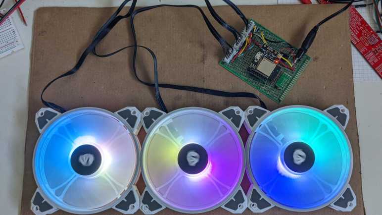
After proving my fan blade LED strobe idea worked with a minimalist Arduino sketch, I ported that code over as an ESPHome custom component. I thought it would be good practice for writing ESPHome custom components and gain Home Assistant benefit of adding adjustments in software. For me it was easier to create an analog control with a few lines of YAML and C, than it would be to wire up a potentiometer. (I recognize it may be the reverse for people more comfortable with hardware than software.)

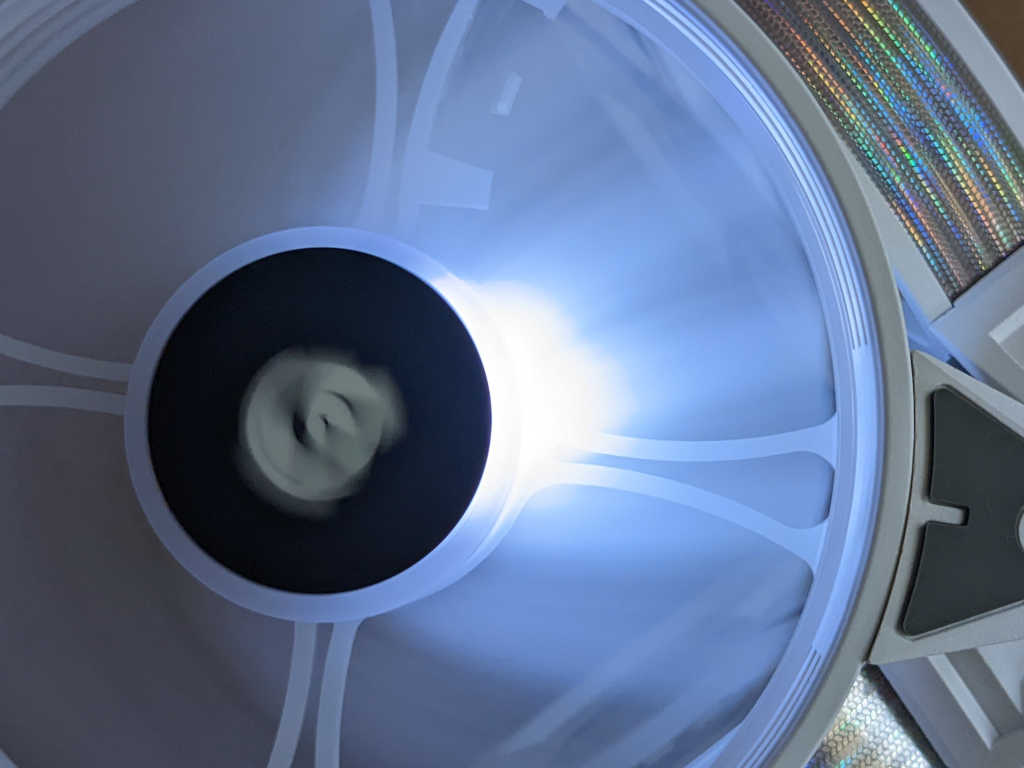
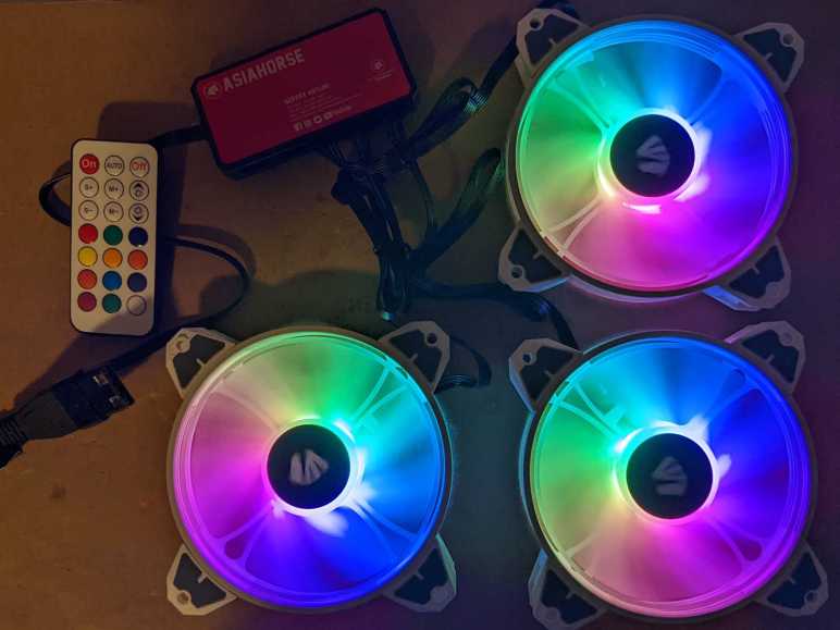
The first adjustment “Fan Speed Control” actually did not require custom component at all: making the fan speed adjustable utilized the built-in fan speed component. In my minimalist sketch the fan is always running at full speed, now I can adjust fan speed and verify that the strobe logic indeed stays in sync with the fan speed. Meaning the strobe keeps these fan blades visually frozen in the same place regardless of their rotational speed.

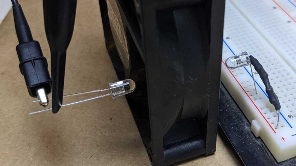
The first custom output component adjustment “Strobe Duration” changes the duration of LED strobe pulse, from zero to 1000 microseconds. For this LED array, I found values under 100 to be too dim to be useful. The dimmest usable value is around 100, and things seem to work well up to 300. I start detecting motion blur above 300, and things are pretty smeared out above 600.

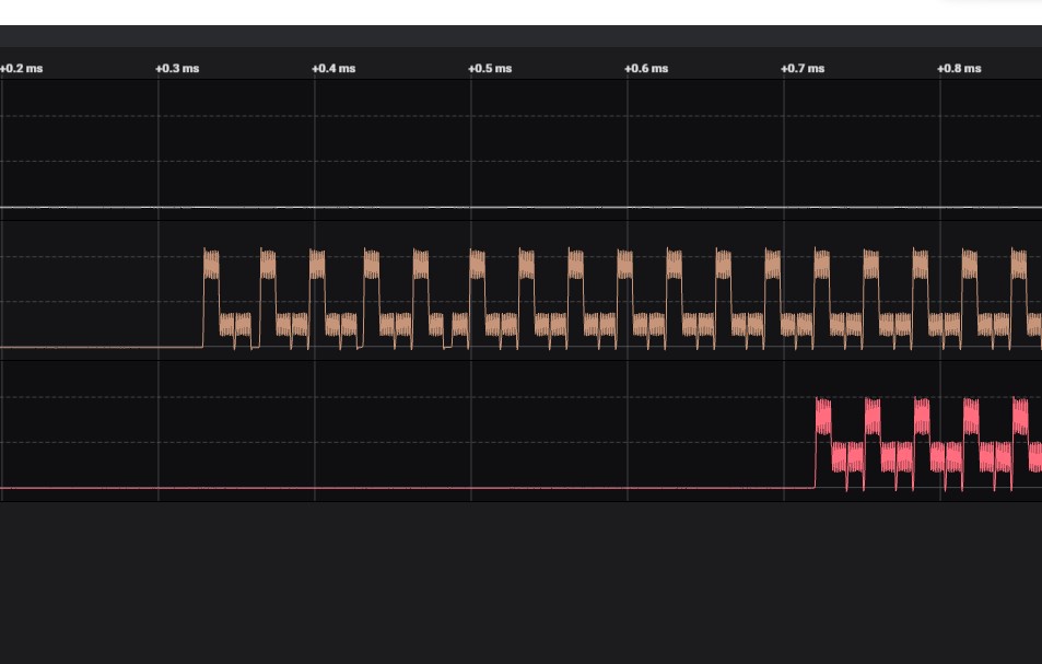
The next addition is a toggle switch “Strobe Tachometer Toggle”. Because the tachometer signal pulses twice per revolution, I ignore every other pulse. But that means a 50% chance the code will choose to trigger on the wrong pulse, resulting in a visually upside-down image. When this happens, this toggle allows us to flip to trigger on the opposing pulse, flipping the frozen visual right-side up.

The final custom component adjustment “Strobe Delay” adds a delay between triggered by tachometer wire and illumination of LED strobe. This changes the point at which the fan is visually frozen by the strobe light. Dynamically adjusting this value makes it look like the fan blade is slowly rotating position even though it is actually rotating at ~1200RPM. I think it is a fun effect, but to fully take advantage of that effect I will need longer delays, which means finding how I could move that work outside of my interrupt service routine. Inside the ISR I should set up a hardware timer for this delay and turn on LED when timer expires. I can then use the same mechanism to set a timer for LED duration and turn off LED when that timer expires.

Unfortunately, there are only two hardware timers on an ESP8266, and they are both spoken for. One runs WiFi, the other runs Arduino core for things like millis(). To explore this idea further, I will need to move up to an ESP32 which has additional hardware timers exposed to its Arduino core. And if I choose to explore that path, I don’t even need to redo my circuit board: there exists a (mostly) drop-in ESP32 upgrade for anything that runs a Wemos D1 Mini.


YAML Excerpt:

esphome:
  includes:
    - led_strobe_component.h

output:
  - platform: esp8266_pwm
    pin: 14
    id: fan_pwm_output
    frequency: 1000 Hz
  - platform: custom
    type: float
    lambda: |-
      auto led_strobe = new LEDStrobeComponent();
      App.register_component(led_strobe);
      return {led_strobe};
    outputs:
      id: strobe_duration_output
  - platform: custom
    type: float
    lambda: |-
      auto led_strobe_delay = new LEDStrobeDelayComponent();
      App.register_component(led_strobe_delay);
      return {led_strobe_delay};
    outputs:
      id: strobe_delay_output

fan:
  - platform: speed
    output: fan_pwm_output
    id: fan_speed
    name: "Fan Speed Control"

light:
  - platform: monochromatic
    output: strobe_duration_output
    id: strobe_duration
    name: "Strobe Duration"
    gamma_correct: 1.0
  - platform: monochromatic
    output: strobe_delay_output
    id: strobe_delay
    name: "Strobe Delay"
    gamma_correct: 1.0

switch:
  - platform: custom
    lambda: |-
      auto even_odd_flip = new LEDStrobeEvenOddComponent();
      App.register_component(even_odd_flip);
      return {even_odd_flip};
    switches:
      name: "Strobe Tachometer Toggle"

ESPHome custom component file led_strobe_component.h:

#include "esphome.h"

volatile int evenOdd;
volatile int strobeDuration;
volatile int strobeDelay;

IRAM_ATTR void tach_pulse_handler() {
  if (0 == evenOdd) {
    evenOdd = 1;
  } else {
    delayMicroseconds(strobeDelay);
    digitalWrite(13, HIGH);
    delayMicroseconds(strobeDuration);
    digitalWrite(13, LOW);
    evenOdd = 0;
  }
}

class LEDStrobeComponent : public Component, public FloatOutput {
  public:
    void setup() override {
      // LED power transistor starts OFF, which is LOW
      pinMode(13, OUTPUT);
      digitalWrite(13, LOW);

      // Attach interrupt to tachometer wire
      pinMode(12, INPUT_PULLUP);
      evenOdd = 0;
      attachInterrupt(digitalPinToInterrupt(12), tach_pulse_handler, RISING);

      strobeDuration = 200;
    }

    void loop() override {
    }

    void write_state(float state) override {
      // Multiply by 1000 = strobe duration from 0 to 1ms.
      strobeDuration = 1000 * state;
    }
};

class LEDStrobeEvenOddComponent: public Component, public Switch {
  public:
    void write_state(bool state) override {
      evenOdd = !evenOdd;
      publish_state(state);
    }
};

class LEDStrobeDelayComponent: public Component, public FloatOutput {
  public:
    void write_state(float state) override {
      strobeDelay = 1000*state;
    }
};

LED Strobing to Fan Speed Signal

The reason I cared about power-on response time of a salvaged LED array is because I wanted to use it as a strobe light shining on a cooling fan pulsing once per revolution. Historically strobe lights used xenon bulbs for their fast response, as normal incandescent bulbs were too slow. This LED array used to be a battery-powered work light with no concern of reaction time, but LEDs are naturally faster than incandescent. Is it fast enough for the job? PC case fan specifications usually range from the hundreds to low thousands of RPM. Using 1200RPM as a convenient example, that means 1200/60 seconds per minute = 20 revolutions per second. Pulsing at 20Hz should be easy for any LED.

For the hardware side of controlling LED flashes, I used a 2N2222A transistor because I had a bulk bag of them. They are usually good for switching up to 0.8 Amps of current. I measured this LED array and it drew roughly 0.3 Amps at 11.3V, comfortably within limits. I just need to connect this transistor’s base to a microcontroller to toggle this light on and off. For this experiment I repurposed the board I had built for the first version of my bedstand fan project. I unsoldered the TMP36 sensor to free up space for 2N2222A and associated LED power wire connector.

This board also had the convenience of an already-connected fan tachometer wire. My earlier project used it for its original purpose of counting fan RPM, but now I will use those pulses to trigger a LED flash. Since timing is critical, I can’t just poll that signal wire and need a hardware interrupt instead. Within Arduino framework I could use attachInterrupt() for this purpose and run a small bit of code on every tachometer wire signal pulse. Using an ESP8266 for this job had an upside and a downside. The upside is that interrupts could be attached to any available GPIO pin, I’m not limited to specific pins like I would have been with an ATmega328P. The downside is that I have to use an architecture-specific keyword IRAM_ATTR to ensure this code lives in the correct part of memory, something not necessary for an ATmega328P.

Because it runs in a timing-critical state, ISR code is restricted in what it can call. ISR should do just what they absolutely need to do at that time, and exit allowing normal code to resume. So many time-related things like millis() and delay() won’t work as they normally would. Fortunately delayMicroseconds() can be used to control duration of each LED pulse, even though I’m not supposed to dawdle inside an ISR. Just for experiment’s sake, though, I’ll pause things just a bit. My understanding of documentation is as long as I keep the delay well under 1 millisecond (1000 microseconds) nothing else should be overly starved for CPU time. Which was enough for this quick experiment, because I started noticing motion blur if I keep the LED illuminated for more than ~750 microseconds. The ideal tradeoff between “too dim” and “motion blurred” seems to be around 250 microseconds for me. This tradeoff will be different for every different combination of fan, circuit, LED, and ambient light.

My minimalist Arduino sketch for this experiment (using delayMicroseconds() against best practices) is publicly available on GitHub, as fan_tach_led within my ESP8266Tests repository. Next step in this project is to move it over to ESPHome for bells and whistles.

NEXTEC Work Light LED Array

While experimenting with 5V power delivery over USB-C, I thought of an experiment that will utilize my new understanding of computer cooling fan tachometer wire. For this experiment I will need a light source in addition to the fan itself. I wanted a nice and bright array of many LEDs, and preferably something already set up to run at around 12V so I wouldn’t have to add current-limiting resistors. A few years ago, I took apart a Sears Craftsman NEXTEC work light for its battery compartment. Now it is the LEDs turn to shine. That battery pack used three lithium 18650 cells in series, so it is in the right voltage range.

I think there was only a single fastener involved in this LED array, and it was already gone from teardown earlier so now everything slid apart easily.

I like the LED housing and intend to use it, but I wanted to take a closer look at the LED array.

I confirm the 24 white LEDs visible before disassembly, and there’s nothing else hiding on this side of the board, just the power supply wires looping through for a bit of strain relief. We can also see that Chervon Group was the subcontractor who produced this device to be sold by Sears under their Craftsman branding.

Everything is on the backside of this circuit board. From here we can see the 24 LEDs are arranged in 12 parallel sets of 2 LEDs in series, each set with a 240 Ohm resistor between them. Beyond that, to lower left I see a cluster of components and I’m not sure what they do. My best guess is battery over-discharge protection. Perhaps the component marked ZD1 is a Zener diode to detect voltage threshold, working with power transistor Q1 to cut power if battery voltage drops too low.

The most important thing is that I don’t see a microcontroller that requires time to boot up. I will be pulsing this LED array rapidly and want minimal delay between power and illumination. If delay proves to be a problem, I’ll try bypassing those lower-left bits: Relocate the power supply wire (brown wire, connects between markings R1 and ZD1) so it connects directly to the LED supply plane. Either to the transistor tab adjacent to the Q1 marking, or directly to the high end of any of those 12 parallel LED strings. But I might not need to perform that bypass. I will try my experiment with this circuit board as-is.

Fan Blade Counter Success: Infrared LED Photovoltaic Effect

I wanted to rig up a fan blade counter as an oscilloscope exercise: set up an emitter and hook the receiver up to the oscilloscope and count the spinning blades via interruption between emitter and receiver. I had a box of consumer infrared remote-control emitter and receivers, but those receivers were too smart and sophisticated for my project. I needed something simpler.

Looking at what I (literally) have on hand, I wondered if the oscilloscope is sensitive enough to pick up a photovoltaic effect on these IR emitters. I remembered that every piece of silicon responds to light to some degree. This fact caused problems like the first run of Raspberry Pi 2 that resets when exposed to bright light, which is why they’re usually shrouded in black plastic to block light. I already had an IR emitter set up to pulse at 38kHz, so I placed another emitter pointed face-to-face wired directly to an oscilloscope probe: the probe connected to LED anode and corresponding ground pin connected to LED cathode.

The answer is: yes, the oscilloscope can pick up electrical activity on the IR emitter diode as it was stimulated by an identical IR emitter. It’s not a very clean square wave, with a sharp climb and a slower decay, but it’s clearly transmitting the 38kHz signal. I don’t know how to build a circuit that triggers behavior based on such small voltages, but right now I don’t have to. The exercise is measuring fan blades and see how it correlates to fan tachometer signal on a multichannel oscilloscope, and I have an effect strong enough to be picked up by said oscilloscope.

The emitter LED was removed from the 38kHz circuit. Now it lives on the breadboard power rail, so it is always on. The other emitter LED (acting as receiver) was placed on the other side of the fan. A separate set of oscilloscope probes were connected to the fan tachometer wire. I gave the fan power, and saw the graph I had hoped to get:

The yellow square wave is the fan tachometer signal, and the rougher purple wave is the receiving LED. There are seven blades on this particular fan, so seven purple cycles would correspond to one revolution of the fan. I count seven purple cycles for every two yellow cycles, finally confirming that the cooling fan tachometer signal goes through two full cycles on every fan revolution.

Fundraising Keychain LED Flashlight

Sometimes an organization will send a little gift in the mail accompanying a plea for donation. These small tokens are sent as a psychological tactic to generate a return that far outweigh their low cost. I’ve received things like address stickers, notepads, and the occasional calendar. And now, I can add “keychain LED flashlight” to the list.

This item was included in a request to donate to Doctors without Borders, a well-respected organization well worth donating more money to. Whether they sent me a keychain flashlight or not. But it is on the teardown bench because I’m curious about the implementation details of a freebie giveaway that must have been designed for the lowest possible cost.

A power switch slider illuminates the commodity 5mm white LED. Judging by the exterior, I expect to find a LED and a coin cell battery inside, based on the width probably a CR2032 or CR2035. The power switch would have been designed to open/close the circuit with minimal parts. I see a seam on the side of the device, so the silvery plastic body must consist of at least two pieces. The switch would be the third silvery plastic piece. White plastic on top and bottom may be two pieces or a single piece. So not counting the keychain itself, I expected five pieces of plastic plus the LED and coin cell for seven parts.

My expectations were proven wrong as soon as I removed the first piece. White pieces top and bottom were indeed separate pieces, held together in a friction fit. A good friction fit requires tight tolerances which costs money. I had expected cheaper loose tolerances which would have meant holding things together with glue, but this wasn’t glued together.

Once I removed top and bottom white plastic pieces, rest of the flashlight was easily disassembled. Power comes from a trio of tiny LR621 coin cell batteries, not the single CR2035 I expected. As a result, there was more empty space inside than I had expected including an empty rear cavity that is big enough to hide a microSD card or three. The power switch was indeed a clever mechanism, but it required an extra piece of metal that I thought it might have done without.

This little LED flashlight was indeed an extremely simple and low-cost device, just not quite as simple or low cost as I had thought it would be. Nice to see my assumptions proven wrong.

Bedside Fan and Light V2

I took apart the Asiahorse Magic-i 120 V2 control hub and remote because I didn’t need them anymore: I could control its trio of fans with my own circuit board. How shall I wield such power? It was fun playing with 3D coordinate mapping with a Pixelblaze, but my most immediate need is a lot less exciting: combination bedside fan and light to replace my first bedside fan project. (Which didn’t have a light.)

For such a simple use, the power of a Pixelblaze is overkill. So, my board was modified to use an ESP8266 (Wemos D1 Mini module) as its brain, running ESPHome for integration with Home Assistant. In the Pixelblaze demo, the fans were always on. Now they will be controlled by that ESP8266 as well.

I’m still not settled enough on the idea to spend the time designing and 3D printing a proper frame, but at least I’ve put a bit more effort into this cardboard creation. I’m reusing a corner of a Newegg shipping box (I think it was the very box used to ship the Asiahorse fan bundle) and I’ve turned it inside out so at least I don’t have to stare at the Newegg logo every time I’m in bed.

Three large holes, one per fan, was cut from that cardboard for airflow. Twelve more holes, four per fan, were drilled into the cardboard for fan mounting screws. The physical assembly came together quickly, but there were a few more hiccups.

First problem was that FastLED, the addressable LED Arduino library used by ESPHome, is not compatible with the latest Arduino 3 framework at the time of this writing. Relevant ESPHome documentation page listed the issues as 1264 and 1322 filed against FastLED Github repository. Until they are resolved, ESPHome offers a workaround for compiling against Arduino framework 2.7.4. Which is what I did to run these WS2812 LEDs. For the first draft, I’m not going to use the addressable nature at all, just a single solid color. I think it would be cool to have a falling waterfall pattern on these lights, but that’ll be experimentation for later.

The second problem is that PWM control of fan speed results in an audible whine, probably an 1kHz whine which is the practical maximum speed for ESP8266 software PWM. The previous fan project removed the audible whine by adding a capacitor to smooth out voltage output. I could do that again, one capacitor per fan, but these fans run quietly enough at full speed I’m willing to skip PWM and have just on/off control.

The final problem is that I still want this fan to be responsive to temperature changes, turn itself off in the middle of the night when it got cool enough. I wasn’t happy with the TMP36 sensor I bought for the previous experiment, so now I’m going to try another sensor: the DS18B20.

RGB LED Fan Hub and Remote (Asiahorse Magic-i 120 V2)

I bought the Asiahorse Magic-i 120 V2 package from Newegg, which bundled three 120mm fans with embedded RGB LEDs with a hub and a remote to control those LEDs. Now that I have successfully created a control circuit for my own independent control of those fans and their LEDs, I no longer have any use for the hub and remote.

The remote has an array of 21 membrane buttons. Across the top, we can turn the LEDs “On” and “Off”. “Auto” will start running an animated pattern. Just below the “Off” button are brightness controls. S+ / S- controls the speed for animations, and M+ / M – cycles through different animated patterns. Bottom 12 buttons will show the selected solid color.

Top membrane is held on with moderately strong adhesive that could be peeled off, exposing the less interesting side of its circuit board.

Flipping the board over showed a single chip with its support components. There were no visible markings on the chip. Battery contact springs are at the bottom, the top features an infrared remote control LED emitter, and a few passive components in between.

After disassembling the remote, I started on the hub.

There were no exposed fasteners top or bottom. I pushed on the bottom sticker and felt the corners move.

The bottom sticker is glued on more tenaciously than the remote membrane keyboard and refused to come off cleanly. But at least those four Philips head fasteners are now exposed.

Not much to see on the bottom.

Flipping the circuit board over exposed… not many more chips than the remote. Most of the surface area are consumed by connectors all around the perimeter, and traces to connect them.

I’m glad to see fan connector pin labels are consistent with my reverse-engineered pinout table. A large component on this board appears to be a power transistor. I probed its pins and one of them is connected to all “F-” pins, so it is present for fan control. There are three sets of unused pads across the middle, provision for WS2812 LEDs wired in parallel with the fans. These three are chained together, left-to-right, with the leftmost LED receiving the same “DI” (data input) as all fans. When present, these three LEDs would act identically to first 3 out of 12 LEDs on board each fan.

There were a few other unpopulated pads on this circuit board, but there is one part I found fascinating for its absence: an infrared receiver like the one I found in a Roku. I don’t see one, and I don’t see solder pad provision for one. How could the hub receive IR remote signals without one? I know the remote and hub works together, so does this mean they communicate by radio frequency instead of infrared? I don’t know enough about RF circuits to look for components that would implement such a thing. I had thought all RF devices sold in the United States are required to have an FCC ID printed on it, but none are visible. Perhaps certain unlicensed frequency bands are exempt from FCC ID requirement? Shrug, doesn’t matter to me anymore as I won’t be needing this remote or hub to put their associated fans to use.

Orthogonal Fans with Pixelblaze 3D Mapping

I have built a control board for a trio of affordable PC case fans, replacing their bundled control hub of this Asiahorse Magic-i 120 V2 system. With my board I can control individual RGB LED inside these fans with help of a Pixelblaze LED controller. My initial tests used simple built-in linear patterns, but I wanted to use patterns that take advantage of 3D coordinate mapping. This is my favorite part of Pixelblaze and a core part of my Glow Flow project.

To get a 3D structure out of three fans, I did the easiest and most expedient thing: orient them orthogonal to each other with a few twist-ties. Now every fan motor axis lines up with one of three axes in 3D space. I have a Pixelblaze 3D coordinate test program already in hand, the RGB-XYZ 3D Sweep program I created during Glow Flow. All I had to do was create a 3D coordinate map in my Pixelblaze to describe LED layout in three-dimensional space.

I opened up the Pixelblaze mapping editor and… immediately got stuck. Where, exactly, should I map these LEDs? Physically, they are surface mounted on the central hub. However, their light diffused by translucent fan blade plastic, no longer fixed to a single location but distributed across entire fan diameter. Should I map the LEDs where they are physically? Or fan blade outer perimeter? Or somewhere in between? There really isn’t one single location for resulting output of a single LED.

I decided to experiment by writing my mapping code so a single variable controls how far from the center each location is. When pixelRadius is zero, everything is at the center and not very interesting. When set to 0.5, everything is mapped to the perimeter. I adjusted this value until the pattern “looked right” and that ended up at 0.4. I’m not satisfied with the empirical nature of this value, but I haven’t figured out a better way to account for diffusion.

Another problem with these LEDs is that they weren’t placed with precise coordinates in mind. I think LEDs were laid out on the circuit board relative to wiring bundle location, which is slightly offset from one of the four mounting arms. As a result, the LEDs aren’t aligned to any reference point on the exterior. To use an analog clock face as example, these LEDs are evenly placed but slightly offset from the hour numbers. Instead of lined up at 12, 1, 2, 3. They are at 12:10, 1:10, 2:10, etc.

These fans are physically squares with side lengths of 120mm. They can be installed in one of four orientations that are 90 degrees from each other and be mechanically fine. I usually choose my orientation based on whichever makes the wiring most convenient. But whatever the motivation, my 3D coordinate map would have to compensate for the resulting rotation.

The answer for both of the above rotation compensation concerns is an array fanRotationCorrection. One value for each fan, a sum of physical and LED offset rotations (in radians) added into coordinate map angle calculation for that fan.

Here is the result of my 3D pixel map running my RGB-XYZ sweep test program:

Here is my Pixelblaze Pixel Mapper code. [UPDATE: I later noticed that I got my Z-axis backwards. Be aware that both the video embedded in the tweet and this pixel mapper code are known to be flawed. At least they’re consistent with each other!]

function(pixelCount) {
  pixelPerFan = 12;
  pixelRadius = 0.4;
  fanRotationCorrection = [0.65, 0.65, 0.65];

  var map = [];
  for (i = 0; i < pixelCount; i++) {
    var ledNumber = i % pixelPerFan;
    var ledRadians = ((ledNumber/pixelPerFan) * Math.PI * 2);

    if (i < pixelPerFan) {
      ledRadians += Math.PI*fanRotationCorrection[0]
      map.push([0, 0.5 + Math.cos(ledRadians)*pixelRadius, 0.5 - Math.sin(ledRadians)*pixelRadius]);
    } else if (i < pixelPerFan*2) {
      ledRadians += Math.PI*fanRotationCorrection[1]
      map.push([0.5 - Math.cos(ledRadians)*pixelRadius, 0, 0.5 - Math.sin(ledRadians)*pixelRadius]);
    } else if (i < pixelPerFan*3) {
      ledRadians += Math.PI*fanRotationCorrection[2]
      map.push([0.5 - Math.cos(ledRadians)*pixelRadius, 0.5 + Math.sin(ledRadians)*pixelRadius, 0]);
    } else {
      // Unexpected pixels are placed at origin
      map.push(0,0,0);
    }
  }
  return map;
}

My Asiahorse investigation results were also posted to Pixelblaze forums. And now that I have full and complete control over these fans, I no longer need the hub that came in the box.

Control Board for Asiahorse 120mm Fans with RGB LED

I have a trio of PC cooling fans with embedded addressable RGB LED. They were designed to plug into a control hub that came in the bundle, but that hub had only a limited set of patterns and appeared to send the same signal to all fans. In order to run my own light show and control each fan individually, I determined the fan pinout and will now build my own control board for these fans.

The first problem was wiring. These fans came with a JST-PH style plug with 2.0mm pitch. (Distance between pins.) My perforated prototype circuit boards (and most connectors and components on hand) have a pitch of 0.1″ (~2.54mm) and would not fit. To work around this problem today, I cut off the factory connector and crimped on a replacement. These are JST-XH clones(*) with 0.1″ pitch. In the future, I might consider buying some perforated prototype boards with 2.0mm pitch (*) but that would have the problem of using components with 0.1″ pitch. The real solution is to make my own circuit boards that can accommodate whatever pitch I need, but that’s beyond my reach at the moment.

To generate individual control signals for these fans, I will be using the very awesome Pixelblaze controller. For power I will be using one of my salvaged 12V DC power bricks. It is rated for up to 1.5A which should be sufficient for a trio of fans and 12*3 = 36 LEDs. The barrel jack has a 5.5mm outer diameter and 2.1mm inner diameter, so I soldered a matching power jack (*) to the board. This will deliver power for the fans, with a decoupling capacitor to smooth things out. A buck converter (*) with convenient 5V preset feeds from that 12V rail to deliver 5V for Pixelblaze and LEDs.

I soldered some 2N2222A transistors for potential control of fan speed, but for this first iteration they’re pulled high so the fans spin all the time. It would have been easier to solder fan motor low wire directly to ground, but I have ambition of fan control in a future update.

The LEDs are connected in serial across all three fans. Pixelblaze data is connected to “data in” of the first fan, whose “data out” is connected to “data in” of the second fan, and onwards to the third fan. Configured for 12*3 = 36 WS2812-style LEDs, the Pixelblaze has individual control of every LED with a single data line. And for the first time, these three fans show patterns different from each other. With this new power I can make things even more interesting.


(*) Disclosure: As an Amazon Associate I earn from qualifying purchases.

Pinout for Asiahorse 120mm Fan (Magic-i 120 V2)

The Asiahorse Magic-i 120 V2 bundle included three 120mm cooling fans with integrated addressable RGB LEDs. These fans have a six-wire connector designed to be plugged into a hub that was included in the bundle, along with a remote control to change the light shown performed by those LEDs. Most users just need to plug those fans into the included hub, but some users like myself want to bypass the hub and control each fan directly. For this audience, I present the fan connector pinout derived from an exploratory session on my electronics workbench.

Since this was reverse engineered without original design documents, I don’t know which side is considered “pin #1” by the engineers who designed this system. These connectors appear to be JST-PH, whose datasheet does point to one side as “Circuit #1”. But there’s no guarantee the engineers followed JST convention. To avoid potential confusion, I’ll call them only by name.

NameSystemComments
+12VFanHigh side of fan motor. Hub connects this wire directly to +12V power input.
Motor LowFanLow side of fan motor. Use a power transistor between this wire and ground to control fan speed.
GroundFan + LEDPower return for LED circuit and can be used for fan motor low side as well. Hub connects this wire directly to power input ground.
Data InLEDInput control signal for addressable RGB LED. Compatible with WS2812/”NeoPixel” protocol.
+5VLEDPower for LED circuit. Hub connects this wire directly to +5V power input.
Data OutLEDControl signal for addressable RGB LED beyond the end of LED string inside the fan. Useful for chaining multiple units together by connecting this wire to Data In of the next device in line.

Now that I understand its pinout, I will build my own control circuit to replace the default Asiahorse hub.

Exploring 6-Wire Connector of Asiahorse Magic-i 120 V2

I was curious about PC accessories with embedded addressable RGB LED, so I bought the cheapest item available on Newegg that day. I have verified it works as originally intended, and now I’m going to dig deeper. This Asiahorse Magic-i 120 V2 is a three-pack of 120mm fans with integrated LEDs. All three fans plug into a hub that has a corresponding remote control for me to select from a list of programmed patterns. This bundle is fine if I’m satisfied with those patterns, but I want display patterns of my own.

Each fan connects to the hub through this six-wire connector. The distance between each pin is 2mm. Judging by the pitch and physical appearance, I guess they are JST-PH or a clone. (I don’t have any 6-conductor JST-PH to verify.) This is mildly inconvenient because my workbench is setup to work with 0.1″ pitch (~2.54mm) connectors so it’s not very easy for me to probe those signals as-is.

The solution is a quick soldering project to give me an exploration board. I cut the bundle of six wires and inserted a small piece of perforated prototype board. Each of the six wires are then bridged with an exposed length of solid wire, easy for me to clip probes onto.

Trying the easy thing first, I probed for continuity between these six wires and the power input wires. This gave me location for +12V source, +5V source, and ground. Armed with this information, I soldered capacitors to smooth out both power rails, because the AC adapter I’m using is designed for far higher wattage than a few LEDs and it’s not unusual for switching power supplies to be noisy at low power levels. (And the cheap ones are always noisy at all power levels…)

With three out of six wires identified for power, this left me with three more wires to decipher. Here are my candidates:

  • Fan control: it may be one (or none) of the following:
    • Fan motor high side: the fan may be internally connected to the ground wire, and the high side wire is left exposed here for external PWM or on/off control with a power transistor.
    • Fan motor low side: the same idea but reverse: fan motor is internally connected to +12V and the low side is exposed here for external PWM or on/off control with a power transistor.
    • Fan motor PWM: Neither of the above. Instead of leaving either high or low side unconnected for external power transistor, a suitable power transistor is built into the fan and controlled with a 25kHz PWM signal as used in 4-wire fans.
  • Fan tachometer like the type I found in 3-wire fans.
  • LED Data In: addressable RGB signal input.
  • LED Data Out: signal that has passed through the LED string inside this device and ready to be passed on to other LEDs in other devices down the chain.

To decipher which wires are which of those candidate capabilities, I connected my Saleae Logic 8 to the three unknown wires. I started an analog waveform capture session and used the fan remote control to command that all fans show a solid green.

The top line in white stayed at 0V through the entire session. This may be the tachometer wire, or it may be fan motor low side. To determine which, I disconnected everything other than the +12V and ground wires. The fan did not move. I connected the wire corresponding to this white line to ground, and the fan started spinning. Conclusion: this wire is fan motor low side.

The middle line in brown shows a distinct repeating pattern. The bottom line in red shows the same repeating pattern, but delayed by 12 cycles. Since there are 12 LEDs in a fan, that means the middle brown line is LED Data In and the red line is LED Data Out.

To verify LED Data In, I connected +5V, ground, plus this wire to the data pin of a Pixelblaze. After I configured the Pixelblaze to emit control signal for a string of 12 x WS2812 (NeoPixel) LEDs, I saw them light up appropriately on the fan.

To verify LED Data Out, I connected it to the data input pin of an array of 64 WS2812 LEDs. I configured the Pixelblaze for 12 + 64 = 76 pixels. After colorful pixels cycle through the fan, they marched onwards to the array as appropriate for LED Data Out.

With these functions verified, I’m confident enough to describe this Asiahorse fan pinout.

Asiahorse Magic-i 120 V2

I wanted to play with a set of PC case cooling fans with embedded addressable RGB LEDs, with the intent of learning how to control them for a future project. For extra challenge, I got a multipack that combined both fan and LED controls into a single (probably proprietary) connector that plugged into a bundled hub. Using the selection criteria of “Lowest bidder of the day” I bought a three-pack of fans: the Asiahorse Magic-i 120 V2 and I look forward to seeing how it works.

Before I start cutting things up, I need to verify the product worked as originally designed. I won’t need a computer for this as this multipack came with a remote control for the hub that allows operation without a computer. This lets me explore its signals without the risk of damaging a computer. I just need to supply power in the 4-pin accessory format popular with pre-SATA hard drives and optical disks. I didn’t need a computer here, either, as I had an AC adapter with this plug that originally came in a kit that turned internal HDDs into USB HDDs.

There were no instructions in the box, but things were straightforward. Three fans plugged into the hub, and a power cable connected my AC adapter to the hub. As soon as I turned on the power, all three fans started spinning. The LED light show didn’t start until I pressed the “On” button on the remote.

RGB LEDs in this fan are mounted in the hub, on the outside perimeter of the motor control board. I count 12 LEDs and they aimed along motor axis upwards into the center portion of translucent fan blades. These colorful lights are then diffused along length of the blade, resulting in a colorful spinning disk. While shopping on Newegg I saw other arrangements. Some fans have LEDs around the outside perimeter instead, and some fans illuminate both the hub and the perimeter. Each manufacturer hoping to capture the attention of a buyer with novelty of their aesthetic.

This remote control allowed me to cycle between various colorful programs or choose from a set of solid colors. I had hoped the colorful programs would ripple across the fans, but all three fans appear to display identical light sequence. I could control LED brightness or turn all the lights off, but I didn’t seem to have any control over fan speed. I guess this is where an instruction manual would have been useful.

If I wanted to build something bright and colorful that circulates air, almost everything is already here and ready to go. I just have to wire up a power switch to turn everything on/off, and the remote can take care of the rest. But I didn’t buy this just to have some lights. I wanted full control and I’m not afraid to start cutting things up to get there.

Shopping for PC Cooling Fans with RGB LED

I’ve decided to investigate controlling the RGB LEDs embedded in aesthetics-based PC accessories. I’m not interested in using them for my PC, but as research for a yet to be determined future electronics project. I wanted something that is a standardized commodity with a large range of variety in the ecosystem and have some usefulness beyond just looking shiny. I settled on 120mm PC cooling fans.

There are many common sizes for cooling fans, but I’ve found 120mm to be the most common for aftermarket cooling. They’re larger than average for CPU cooling, but not too large especially for heat-pipe based cooling towers. But they’re typically installed for general cooling in tower cases, whose cooling vents are cut for 120mm fans. Covering both popular use cases mean more options.

Looking around on my NewEgg, I find that fans sold individually typically have two separate connectors. One for LED and one for fan control. To the rest of the computer, these fans look like two separate peripherals: the LED and the fan. They just happened to coexist in the same device. The fan control connector sometimes just have two wires for +12V and ground. Some have a third tachometer wire for reporting speed, and some have a fourth wire for built-in PWM control. Here’s an example of a CPU cooler the Vetroo V5 whose fan has two connectors: a 4-pin CPU cooler fan control connector and a JRAINBOW RGB LED plug. These should be simple and straightforward to interface.

More challenging are fans that use an intermediate hub. The hub has a connector for power and for JRAINBOW, consolidating those signals into a proprietary connector. I started contemplating this particular Rosewill RGBF-S12001 three-pack of fans which use such a design. I think I can decipher roles of each wire so I could bypass the hub and control each fan directly. This multipack also had a remote control for direct control of the hub without a computer. This is appealing to me, because independent control meant I didn’t need a PC involved as I probed how it worked. If I should make a fatal mistake (say, accidentally short-circuited something) it should only kill the hub or the fan and not an entire computer.

As I scrolled down, though, Newegg showed me several other items under “similar products”. I saw an even more discounted three-pack of fans: the Asiahorse Magic-i 120 V2. Three fans for fourteen bucks, well within my impulse buy range. I’ll buy the pack and see what it does.

Repurposing PC RGB LED Accessories

I’m quite comfortable poking around inside the tower case of a DIY PC. I’ve built a few PCs from components, and I’ve bought a few that came prebuilt by a shop. In my PC experience I’ve focused on the functional side of things and haven’t paid much attention to the aesthetics side. There’s a whole segment of the market enchanted with flashy LEDs. As an electronics hobbyist, it had been hard for me to look at those accessories seriously. I know how little addressable RGB LED modules cost in bulk, and it is quite clear those PC accessories were sold at a huge profit margin. I would be more inclined to build my own LED creations like Glow Flow than to pay a premium just for overpriced flashy lights in my PC.

But what if I looked beyond products’ MSRP? Since this particular market is about novelty, just like the clothing fashion industry there is a high turnover of products. The huge profit margin entices startups hoping to make it big, and most don’t. High product turnover means there are those who upgrade to the latest look. Each of these scenarios can lead to products sold well below MSRP: (1) clearance sales on unsold inventory of “old looks” (2) liquidation sales from bankrupt companies, and (3) secondhand markets (eBay/Craigslist) for those who have upgraded. A bargain hunter can find LED-bedazzled gear well below the price of new equipment, and in extreme cases even lower than price of buying new WS2812 modules directly.

Well, now I’m interested! Not for my PC, but for potential future electronics projects. Which means looking at these products and try to figure out how I can repurpose them. I started by looking at the product pages for a few PC hardware component companies and their advertising spiel for RGB LED accessories.

  • Corsair uses the iCUE branding as an umbrella covering aesthetics-based accessories. Some are the addressable LEDs I care about, but not all of them.
  • Gigabyte uses the name RGB Fusion.
  • Asus calls theirs Aura.
  • MSI calls theirs Mystic Light.

I hit a gold mine on MSI’s Mystic Light site, because their FAQ included an entry “What is Mystic Light Extension” that gave the following description:

Mystic Light Extension is a feature of Mystic Light software which allows user to control colors and effects of partner’s product such as RGB LED Strips, RGB PC Fans or RGB PC Case via on-board JRGB / JRainbow / JCorsair pin header.

    JRGB (4-Pin / PIN-definition: 12V/G/R/B): The JRGB pin header provides up to 3A (12V) power supply for non-addressable 5050 RGB LED solution showing single color.
    JRAINBOW (3-Pin / PIN-definition: 5V/D/-/G): The JRainbow pin header provides up to 3A (5V) power supply for addressable WS2812 RGB LED (ARGB) solution showing rainbow color.
    JCORSAIR (3-Pin / PIN-definition: 5V/D/G): The JCorsair pin header provides up to 3A (5V) power supply to Mystic Light software compatible CORSAIR devices.

This tells me products that use the JRGB header are colorful but not individually addressable. Products using JRAINBOW or JCORSAIR are 5V devices that uses a single data pin and no clock. This is a very strong hint these products are made of LEDs made of either WS2812 (“NeoPixel”) or alternatives that understand the same control signals. I will go look for a bargain and try one out.