KISS Tindies: Ace/Spaceman II

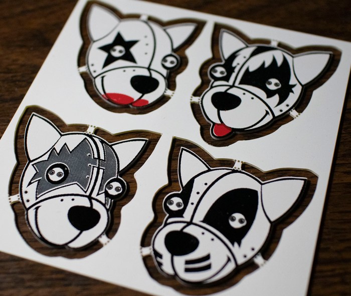
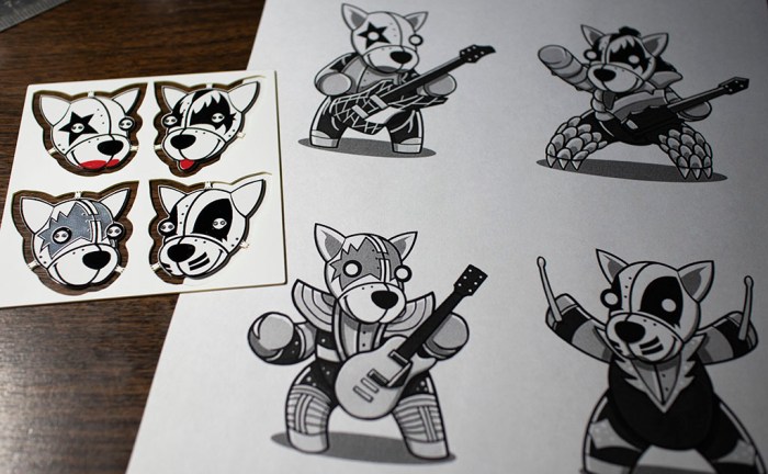
One of the scramble before Sparklecon was getting my KISS band back together. On the weekend prior to Sparklecon, the band went on tour in their first public appearance. The good news: they were very well received and people loved them! The bad news: Someone loved them so much they decided to adopt my Spaceman, taking him home without my permission. I was missing a member of the band.

I had already signed up to talk about the band for Sparklecon, and it would be a bit lame not to have the full band at my talk. This means making Spaceman II, but for that I would need another KISS Tindie PCB. Fortunately, Emily came to the rescue! She was also at Superconference and had also picked up a KISS Tindie PCB of her own. She generously donated her panel so I could rebuild my blinky band.

Emily KISS Tindie Panel.jpg

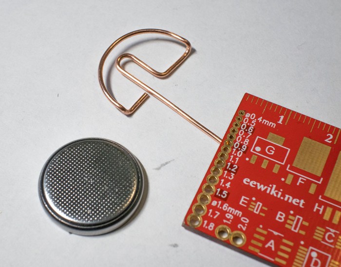
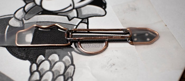
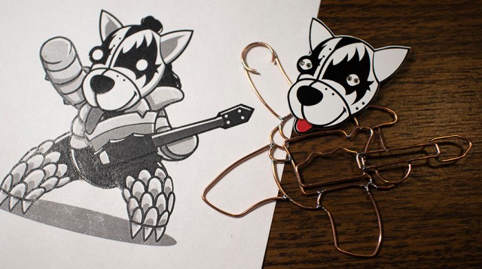
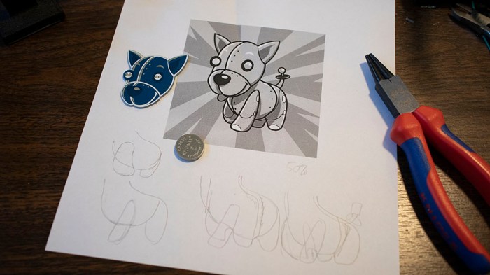
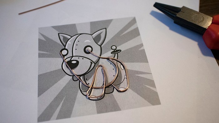
Emily had already soldered a pair of yellow non-blinking LEDs to her Spaceman. For the sake of consistency with the rest of my blinky band, those two LEDs were removed. Then I got to work rebuilding a wire frame body. Given the time crunch, I tried to skim a bit on details and initially started trying to make Spaceman’s guitar out of a single length of wire.

Spaceman 2 one piece guitar

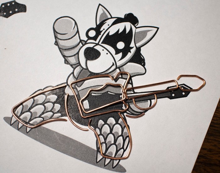
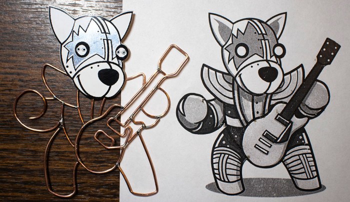
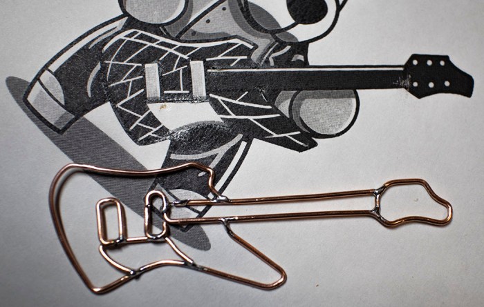
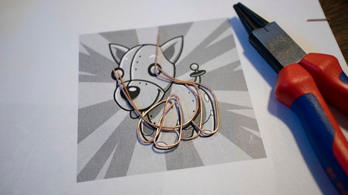
I only got this far, though, before I decided it didn’t look good. I aborted and returned to multi-piece construction. It is more time consuming, but it conveys superior detail.

Spaceman 2 multi piece guitar.jpg

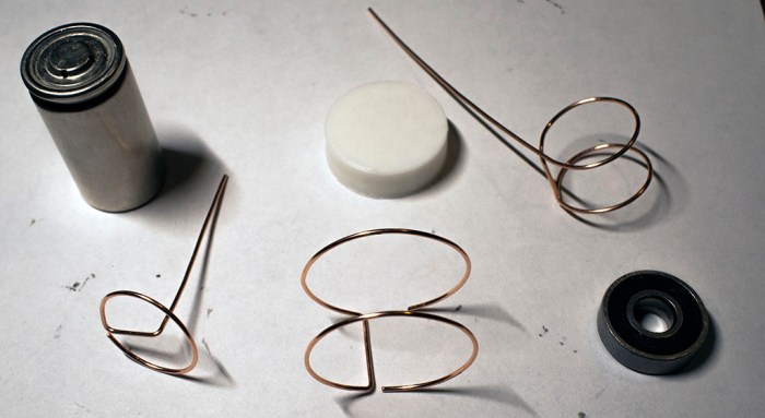
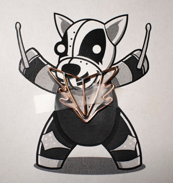
Unfortunately that aborted experiment put me further behind on schedule. This is not the time to experiment, I need to stick with known solutions. For the most part, I stuck with what I knew worked for the rest of this reconstruction.

Spaceman 2 complete

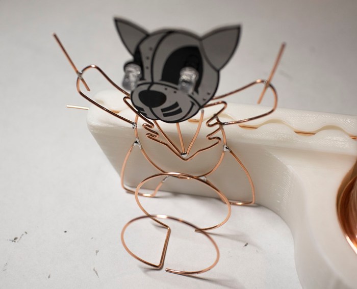
I’m sad that I lost my first KISS Tindie Spaceman, but this experience also gave me the opportunity to answer one question I was asked: How long does it take to build a wire frame body for a KISS Tindie? I honestly did not know because when I’m focused on a project like this I lose track of time. Bend wire, compare against drawing, repeat until the curve is right. Then solder that piece, and repeat the whole process for the next piece.

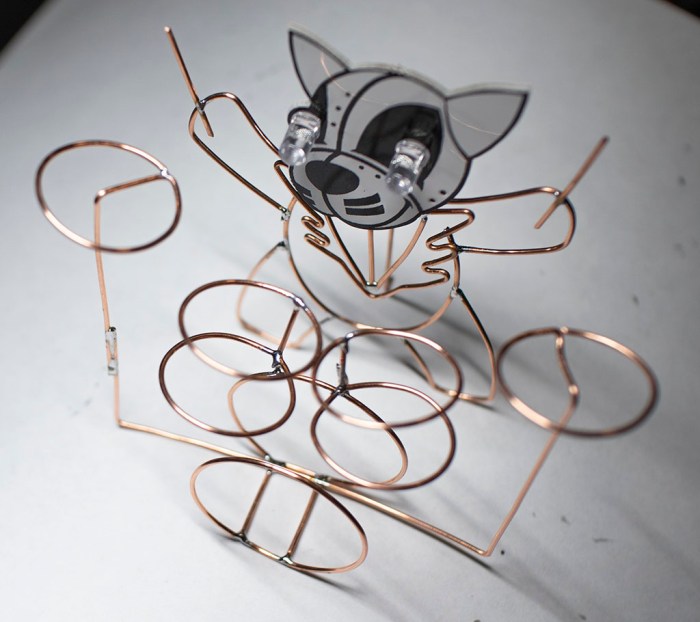
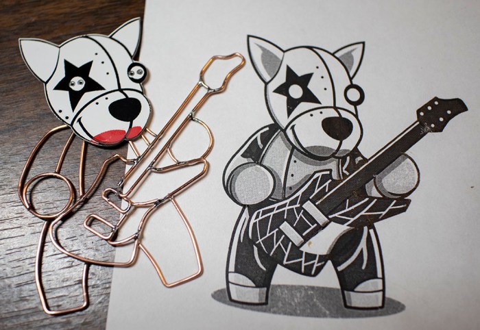
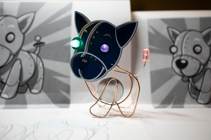
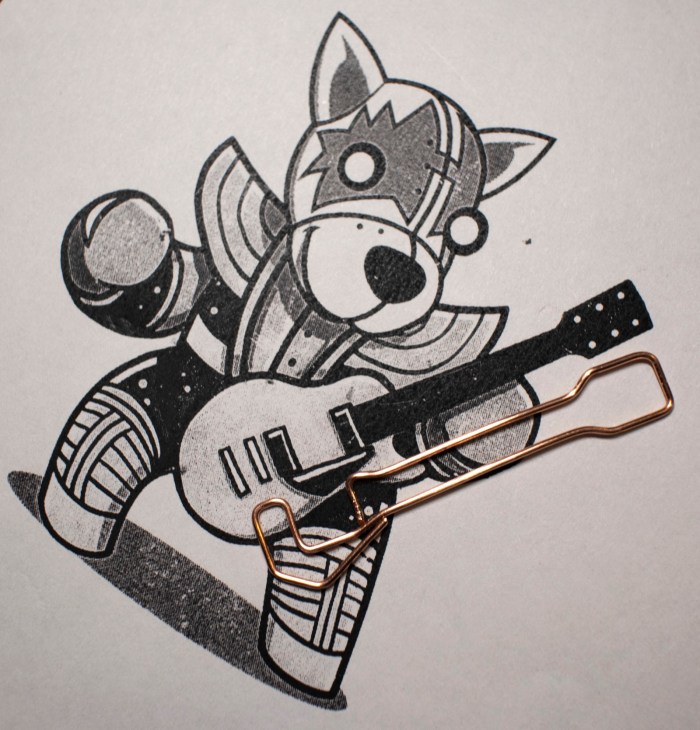
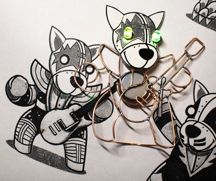
I had guessed maybe each Tindie would take 30-45 minutes. This time, I started a timer just before I removed the yellow LEDs and stopped it right after I took the above picture of a completed KISS Spaceman II. Total time: 2 hours 45 minutes. Even though this included the aborted single-wire guitar, my estimate was clearly way off!

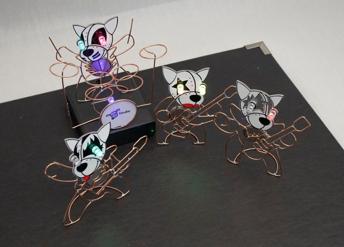
But that time was well spent, I had the full band again for my Sparklecon presentation.

KISS Tindies will be at SparkleCon

SparckleCon IV, the annual event held by 23b Shop, will be this upcoming weekend. It will be my first opportunity to attend and it looks like I’ll be jumping in with both feet and presenting part of a talk. Currently scheduled for Sunday morning at 9AM, the topic is Hackaday and Tindie, with focus on the recently concluded circuit sculpture project.

Ironically, there won’t be any actual contest entries at the presentation, because staff members like myself were not eligible to enter. So I’m bringing the next best thing: my KISS Tindies band which I built because I thought circuit sculptures looked like fun.

kiss tindie band on stage

The talk will be a condensed summary of my circuit sculpturing adventures documented on this blog. From my initial Tindie puppy, to my wire straightening tool, to the four members of the band and finally the drum set. The topic will neatly tie into both Hackaday and Tindie and it’s my way of making sure I hit the standard points without being too much of a corporate commercial.

We’ll see how successful the venture will be… my brain isn’t typically working at its best Sunday mornings at 9AM, and some fraction of the conference attendees will be hungover in bed. I choose to see this as a positive thing: it’s good practice for my public speaking skills, and any goofs would likely go unnoticed (or at least forgiven) by an equally night-owl-heavy crowd.

KISS Tindies: On Stage

Now it’s time to wrap up the KISS Tindies wireform practice project with a few images for prosperity. Here’s the band together on stage:

kiss tindie band on stage

An earlier version of this picture had Catman’s drum set in its bare copper wire form. It worked fine, but I recalled most drum sets I saw on stage performances had a band logo or something on their bass drum surface facing the audience. I hastily soldered another self blinking LED to my drum set, arranged so it can draw power from a coin cell battery sitting in the drum. Calling this a “battery holder” would be generous, it’s a far simpler hack than that.

kiss tindie drum set blinky led

I then printed a Tindie logo, scaled to fit on my little drum. Nothing fancy, just a standard laser printer on normal office printer. I then traced out the drum diameter and cut out a little circle with a knife. Old-fashioned white glue worked well enough to attach it to the copper wire, and that was enough to make the drum set far more interesting than just bare wire.

A black cardboard box lid served as a stage, with a 4xAA battery tray serving as an elevated platform for the drummer. I watched a few YouTube videos to see roughly where Demon, Spaceman, and Starchild stand relative to each other and Catman as drummer. It may not be a representative sample, but hopefully it eliminated the risk of: “They never stand that way.”

With batteries installed in everyone, it’s time for lights, camera, action! It was just a simple short video shot on my cell phone camera, one continuous pull back motion as smooth as I can execute with my bare hands helped by the phone’s built in stabilization. I had one of the aforementioned YouTube videos running for background sound.

I wanted to start the video focused on the drum logo, but doing so requires the phone right where I wanted Demon to stand. After a few unsatisfactory tests, I decided to just add Demon mid-scene after the phone has moved out of the way. It solves my position problem and adds a nice bit of dynamism to the shot.

KISS Tindie: Battery Power

When I started the KISS Tindie heads project, the primary goal was and remains an exercise in forming shapes with copper wire. Making these copper wire bodies purely for cosmetic decoration with no functional circuit. With that goal met, I’ve changed my mind about nonfunctioning circuitry. I should at least give it a shot.

It was trivial to solder self-blinking LEDs into their designated slots on each PCB. The next challenge was to provide power to those LEDs. The original battery holder slot is no longer available – I’ve already used those contact pads to connect my copper wire bodies to these PCB heads. On the upside, it meant the wire bodies were ready to serve as ground plane.

The other major solder point was intended for a pin that lets us pin the Tindie Blinky on our clothing. I had soldered the positive leg of a LED to that pad and a long straight wire as a tripod to help the KISS Tindie stand up. I thought perhaps I could lay down some copper foil tape and my figures can draw power from that tape.

Once I had the wire soldered, though, I didn’t like how it made my KISS Tindies look like they have a mind control cable sticking out the back of their heads. (See left side of picture at the bottom of this post.) Which meant another change of plans: give them each a coin cell battery holder made out of bent copper wire.

wire bent coin cell battery tray for tindie

That loop of wire hugs the positive side of a coin cell battery, pushing the negative side against a KISS Tindie’s copper wireframe body. This completes the circuit and the coin cell battery is the visible heart of each KISS Tindie.

kiss tindie with battery heart

And now, in order to stand, a short loop is soldered to the feet. This completes a self-sufficient KISS Tindie figure that stands on its own, as seen in the right side of the picture below. I find this much better than a wire sticking out the back of Tindie’s head, seen on the left.

kiss tindie stand before and after

(Cross-posted to Hackaday.io)

KISS Tindie: Drum Set

The four KISS Tindie PCB heads now have copper wire bodies, but only three of them have their instruments. They can’t go on tour like this – the drummer needs a drum set!

Kidding aside, a copper wire frame drum set would be a good first step into creating three-dimensional shapes using copper wire. I had thought about creating the band members’ bodies in three dimensions, but such complex shapes were above my current skill level — making it in two dimensions was challenging enough.

But perhaps the simpler cylindrical geometry of a drum set would be within my reach. Or at least, a simple caricature of a drum set, since everything I know came from 15 minutes of reading Wikipedia. The biggest drum that dominates visually is called the bass drum, so I started crafting cylinders to get a feel of size. I settled on this size which was shaped using a 3D-printed 30mm diameter cylinder.

tindie drummer bass drum

Once I picked a size for the bass drum size, I started trying every round thing on my workbench to see how well their diameter might work for the other drums. The outside diameter of a 608 bearing seemed a little too large, but the diameter of a sub-C nicad battery cell is just about right.

tindie drummer other drum components

Some wire bending and soldering later, we have a vague approximation of a drum kit as built by someone with no knowledge of drums. But it gets the point across – our KISS Tindie drummer the Catman now has a drum set.

tindie drummer with drum set

(Cross-posted to Hackaday.io)

KISS Tindies: Peter/Catman Completes The Band

Fourth and final member of KISS Tindie heads project represents the Catman. Unlike Starchild, Spaceman, or Demon, Catman is the drummer and has no guitar. This makes the figure itself easier as there’s no axe to form. The only item of any complexity were his lapels, which required sharp bends that I couldn’t quite make in copper wire. But it’s all a simplified approximation anyway so…. hopefully good enough.

KISS Tindie Peter Catman start

Soldering it together was a little tricky, but after I started using tape on Spaceman, my proficiency is now good enough for me to handle it as a problem I know how to solve.

KISS Tindie Peter Catman progress

With the chest details in place, the rest of the drummer were pretty simple.

KISS Tindie Peter Catman complete

In fact, too simple. I’m not happy with leaving the drummer standing up holding a pair of drumsticks… but more on that later. For now, I have taken the four KISS Tindie heads and, using existing reference artwork, given them simplified copper wire bodies. Here they are overlaid on top of my reference sheet.

KISS Tindie band with reference

And here they are without the reference art:

KISS Tindie band no reference

This was a fun project to trace out existing artwork using copper wire. But I’m not done yet. For starters, Catman the drummer needs a drum set.

(Cross-posted to Hackaday.io)

KISS Tindies: Gene/Demon

I know nothing about the band KISS or their music, but I have a PCB of Tindie puppy heads styled after stage makeup for the band. I wanted something to practice forming shapes with copper wire, and these looked fun. After tackling Starchild and Spaceman, next up is Demon. (All names I pulled out of Wikipedia.)

The previous two were done piecemeal: I formed one piece of wire, soldered it, then formed the next piece, then soldered that. With Demon I tried to form all the wires first before I start soldering, but tracking my pieces became difficult only about halfway through. I had to move wires around to keep them out of the way of the curve I’m actively tracing, and pieces intended for soldering (shown in this picture) were getting lost among extraneous pieces that were cut off. (Not in this picture, but certainly all over my work area!)

KISS Tindie Gene Demon pieces

Another experiment was to add some dimensional layering to the project. I retreated from building a full three dimensional body to a two-dimensional project, but I could still layer objects at varying heights to add a tiny bit of third dimension action. Seen here is the left hand (front-left paw?) behind/under the guitar.

KISS Tindie Gene Demon layers

As it turned out, soldering multiple pieces at once wasn’t noticeably faster than doing it one piece at a time. And there was a negative downside: since I’m not referencing the overall shape as I go, small errors in each individual piece added up as I didn’t have a chance to correct errors as I went. Demon ended up a little larger than the reference art, with a more distorted shape relative to the rest. But at least his axe looks good.

KISS Tindie Gene Demon axe

For the rest of Demon, I went back to soldering each piece as I bent them.

KISS Tindie Gene Demon complete

(Cross-posted to Hackaday.io)

KISS Tindies: Ace/Spaceman

Continuing the project to give KISS Tindies copper wire bodies, I moved on to the next PCB puppy head. Wikipedia tells me this one is the Spaceman. Just like I did with Starchild, I started with the guitar and built outwards from there. Bending wire is still slow going. I’m sure skilled artists and sculptors could have done it in a fraction of the time, but I won’t get better unless I practice!

I’m also trying out different techniques as I go. I struggled to hold Starchild parts together as I soldered, so for Spaceman I tried out a technique I saw in the Hackaday Supercon SMD soldering challenge: use tape to hold things in place. The picture showed high temperature Kapton tape, I just used plain desktop Scotch tape. This meant another learning opportunity: I’ve learned copper wire conducts soldering heat very well. It doesn’t take much to degrade the adhesive on Scotch tape, leaving residue on my copper wires. Thankfully the plastic substrate could stand quite a bit before it would melt as well, so the shape holds up through soldering.

KISS Tindie Ace Spaceman tape

Another novelty of Spaceman was the open loop forming his right hand. (Front-right paw?) I’m a little worried it would hook on things in the future, but I have to admit that it seems to work well visually.

KISS Tindie Ace Spaceman complete

(Cross-posted to Hackaday.io)

KISS Tindies: Paul/Starchild

With art reference in hand, printed to match scale with my KISS Tindie PCB heads, it’s time to start bending wire for my KISS Tindies project! I started with the face in the upper-left corner of the PCB, which Wikipedia told me represented “The Starchild” by Paul Stanley. The first wire I bent was for his right arm, but as I looked at my reference drawing I realized the critical part of this whole project would come down to whether I can make the guitar work in copper wire.

So I started on the guitar next. Bending wire to mimic features on my reference art. There were a lot of details on this guitar and, after thinking over how much time I wanted to spend on this project, I decided to skip out on those fine details. My copper wire curves will represent just the major character lines.

KISS Tindie Paul start

So the next question for project go/no-go is whether a simplified version of the art would look good enough to proceed. The guitar curves were painstakingly retracing in copper wire, and I decided the results were good enough to continue.

KISS Tindie Paul guitar

Here’s my simplified version of Paul’s Starchild rendered in copper wire. I think the important parts have been sufficiently represented, and I can always come back later to solder in more details if I wanted. This is encouraging enough of a result for me to proceed with the rest of the band.

KISS Tindie Paul complete

(Cross-posted to Hackaday.io)

KISS Tindies: A Wire Form Practice Project

After I built a very simple copper wire body for a Tindie blinky, I wanted to advance my copper wire forming technique with practice making something a little more complex. Looking on my workbench of stuff, the most obvious candidate for a follow-up project are the KISS Tindies given out at Hackaday Superconference 2018. They were the demonstration objects in a workshop on pad printing – people were invited to apply red to these circuit boards and take them home. Not everyone took theirs home, so extras were distributed to other interested Supercon attendees like myself.

KISS Tindies

So I could create some copper wire bodies for the band. It wouldn’t make sense to give the same dog bodies to these heads – these call for some stylized human-like poses. I thought I would have to dig deep into my meager artistic skills to draw a guitar-playing puppy, but it turns out art already existed for these heads. (It’s possible these PCB heads were actually made from the art – I don’t have the history here.)

KISS Tindies reference art

Unlike the puppy, though, there wasn’t an obvious way for me to separate these shapes into a “front” and “back” for the two voltage planes. I thought I might try to make fully three-dimensional bodies but a few tests indicate I don’t yet have enough skills as a copper wire sculptor to pull it off.

Scaling my ambitions back down to match my current skill level means the next project will take a slight step backwards in functionality: they will be flat figures, and the body won’t be a functioning circuit. The focus of this exercise is to practice wire forming on a flat plane.

(Cross-posted to Hackaday.io)

A Copper Wire Body For Tindie

With the wire spool ready to go, it’s time to tackle a simple starter learning project. For the subject I turned to the simple Tindie blinky badge. The badge itself is a soldering exercise, and now it will also serve as a freeform circuit exercise: I will give the Tindie puppy a copper wire body!

Tindie copper body 4 with tail

There will be two loops of wire, one will be electrically connected to battery positive, other loop will be connected to battery negative. There are two existing positions for LEDs on the badge, and I will be adding a third LED to give Tindie puppy a flashy tail. Each LED will bridge the two loops of wire for power.

The Tindie logo was printed up, scaled so printed head matches circuit board size. Then I start tracing out curves as nominees for positive and negative loops.

Tindie copper body 1 planning

Once I had a plan, three segments of wire formed the positive loop, which has Tindie’s two left legs and most of the body.

Tindie copper body 2 front

The negative loop has Tindie’s two right legs and some duplication of body curvature. I had to make sure it reached back far enough for the tail LED to get power. The two loops also formed a battery holder between them. It was important for the battery to be in the body if I wanted Tindie to sit on paws, because if I used the default battery holder in the head our puppy would topple over from being too top-heavy. And the natural place to put a battery in the body is in the chest, as heart of the machine.

Tindie copper body 3 front and back

Some soldering work later, Tindie is standing on paws of a shiny copper wire body, complete with blinky tail. Since the two loops of wire are only held together by leads of the three blinking LEDs, it is rather fragile. For future projects I need to find additional ways to brace positive and negative loops without short circuiting them. Either more electronic components or non-conductive structure.

(Cross-posted to Hackaday.io)