Maintain Relative Spacing Between M3 Nuts in Misumi HFS3 Aluminum Extrusions

In the previous post I described how to keep individual M3 nuts in place on a Misumi HFS3 Aluminum Extrusion. After I started using those little 3D-printed holders to keep the nuts in place, I ran into a related but different problem.

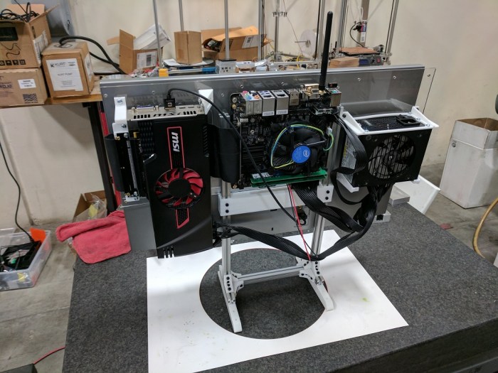
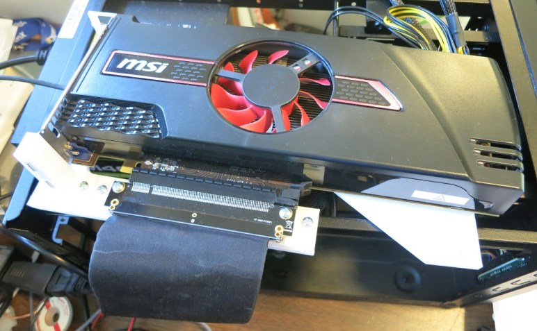
Some large parts require more than one fastener to hold them to the extrusion. And some of these parts get moved around as I revise the details of my design. A specific large bracket required four nuts and, after pushing the M3 nuts around (all four every time I moved the bracket) I started thinking about how to improve this process.

The first answer was to scale my existing design upwards. Instead of a tiny object that holds a single M3 nut, create a longer strip that holds multiple nuts in place. In practice, the friction of a longer strip causes many problems. When pushed, the strip will want to bend instead of move, which increases the pressure on the sides of the rail, which made it even more resistant to moving. And when pulled, the strip is not strong enough to stand up to the strain and would break apart.

The second answer is to reduce the size so there’s less frictional stress to bend or stretch and generally break the strip. But then the old problem came back: with less friction, the nuts would move around if the frame is jostled or tilted. It’s nice that they all move together, maintain proper spacing, but that’s not terribly useful.

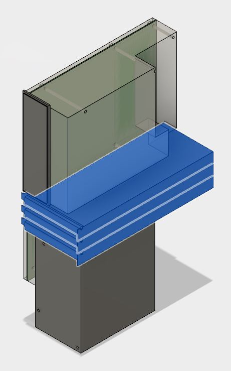
The third answer is to combine elements from the previous two: the strip inside the rail is still loose and free to move, but I added a tab that sticks above the rail. This tab is large enough to provide friction against the rail edge. As the friction is at tab, friction would not cause the rest of the strip to bend or stretch. Since such a strip is customized for a particular part, the tab is also specialized to the mating part. When the tab is pushed up against the side of the mating part, all the nuts on the strip are at the appropriate places.

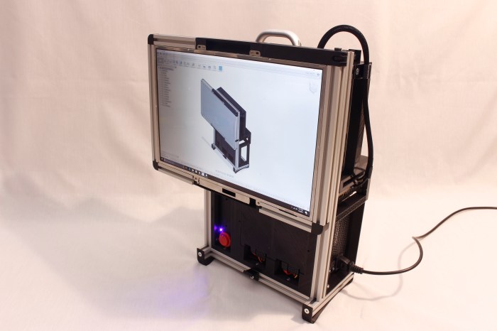
With the help of this strip, it is now much easier to move the brackets around to try out different ideas.

Nut locator strip


Make M3 Nuts Stay Put in Misumi HFS3 Aluminum Extrusions.

While putting together the exterior extrusion frame for Luggable PC Mark II Revision B, I got frustrated with another recurring headache. Aluminum extrusions (like the 15mm Misumi HFS3 I’m using) are shaped so I could put fasteners (in this case, standard M3 nuts) in a rail to fasten things at arbitrary locations along the extrusion. The fact the nuts can slide anywhere along the rail also meant they don’t stay still. If I place the nuts at the desired locations, I have to be careful not to bump or tilt the assembly or the nuts will go sliding out of position.

After too many episodes of nuts moving out of place, I decided to put some thought into the problem. I ended up with a small 3D printed part I can insert into the extrusion along with the M3 nut. It is large enough to rub against the edge of the rail and thereby holding the M3 nut in place, but small enough that it can still be moved with a little push.

Nut hold insert

It was a challenge to dial in the exact dimensions. The acceptable range is very narrow – in fact almost too narrow for a consumer-level 3D printer like mine to handle. Within the same batch I printed, some are extremely tight and some are too loose. If I print at a different time of day, some are entirely unusable. I also ran out of one spool of filament during a print, and the new spool (even though it is the same type from the same vendor, probably even the same manufacturing batch) returned different results.

So I have to keep adjusting dimensions and generate different files between batches. Fortunately, since they are small, it is not a huge loss of material to just throw away the unusable pieces. It solves my headache and that’s all I really ask of them.

Extrusion Frame for Luggable PC Mark II Revision B

Revision A of Luggable PC Mark II is a bare-bones skeleton that proved that all the components can more-or-less play nice together. It did not try to do anything beyond that, such as actually being a luggable chassis. That’s the job of future revisions starting with revision B.

Up front and center is to find a way to attach a carrying handle. Rev A had two load-carrying extrusion beams sticking up straight through everything, which was easy to build but got in the way of packaging components around it. For rev. B I wanted to try routing all the structural extrusions around the outside of the enclosure.

When building Luggable PC Mark I I had designed the frame with all the extrusions precisely seated against each other. This turned out to be a mistake because it was very difficult to cut beams to exact lengths and also to have exactly squared-off ends. The edges of the extrusions are dependably precise: the same could not be said of the ends.

Applying that valuable lesson to Mark II meant that all the extrusion-to-extrusion contacts are edge-to-edge. The ends of the extrusions will either go into 3D printed plastic  or just dangle into space. This way, minor error in length and squareness will not affect the overall design.

Misumi does not sell ready-made brackets to bolt 15mm HFS3 extrusions together, so I designed and 3D-printed my own. Since I’m making my own custom designs anyway, it was easy to incorporate features I wanted in my own design. In the case of the exterior frame of rev. B, it meant shock-absorption bumpers for the corners of the frame.

PLA is not very flexible so the impact absorption will be minimal, but it was fun to build.

LugPCM2RB Frame

Installing and Updating Plex Media Server in a FreeBSD Jail (FreeNAS) via ‘pkg’

plex-logo-e1446990678679One problem I had with the FreeNAS plug-in architecture is the lack of a user-friendly update system. (Either it is hard to find, or that it doesn’t exist, it’s not user-friendly either way.) The version of Plex media server I received using the default plug-in installation process was several versions out of date and it looked like I was pretty stuck. In order to update, Google found manual instructions that were… well, let’s just call them ‘nontrivial’.

When I found out Plex media server is also offered as part of the FreeBSD Ports and Packages Collection (tracked via “FreshPorts“) I hoped that might be a much better way to go. I had to manually create the FreeBSD Jail running on my FreeNAS box, which was harder than the built-in plug-in version but was not horrible. Plus, if this goes well, it would be a one-time cost.

After the FreeBSD jail was set up, I opened a shell window into it and typed pkg install plexmediaserver which thankfully took care of downloading and installing all the binaries. The install process also ended with a few paragraphs of instructions on how to configure Plex to automatically start every time that instance of FreeBSD (in my case, the FreeBSD Jail) boots up. Copy-pasting the commands worked as advertised and everything was fairly painless.

I was then able to enjoy my home Plex media server for a few weeks. But there was one unknown: upgrades. I didn’t know how upgrades would work until I needed to perform one, so it’s just a waiting game for a new version of Plex to be released and see how things propagate. This week, the wait was over!

The first notification was from my home Plex media server. Apparently it checks for updates periodically and notifies me when one is available. After waiting a day or two, the update propagated to FreshPorts. Once that occurred, I opened a shell window into the FreeBSD jail running Plex and issued the following commands:

  • service plexmediaserver stop to halt the old running Plex.
  • pkg update to download the latest database of available packages.
  • pkg upgrade to perform updates of any new packages, including Plex.
  • service plexmediaserver start to start the new version of Plex.

I reconnect to the web interface of Plex running on my FreeNAS box, and I see the latest version up and running. Success!

Simplify3D Custom Supports for Lenovo L24q-20 Power Adapter Bracket

The Luggable PC Mark II project is built around the Lenovo L24q-20 QHD (2560×1440) monitor. One of the reasons I chose this screen was because its AC power adapter is relatively small and I thought I could package it within the enclosure. For Revision A, I didn’t do anything fancy: the power adapter is zip-tied to one of the aluminum extrusions. I should do better for Revision B.

Monitor PSU zip tie

The goal is to design a mounting bracket that can hold the AC adapter in place, look relatively elegant, allow easy removal of the adapter, and do it all while taking up minimal space. This is commonly solved by a bracket with flexible claws to hold the object in place, so I designed one of my own tailored to the dimensions of this adapter.

Monitor PSU CAD

My 3D printer can translate this CAD object into the real world, but it needs a little help. Deposition modeling type 3D printers like mine can’t put things in arbitrary locations in space, due to pesky things like gravity. The fastener screw hole in the middle has enough surrounding material for the 3D printer to build up the top of the hole despite gravity, but the tines at the end need to be supported while printing.

This is one of the strengths of Simplify3D as slicer – the ability to customize these printing supports. I wanted supports to help me print the fork tines on the ends, but I didn’t want any support for the fastener hole as they are unnecessary and, if present, would be very difficult to remove. In Cura 2.x (which came with the 3D printer) supports are an all-or-nothing proposition. I could not selectively choose what to support. Simplify3D allows me to do so.

Monitor PSU S3D

And thanks to this custom support, I have a clean fastener hole along with fork tines to hold the power adapter in place. I don’t use Simplify3D custom supports very frequently, but when I do, I’m very glad I have the tool at my disposal.

Less Grumpy About Python 3’s Break From Python 2.

Python LogoI spent more than a decade and a half in a software engineering job where backwards compatibility is a must, all day, every day. It’s very disorienting for me to switch to a world where such a sacred commandment would be discarded as when Python 3 was launched with severe incompatibilities from Python 2.

As a novice to Python, I was not aware of the problems that Python developers tried to leave behind in the break and I’m also ignorant of the positives Python 3 offered as a benefit to balance the cost. All I saw was the aftermath of an incredibly disruptive change that, almost a decade after it started, is still far from complete.

Part of my motivation to learn Python is ROS, which is still on Python 2. This meant I’ll have to deal with the transition costs even though I’m new to the scene. This was not a happy introduction to the world.

Fortunately the lengthy transition also meant there’s been time for people to voice similar concerns and for the people behind Python to write up their explanation. There’s a fairly lengthy explanation on Python.org titled “Should I use Python 2 or Python 3 for my development activity?” which links to an even lengthier “Python 3 Q&A” that has evolved over the past five years.

After reading it all, I see their point. Especially the parts around Unicode support. I can see how changing behavior of a fundamental concept like strings in a language can’t be done without breaking compatibility, and I can understand why it is a required transition for the language to be successful in the rest of the world beyond the English-speaking communities.

I don’t have to be happy about it, but I can at least understand it, and that does help to make me a little less grumpy when I have to deal with the aftermath.

Scratching the Surface of Python Libraries

Python Logo
Python logo from the Python Foundation

It’s somewhat embarrassing to admit my first impressions of Python came from programmer humor. The first one I can recall is xkcd #353. Another one that made an impression was the “If programming languages were essays” series.

The common thread is the tremendous library of tools available to python programmers just a “import” command away. I think the hard part of me getting up to speed in Python won’t be the syntax or the constructs, it’ll be getting to know what libraries are available. I foresee my biggest hurdle to Python productivity would be spending three hours writing something before it occurs to me to look for a library where someone has already done the work, find it, and finish the task in 15 seconds.

It makes sense that this ecosystem of libraries is a huge strength to Python and also an equally huge liability and a hindrance in transition to Python 3. By breaking backwards compatibility, Python 3 had to rebuild this ecosystem of libraries from scratch. It’s hard for people to find motivation to use the new Python 3 – with its limited set of ported libraries – when they could stay with the comfortable group of friends they already know in the Python 2 world.

To learn the ropes, there’s nothing like diving right in. I wanted to write a simple script to handle a task I had: enumerate video files in my collection and call FFmpeg to convert them from their old formats to the modern MPEG 4 Video format (h264 + AAC). Most of what I need to do for walking the directory tree comes from “import os” and “import os.path“. Calling FFmpeg turns out to be trivial after “import subprocess“. And the final icing on the cake: a library to parse command-line parameters using “import argparse“. Argparse even has a HOWTO tutorial to walk me through using it.

In less than an hour, this complete novice was able to build a decently robust Python script for video conversion.  Color me impressed.

tumblr_lltzgnhi5f1qzib3wo1_400

Some Python Points of Interest to a C/C++/C# Programmer

Python Logo
Python logo from the Python Foundation

Zipping through the Python 3 tutorial from the Python Foundation, some things stood out more than others. Coming from a background of work in C, C++, and C#, I found the following items interesting:

Strings

String handling is something every programming language has to deal with and a good way to feel how the language designers solve problems. C approaches bare metal and has historically proven to be error prone. C++ offers the choice of going with C or taking the performance overhead of string libraries in exchange for reduced headaches. C# reflects a more recent school of thinking where the programmer is prevented from shooting themselves and all their customers in their collective feet. Python is in the last bucket and I’m happy to see it.

A different ‘for’ loop

Python’s for loops always iterate over items of a sequence, and not based on an integer index like I’m used to from C and C++. It feels like foreach from C# but hopefully without the negative performance impact.

An ‘else’ block after a loop?

The ‘else’ block of a loop was a novel idea to me. I’ve never had this tool in my toolbox and my brain isn’t used to structuring code to take advantage of this mechanism, but I am optimistic I will find it useful.

Python classes

The Python designers took a very different path to implement classes than any other object-oriented language I’ve learned. The tutorial began with some background, a big wall of text that I originally thought I’d skip thinking it’d be repeating things I already knew. Now I’m glad I put in the effort to read it. Python classes look familiar at first glance, but after reading about the nuts and bolts, I know I’ll get into trouble if I had treated them the same way as C++ classes.

I expect I’ll still get into trouble, but now I’m optimistic I will understand why and be able to dig my way out.

Learning Python 3 (not 2) from Tutorial by Python Foundation

Python Logo
Python logo from the Python Foundation

I took the Codecademy Python class several months ago when I surveyed various technologies. It appears I didn’t write a short note about it which is too bad because I now want to look over what I thought at the time. In my vague memory, they wrote it for the absolute beginner and spend a lot of time teaching basic computer programming concepts. (Variables, flow control, etc.)

Python is again as a topic of interest for me. It is one of the primary languages for working with ROS and also in a lot of machine learning/AI fields. (OpenAI gym is Python, Google’s TensorFlow is primarily focused Python, etc.) I think I should try to gain proficiency in the language but I didn’t want to go through a beginner-focused class again.

To review Python from a different starting point, I started going through the Python Foundation’s own tutorial for Python 3.6. I quickly determined the target audience are people already familiar with programming in another language and want to get up to speed in Python, which perfect for me! It was quite useful for me when the authors described Python features in terms of how it is similar to or different from C++ features.

On the flip side, I was reminded why I was down on Python: the incompatible break between Python 2 and Python 3. They’re both fundamentally the same language but in real world usage they are now effectively two different languages. Python libraries written for Python 2 could not run unmodified on Python 3, and vice versa. So they will have different install instructions, etc. Over eight years after the initial release of Python 3 the entire ecosystem is still undergoing the pain of  this transition.

OpenAI and TensorFlow appears to support both Python 2 and 3, with separate setup and usage instructions. ROS has the official  ambition to move to Python 3 but is currently still stuck on Python 2 due to the existing base of Python libraries.

Despite the temptation to stick with Python 2 for ROS, I decided to jump into the Python 3 tutorial and I’ll deal with Python 2 weirdness as they come up later.

The Tale of the Scale

With the core components and the auxiliary accessories installed, I have a usable computer. It is time to find out how much this setup weighs.

Weighing this configuration establishes a lower bound for the final contraption. Whatever a complete luggable enclosure may weigh, it must have all the parts present on this first draft, so it’d be impossible to be any lighter.

Luggable PC Mark I weighs in at 17.5 pounds and while it is no lightweight, I’ve had no problems lifting it by the handle and carrying it around. Some of the credit goes to the strong and smooth handle sold by Misumi for the HFS-5 extrusion. (HHDFL19) The strength gives confidence for carrying and the smooth surface helps make it comfortable.

Tux Lab’s “Luggable Frame” project with the Yamakasi Catleap 28″ monitor and the HP Z220 small form factor case sets the upper bound for weight. While it can be carried short distances (say, across the room) at over 30 pounds it is not practical to carry much farther. I expect Mark II to be lighter than that combination, but would it be lighter by a useful amount?

I didn’t need precise measurements – it’s just for a rough baseline – so I used the most convenient weight measuring device: my bathroom scale. I mentally gave myself a drum roll as the bathroom scale took measure of the Luggable PC Mark II…

Bathroom scale

And the number that came up was… 16 pounds!

That’s not a bad starting point. I expect the final enclosure to weigh more than 1.5 pounds, so the first usable luggable Mark II will weight more than Mark I. That’s not a huge surprise since the larger screen is significantly heavier than a salvaged laptop panel. The challenge would be to keep the weight as low as it is feasible.

Given a bare-bones skeleton baseline of 16 pounds, I’ve set for myself a target weight for the final product at 20 pounds.

Onward to the next iteration.

Need Low-Voltage, Low Power Wire Bundle? Use Cat 5e Data Cable!

In addition to USB ports, most PC tower cases also come with a front control panel that connects to the motherboard. This is where the power button, the power LED, and the hard drive activity LED are shown to the user. There is sometimes also a reset button, but they appear to be getting phased out. Personally I haven’t needed a reset button in years and any presses of the reset button in that time has been accidental (and usually instantly regretted.)

Part of building my own PC case is supplying these controls myself. This was part of the fun of building Luggable PC Mark I. For the power button, I wired up a big red button of the type typically used for arcade consoles.

The headers are easy to find (*), as are the LEDs and their associated current-limiting resistors. The momentary-on push button is also easily found. What gave me headache were the wires for them all. None of them need to carry a high voltage, or a lot of current, but there is a bunch of them and it was a hassle to keep them the same length and not tangled up. Given the hassle and the lack of need, it is obvious why I didn’t put a reset button on Mark I. Without reset, I only had to deal with 6 wires instead of 8.

Thanks to Tux-lab, I’ve learned a much better idea I can apply to Mark II: use a segment of standard networking cable. In my case, I have a spool of Cat 5e I can cut arbitrary lengths from. Cat 5e has 8 wires, enough for the purpose. Even a reset button if I wanted, which I don’t, so the fourth pair of wires were removed.

This is a neat trick, I’ll have to keep it in mind whenever I need low-power, low-voltage wiring bundles in the future.


(*) Disclosure: As an Amazon Associate I earn from qualifying purchases.

FYI: Lenovo L24q-20 sale $169.99 @ Best Buy

If anybody wants to follow along and build their own Luggable PC Mark II, as of this writing Best Buy has the Lenovo L24q-20 monitor on sale again for $169.99, a $30 discount (~15%) off the regular $199.99 price. I think this is part of the weekly deals so the price should be good through Saturday 8/26, 2017.

UPDATE: Price is back up to $199 as of 8/27, 2017. But since it’s been discounted to $169.99 twice already within the past few months, I’m sure the sale will roll around again.

BestBuyL24q-20Sale

Extra USB Ports Via Motherboard Headers

My Gigabyte Z270N-WiFi motherboard packs a lot of features into a little Mini-ITX form factor. One downside of packing features into the standard motherboard back plate is that they crowd out the USB ports and I’m left with only 4.

Well, 4 of the popular rectangular types anyway. I get a fifth USB port of the new USB-C connector that I like, but don’t have many uses for yet.

The surface of the motherboard was also cramped, and instead of the usual two (or more) USB2 headers, this board had only one USB2 and one USB3 header. Which should be enough.

Typically, a modern PC tower case has a few USB ports exposed to the user, and those ports connect to these headers. Since I’m building my own case, I’ll have to come up with something on my own.

I could buy the pieces and solder up my own, but it’s hardly worth the effort when Amazon marketplace has many vendors selling them ready-made. Since USB2 is not a very demanding specification by today’s standards, I decided I might as well try the lowest bidder first. At the time of my window shopping, that meant this particular two-pack. (*)

These plugs came mounted on metal plates suitable for installation into a standard PC case. The mounting was not a perfect fit: the plug bulged as if the distance between holes on the plate is half a millimeter narrower than the actual distance between screws on the USB plug. But that’s OK in my book, since I’m not using the metal plate anyway. For the Luggable PC Mark II I removed the plugs and zip-tied them to one of the supports. I’ll design a better home for them on the next draft.

The other problem was its wiring sheath not fitting well inside the molded plug. Showing inside wire at the junction. Since I don’t expect much movement and flex in this wire, the lack of strain relief should not be a functional issue.

Bad Strain Relief

The important part is that they function just fine as USB ports.


(*) Disclosure: As an Amazon Associate I earn from qualifying purchases.

Aftermarket Antenna for Gigabyte Z270N-WiFi

One of the reasons I chose to buy my Gigabyte Z270N-WiFi motherboard is right in its name – it has built-in WiFi. Inside the box is a small antenna with two wires. The antenna is on a hinge so it can be tilted at an angle or folded down against the base, which has a magnet on the bottom.

Gigabyte Antenna

I thought this system was well designed for the typical desktop PC. The motherboard ports are usually sitting close to the ground against the wall and not a good place to have antenna stick out. Also, tower cases are typically steel, friendly for magnet attachment. So the bundled antenna and its wires allow the antenna to sit on top of the tower case where it should get a better signal.

My PC, however, is not a typical PC. Steel sheet metal is currently beyond my capabilities, so my case materials will be aluminum extrusion, laser-cut acrylic, and 3D-printed plastic. None of which are magnetic! Also, the placement of the motherboard meant the ports plate is top and center of the case, which is actually an idea location for an antenna.

Thanks to help from Tux-Lab, I learned the WiFi connector on my motherboard plate is of type RP-SMA. Given this information, it was trivial to find all the connectors for sale by Amazon vendors world-wide. I quickly noticed some of them only claimed to support the 2.4GHz band. A quick check on the spec sheet confirmed my motherboard WiFi is a dual-band unit so I need to look for dual-band antenna.

I eventually decided to try this item (*), a simple dual-band design with relatively high gain of 7 dB. After its arrival, I took a few measurements with the iwconfig tool.

  • No antenna: Link Quality=32/70
  • Original bundled antenna: Link Quality = 60/70
  • New aftermarket antenna: Link Quality = 70/70

Fewer wires, simpler design, higher link quality, I think this is a win!

And on a completely silly note, I’m amused by the fact they made my Luggable PC Mark II look like an old-fashioned TV with rabbit-ear antenna.


(*) Disclosure: As an Amazon Associate I earn from qualifying purchases.

Bare Skeleton for Component Fit Test

After all the research and purchasing the parts, it’s time to put them all together to make sure they fit and work together. This first draft is only a test of component fit using a minimalist bare skeleton. It would not yet be a PC that I can lug around.

In addition to the aforementioned GPU mount, I had to design and 3D print a few other parts. The SFX12V PSU needed its own mounting bracket. As did the screen: I had the metal plate mating surface liberated from the monitor stand, but I needed to design and 3D print a part the metal bracket will attach to and in turn attach to the rest of the skeleton.

The skeleton itself is built out of Misumi HFS3 aluminum extrusions, which is 15mm by 15mm in cross section and well-suited to work with M3 screws and nuts. The nuts are the best feature of HFS3 – all I needed were standard M3 nuts. In contrast, HFS5 needed special Misumi M5 nuts that cost way more than standard M3 nuts.

The design of the skeleton is nothing special – a simple functional design that resembles the Yamakasi Catleap + HP Z220 luggable frame built several weeks ago at Tux-Lab.

I needed a laser-cut sheet of acrylic to tie everything together, so I packed up all the bits and pieces in their original enclosures for the trip to Tux-Lab.

Luggable PC Mark II parts

One laser-cut sheet of acrylic and a few hours of assembly work later, I have the first draft for Luggable PC Mark II! The components are left open and vulnerable but that’s not the point of this first draft. It’s just to make sure all the parts fit. Some minor fit issues were encountered but nothing terribly major.

I declare the fitness test a success. Onward to further refinements!

Luggable PC Mark II first draft

Researching PCI Express Extension Cables

Building Luggable PC (Mark I) determined that a direct GPU connection to the motherboard takes up a lot of space. For Mark II, a simple riser card would not fit. That leaves us with using a PCI Express extension cable.

A flexible cable allows significantly more freedom in placement. Given this freedom, I wanted the GPU cooling intake to face the same direction as the CPU fan cooling intake. This is better than a simple riser card, which would result in the two fan intakes facing opposite directions. To flip the GPU (and its intake) around, I’ll need a longer cable to take the circuitous S-turn.

One word of caution: most extension cables are sold to crypto-currency miners (*), who want the flexibility to pack as many GPUs into one computer as possible. Miners are not concerned with bandwidth and latency over the PCIe bus, but I am!

Hunting in the sea of products aimed at miners, my next task is to determine how much I need to pay for a decent quality cable. Amazon vendors sell cables for anywhere from $7 to $70. Some of the reviews left on the $7 cable (*) warned of destroyed components, making me jittery about going cheap. This cable has the potential to destroy a multi-hundred dollar GPU, a multi-hundred dollar CPU+Motherboard, or possibly both! I climbed up the Amazon price ladder until I found a $30 unit by “EZDIY” (*) with a significant number of reviews, none of which complained about destroyed components.

Then it came time to mount everything. The freedom of placement given by the extension cable also takes away the structural connection to the motherboard. I will need to design my own GPU mounting bracket with zero structural help from the motherboard mount.

The PC interface slot standard, built up over decades tracing back to the old ISA expansion cards, is quite a challenge to deal with. Optimized for mass-production with sheet metal, it is not very friendly to hobbyist 3D printing. But it’s a problem solvable with enough creativity in Fusion 360 and multiple test prints on the 3D printer.

Once it was all set up, I tested the configuration of both the extension cable and the 3D-printed custom GPU mount to verify everything works. It was a little jarring to see my GPU sitting on top of the box instead of its usual home inside.


(*) Disclosure: As an Amazon Associate I earn from qualifying purchases.

Researching PCI Express Riser Cards

When I take my Luggable PC (Mark I) around, I sometimes attract attention from like-minded PC builders who look over what I’ve done and offer helpful suggestions. I’m incorporating the Greatest Hits into construction of Mark II. We’ve covered two of them already: (1) Use a Mini-ITX motherboard and (2) use a smaller power supply. Now let’s cover (3) Use a PCI Express riser or extension.

The motivation comes from the fact standard PCI-Express GPU placement is very inconvenient for compact packaging. The motherboard and the GPU are placed at right angles to each other taking up tremendous amount of space. In Mark I I packaged components around the GPU the best I can, but it was far from ideal.

We need more freedom to rearrange these components and that can only come from putting in an intermediary between the PCI Express slot on the motherboard and the GPU connector tab, something that changes the nature of the connection.

First option is a PCI riser card like this unit (*) on Amazon. It gives us a 90-degree turn which is commonly used in servers to fit cards within a rack-mounted enclosure. Rack-mounted servers don’t usually need powerful GPUs, so these customers don’t run into the problem we have: Full power GPUs are two slots wide, the turn means it can only be used at the very edge of the motherboard or else the card will collide with the motherboard. For Mini-ITX boards, this presents an additional challenge because the GPU’s metal bracket, when turned 90 degrees and inserted to the one and only slot on a Mini-ITX board, will also run into the motherboard ports back plate.

Since a simple riser card wouldn’t work for this project, let’s look at extension cables next.


(*) Disclosure: As an Amazon Associate I earn from qualifying purchases.

Researching Small PC Power Supplies

A major goal of Luggable PC (Mark I) was to use components I already had on hand, which meant a full-sized ATX power supply unit (PSU) because I’ve never bought anything else before. For Mark II, I’m opening up the project budget to buy a compact power supply for the system.

There are plenty of small proprietary PC power supplies available in the aftermarket but low-production items will have limited selection and may be difficult to replace. The only units that were remotely interesting were the PSU for high-volume small form factor PCs of large manufacturers like HP or Dell. But they tend to be low powered units rated at 250W or less and also lack the power plugs needed to feed a power-hungry full size GPU.

So I started looking at the standardized PSUs. In the ATX power supply specification I found online (revision 1.31 dated April 2013) I learned there was a significant step in the evolution of ATX power supplies that shifted original focus from the 3.3V and 5V rails over to the 12V rails. This explains the “12V” suffix on some of these specifications – when a manufacturer names their ATX PSU as a “ATX12V” power supply, they declare 12V focus on power capability.

However, the first three letters still describe the physical form factor. I didn’t find many CFX12V or LFX12V units available. TFX12V and FlexATX12V are more common but they are equivalent to those HP/Dell PSUs with low wattage rating and no PCI-Express card power plugs. We want something smaller than ATX12V, so that leaves SFX12V.

Thankfully there seems to be a healthy SFX12V niche in the ecosystem. They do tend to be lower in power rating than full sized ATX12V but I expect 450-600W to be plenty. And they have most of the power plugs of a full ATX12V unit, including those valuable PCI-Express power plugs.

The power plugs actually present a bit of a problem: any wires I don’t use in my system is dead weight and taking up space. In theory this can be resolved with a SFX12V PSU with modular plugs and wires. I ended up getting one modular (Corsair SF450) and one non-modular (FSP Group FSP450) SFX12V PSU to experiment with.

On the physical form factor specification, SFX12V was only a few centimeters smaller in each dimension relative to ATX12V. But those numbers understate the reduction in physical volume. When I pulled them out the box I was quite pleased at how compact they were. This is going to be a tremendous help in keeping Mark II slim.

IMG_5201
ATX12V and SFX12V power supply units side by side illustrating difference in volume.

Lenovo L24q-20 Monitor: Core of Luggable PC Mark II

Once I decided the Luggable PC Mark II project will be built around a retail available 24″ monitor with QHD (2560×1440) resolution, it narrowed down the list of screens I need to keep an eye open for deals. A few weeks after the decision, a promising candidate popped up: Best Buy put the Lenovo L24q-20 on sale for $170, a 15% discount from its usual $200 price.

The specifications look promising. The panel type is IPS, which is great as I had expected to find only the TN panels in the lower price range. The physical dimensions are impressively minimal, with a very thin bezel on the top and sides. More than half of the back side is flat, making it easy to pack computer components in that space. The shipping weight is light, implying either the screen is lightweight (good) or that they really skimped on packaging (not as good).

The monitor had few inputs (one HDMI port and one DisplayPort) but I only need one so that’s fine. I was less thrilled with the fact all the plugs (video and power) stick straight out the back instead of pointing downwards. The latter would have made it easier to package everything in a slim enclosure.

The other disappointment is the lack of standard VESA mount points. Their presence would make chassis integration straightforward, but it is not itself a deal-breaker. It depends on whether I can work with the nonstandard mount.

Having done all the research I could over the web, I went into the local Best Buy for a look at the display unit to learn things they don’t put on the spec sheet.

Item #1: Power. I could tell the monitor uses an external power converter, but the specifics were not listed. Ideally the monitor can run on 12V DC because then I could rewire it to draw that 12V from the computer power supply. Sadly this Lenovo takes 19V. On the upside, its DC power converter is very small so I think I can package it in my enclosure.

Item #2: Mount. The final make-or-break factor… how the monitor is mounted to its stand. Again, not something listed on the spec sheet. I turned the Best Buy display unit around, found the release latch, and separated the monitor from the stand. I saw the mating surface of the stand is a metal bracket fastened by 7 Philips screws. I can remove those 7 screws and use the metal bracket in my own chassis as attachment point for the monitor.

Yes, I can work with this! I put the display unit back together and grabbed a box to take home. I bought what turned out to be the last new unit in stock.

IMG_5200
Lenovo L24q-20 monitor stand with the metal mounting bracket removed to show the 7 fastener locations. 4 machine screws into metal, 2 on the left and 2 on the right. In between them, 3 self-tapping screws into plastic. The bottom two round objects are not screw locations – they are posts to help locate the mounting bracket.

New Project: Luggable PC Mark II

I’ve been using my Luggable PC for about four months. It was originally built with retired computer parts, but the concept worked so well I transplanted the guts of my main desktop tower into the enclosure and now it is my only computer. I use it at home connected to my Monoprice 28″ UHD monitor (predecessor to the current Monoprice 28″ UHD monitor) and when I want a computer on the go, I close the screen and take it with me.

1454021491161140759
Luggable PC Mark I

Unfortunately that means leaving the UHD (3840×2160) monitor behind. While the built-in 17″ screen (with the flip swivel hinge I’m proud of) is a respectable 1920×1200 resolution, it feels quite cramped when I’m spoiled by a UHD screen at home.

So that became the motivation for a sequel: the Luggable PC Mark II. The main thrust of the project is a larger, higher resolution screen. And this time, I want to build the chassis around a monitor available at retail, instead of a salvaged laptop panel like the Mark I. Being specific to a salvaged panel is not very friendly for others to build their own. Tailoring Mark II to a monitor people can buy would be better.

So the next question is size. Tux-Lab experiments with the Yamakasi Catleap monitor taught me 28″ is too big to be easily portable. Looking over the computer monitor market for sizes between 17″ and 28″, the 24″ size seems to be the best one to experiment with. It is a popular size with a wide selection of makes and resolutions up to and including UHD if the budget allows for it.

And while external dimensions vary, they are mostly less than 14″ high and 22″ wide. Why these dimensions? They are the limits for carry-on luggage at United Airlines, which seems roughly representative of (or possibly more restrictive than) most airlines. I still hold the dream a Luggable PC can fit in an overhead compartment. (Assuming I can get it past TSA.)

There’s no point in a 24″ FHD (1920×1080) monitor since that’s no better than the screen I already have.  My project budget is not daring enough to jump straight into a 24″ UHD monitor price tag. So the hunt is on for a 24″ QHD (2560×1440) monitor that I should be able to find for well less than half the price.