Pixelblaze LED Helix “Glow Flow” Math

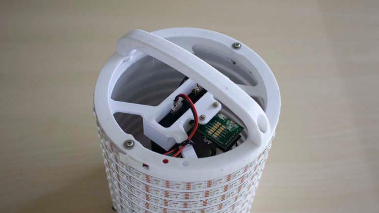
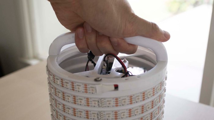
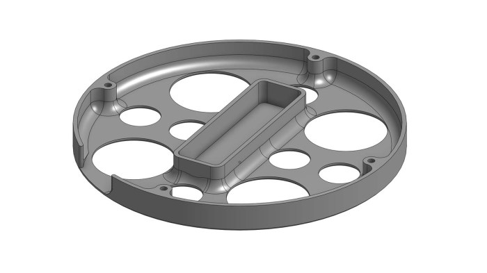
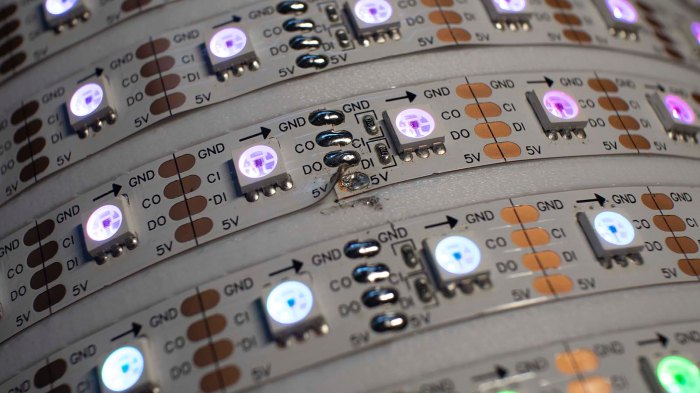
Once new and more ergonomic handles were installed on my LED helix project, it’s time to pause on hardware advancements and switch gears back to software. Let’s see what we can build with what we have on hand before going much further with CAD and 3D printing side of things.

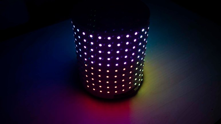
By this point I’ve selected one idea to implement, out of my list of candidate Pixelblaze projects: I want to implement a Pixelblaze pattern that gives the illusion my LED helix is a container holding brightly glowing liquid that moves around inside as it is moved. The accelerometer will provide input for physical motion, and Pixelblaze pattern code will adjust LED colors to present the intended illusion.

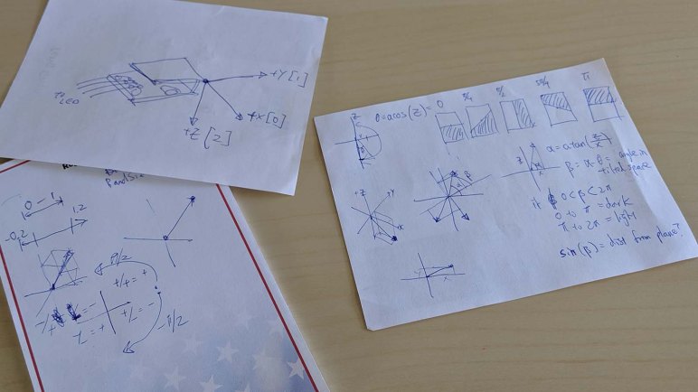
And to accomplish this, we’re going to have to do some math. Liquid sloshes about inside a container in response to sideways movement, and this is the acceleration vector of gravity downwards plus vector of however we’re moving the container around.

Rephrase another way: When a container of liquid is standing still on a flat surface, the downward direction of the container is lined up with downward direction of gravity. But when we start pushing the container around the surface, the downward direction of the container doesn’t change but the downward direction of acceleration does: the direction is now gravity plus motion pushing it across the surface.

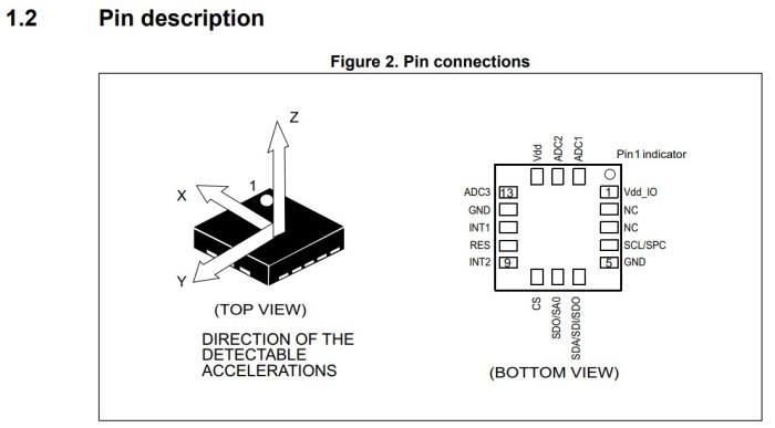
Our LED helix 3D pixel map declares downward direction of the container as its Z axis, and the accelerometer reports downward direction of gravity plus motion. The difference moves the liquid, and this difference can be expressed in spherical coordinates, translated from cartesian accelerometer data with standard formulae. Once the two angles of spherical coordinates have been calculated, they can be used in 3D transforms for each LED’s pixel mapper coordinates.

The result is to translate a LED pixel position based on spherical coordinate of accelerometer tilt, so we can color in a LED depending as a function of the “down” reported by accelerometer. And once the colorfully glowing LEDs start emulating liquid flowing inside a container, we have our project name: the Glow Flow.

Pixelblaze pattern code for this project is available on Github.


New Sturdier Handle For LED Helix Project

The new LED helix top piece gained responsibility for keeping the battery pack in place in addition to aligning the Pixelblaze with LED geometry. The old top piece also provided a few simple handles, but the new top piece has been relieved of that task: there will be a more robust dedicated handle for this LED chassis instead.

The design is mechanically simple: arch attached with one screw at each end. This is a potential downgrade in strength, as the handle is now attached with only two screws rather than four. Hopefully it will still be strong enough.

Replacement glow flow handle v1 too short

The first handle version turned out to be too short. When my hands grasp the handle, my knuckles may bump against some wires or their connectors. It’s something I could avoid if I’m trying to be careful, but I’d like to be able to hand this to other people to play and not have to worry about being careful.

Taller replacement glow flow handle v2

A second, taller handle was printed to provide more clearance. We’ll find out if it does the job. In the meantime… what shall we do with the first handle?

Short v1 handle mounted to the bottom

Rather than tossing it in the trash, I attached it to the bottom end piece. Now the LED helix has handles on both top and bottom end. Now we can hold the helix with both hands and, if held using some compression force pushing the two handles against the middle, there would be minimal stress on fastening screws.

And also, a handle on the bottom meant the assembly no longer sits flat on a tabletop. Forcing the helix to always sit at an angle might be a fun way to show how it responds to gravity. With this round of mechanical upgrades complete, I need to sit down and work through some relevant math necessary for matching software.

Align Axis of Pixelblaze Accelerometer and LED Array

Once I figured out the accelerometer directions for a Pixelblaze Sensor Expansion Board, I realized an earlier oversight was going to cause problems.

Pixelblaze axis misaligned

The first draft of LED helix top end were designed with the following goals:

  1. Have an opening for top end of LED strip to enter interior
  2. Give me something to hold on to.
  3. Physically mount the Pixelblaze somewhere.

Goal #1 was simple to meet. I put in two arched bits of plastic for #2, and there wasn’t a whole lot of thought put into #3. The only goal at the time was to make sure the Pixelblaze doesn’t rattle around and get damaged.

Now that I want to play with the accelerometer and tie it in to my LED strip with 3D Pixel Mapper coordinates in 3D space, I realized my mistake: the Pixelblaze sensor is offset at an angle to the LED. In the image above, the red line represents X axis, the green the Y axis, and yellow is the Pixelblaze at approximately 15 degrees offset from the Y axis. This meant my initial test programs looked odd because the lights were reacting to a force vector 15 degrees offset from where they physically were.

While I could address this strictly in software by changing my 3D pixel map coordinates to match my Pixelblaze axis directions, moving the helix around also exposed more problems with the first draft that I could not solve with just software changes. First, the USB power bank started falling out of place as I had only designed a shallow stand. And second, the thin strips of plastic wasn’t a very good handle for moving the thing around.

So a new top end was designed and printed to satisfy slightly different goals:

  1. Still have the opening for the top end of LED strip.
  2. Give me something to hold on to.
  3. Physically mount the Pixelblaze in a way that aligns accelerometer axis with 3D Pixel Mapper axis.
  4. Hold the USB battery power pack in place.

This top piece no longer has to provide handles, instead I’ll add a dedicated and more ergonomic handle (or two) to this project.

Pixelblaze Sensor Expansion Board Accelerometer Direction

To me, the most interesting peripheral on the Pixelblaze Sensor Expansion Board was its accelerometer module. Its microphone seems to be a decently well-explored space, with multiple examples available on the pattern database, and I haven’t figured out how I would use the light sensor creatively. But there weren’t as many examples of using the accelerometer and I have a few potential ideas there.

The first task of playing with an accelerometer is to determine direction. From Pixelblaze documentation I know it will populate an array accelerometer of three elements for acceleration in X, Y, and Z axis. But which direction do each of these point?

Pixelblaze IDE makes exploration easy. Variables that are export-ed (like the variables to hold sensor values) can be watched live. This simple test program is enough to get started:

export var accelerometer = array(3)

export function render() {
}

Once entered, look for the “Vars Watch” window on the right hand side and a green “Enable” button.

Pixelblaze vars watch accelerometer disabled

Once enabled, Pixelblaze will display values of all exported variables and update them as the pattern is running.

Pixelblaze vars watch accelerometer enabled.jpg

Gravity is a constant acceleration towards the center of the earth, so we could tilt the Pixelblaze around and see which orientation shows the maximum positive number. The downward direction will be aligned with the axis showing the largest number while the other two are nearly zero. Once determined, jot them down in a notebook:

Pixelblaze accelerometer axis handwritten note

To double-check this answer, I went to look up the datasheet for the accelerometer chip itself. Looking on my expansion board, I saw the top was labeled with “*2815 C3H BCSHN” and a web search was inconclusive. Looking into Pixelblaze sensor expansion source code, I found comments marking code to talk with a LIS3DH accelerometer whose data sheet had the following diagram:

LIS3DH pin descriptions from data sheet

All three axis line up as my notes indicated, but their arrows point in opposite direction from mine. Perhaps there’s a convention I’m violating and the arrow actually points opposite of acceleration? This would allow the convenience of a Z pointing up when sitting flat where gravity is accelerating downwards.

Either way, this is enough information to continue. My earlier RGB-XYZ 3D Octants sample program was rewritten to add an accelerometer component. This way the colored blocks move around in response to physical movements of the LED helix. But the visual motion was not intuitive to a human, because my LED pixel mapper matrix does not align with my accelerometer axis. One way to solve that problem is with a new top end piece for my LED helix.

Examining Pixelblaze Sensor Expansion Board

With my RGB-XYZ 3D sweep test program, I’ve verified my LED helix is fully set up with a Pixelblaze controller programmed with its geometry wound around a 3D printed chassis.  I have a blank canvas – what shall I create on it? A Pixelblaze by itself is capable of generating some pretty amazing patterns, but by default it has no sense of the world around it. It can only run a programmed sequence like my sweep test. I could focus on writing patterns for spectacular LED light shows, but I decided to dig deeper for sensor-reactive patterns.

There are a few provisions on board for analog and digital inputs, so patterns could react to buttons or knobs. Going beyond such simple input is the Sensor Expansion Board. It is an optional Pixelblaze add-on board which provides the following:

  • A microphone specifically designed to continue function in loud environments
  • An ambient light level sensor
  • 3-axis accelerometer
  • 5 additional analog inputs

A Pixelblaze fresh out of the package includes a few sound-reactive patterns that work with the microphone. They are fun to play with, but that ground has been covered. Seeking fresh under-explored territory and an opportunity to write something useful for future users, I looked at the other sensors available and was drawn to the accelerometer. With it, I could write patterns that react to direction of gravity relative to the sensor board. This should be interesting.

The sensor board is fully documented on Github, which included description of the protocol used to send data to a Pixelblaze. Or actually any other microcontroller capable of decoding 3.3 volt serial data at 115200 baud which should be all of them! In my case I’ll be using it with my Pixelblaze, and the first lesson here is that we only really need 3 pins out of its 7-pin expansion header: 3.3V power and ground obviously, and since the protocol is unidirectional, only one of two serial transmit pins is used by the sensor board. The remaining pins are pass-through available for other purposes. I’ll explore those possibilities later, for now it’s time to get set up to experiment with the accelerometer.

Pixelblaze Pattern: RGB-XYZ 3D Sweep

The success of a static test pattern in 3D space is encouraging, but it’s still in the realm of something fairly easy to replicate with a simple microcontroller. We have barely tapped into the power of a Pixelblaze controller. Using the pixel mapper is fun, but it’s the animation engine that makes a Pixelblaze exciting.

Resisting an urge to go wild, this next step is only a small incremental step from the static pattern. Again it is a test of all three coordinate axis, and again I will map RGB to XYZ in that order. The difference this time is that each axis and their positive direction will be shown with an animation, and since I’m starting to play in the time domain, each axis will get their own time to shine with an animated band of illuminated pixels.

The band needs to be wide enough to span several pixels, for a smooth handoff between one to the next. If the band covers less than two pixels, it would look more like a collection of blinking LEDs which might be cool but the objective is to convey motion.

Since the coordinate space is passed into render3D(index,x,y,z) in the range of 0 to 1, the naive first approach is to animate from 0 to 1. This turned out to look strange, because the animated band would pop into existance across several LEDs, reach the opposite end, and blink out abruptly. The solution to this problem is to increase the range of sweep so that our band (mathematically) starts off the display space before entering the stage, and exits the stage gracefully out the other end.

But that alone didn’t give us a pleasing sweep. I realized the band is too harsh so an additional blend was required: instead of LEDs turning on and off, there will be a ramp-up and a ramp-down for a smoother edge to the band. This looks better but might get in the way of diagnosing pixel alignment issues, so I left both as option in the code that can be switched back and forth with the style variable.

Code for this pattern is avilable on Github and also shared on public Pixelblaze pattern database as “RGB-XYZ 3D Sweep”

What’s next? Maybe add some interactivity by introducing some sensors into the mix.

Pixelblaze Pattern: RGB-XYZ 3D Octants

Pixelblaze documentation offers a simple pattern for testing that my 3D pixel map volume is indeed doing something in three-dimensional space: a simple call piped coordinates (x,y,z) directly into the HSV (hue, saturation, and value) for a LED color. This turns my LED helix into a cylindrical sample of the HSV color space. With this, I could look for color or brightness variations from one side of the cylinder to the other. A non-repeating variation across a single loop tells me X and Y axis are doing something, and a gradient from top to bottom tells me the Z axis is doing something.

The next step is to go from verifying it does something to verifying the X, Y, and Z axis are indeed pointing in the intended directions. And to do that, I wanted something that visually distinguishes each of the three axis and shows the positive direction for each axis. To meet this requirement, I implemented a Pixelblaze pattern to display my 3D pixel map volume cut up into eight octants.

Each axis will be assigned a color. To keep the axis color assignments easy to remember, They’ll be mapped in the order they’re typically named. Color components are usually listed in RGB order, and coordinates listed in XYZ order. Keeping the same order in both means red is X, green is Y, and blue is Z.

Along each axis, the positive direction half of the pixels will receive the assigned color. Pixelblaze render3D() coordinate parameters are given in the range from 0.0 to 1.0, so pixels with a coordinate from 0.5 to 1.0 will receive the color assigned to that axis.

Examples:

  • (0,0,0) lies in the negative direction of every axis, so it doesn’t receive any color and will be black.
  • (1,1,1) lies in the positive half of every axis, so it receives R, G, and B turning white.
  • (0.75, 0.15, 0.35) lies in the upper half of X, but lower half of Y and Z. So this pixel is assigned red.

This render3D() pattern displayed on a 3D pixel mapped display will visually indicate alignment and direction of X by all the pixels with a red component, alignment and direction of Y with green, and Z with blue.

Code for this test pattern is available on Github, and also shared on the public Pixelblaze pattern database as “RGB-XYZ 3D Octants”.

It is a functional test pattern, but not very visually dynamic. Pixelblaze is all about animated LED patterns, so the next step is to make an animated variant of this test pattern.

Pixelblaze Pixel Map For LED Helix

Completing first draft of a LED helix mechanical chassis means everything is in place to dig into Pixelblaze and start playing with the software end of things. There are a selection of built-in patterns on the default firmware, and they were used to verify all the electrical bits are connected correctly.

But I thought the Pixel Mapper would be the fun part, so I dove in to details on how to enter a map to represent my helical LED strip. There are two options: enter an explicit array of XYZ coordinates, or write a piece of JavaScript that generates the array programmatically. The former is useful for arrangements of LEDs that are irregularly spaced, building a shape in 3D space. But since a helix is a straightforward mathematical concept (part of why I chose it) a short bit of JavaScript should work.

There are two examples of JavaScript generating 3D maps, both represented cubes. There was a program to generate a 2D map representing a ring. My script to generate a helical map started with the “Ring” example with following modifications:

  • Ring example involved a single revolution. My helix has 30 LEDs per revolution around the cylinder, making 10 loops on this 300 LED strip. So I multiplied the pixel angular step by ten.
  • I’ve installed the strip starting from the top of the cylinder and winds downwards, so Z axis is decremented as we go. Hence the Z axis math is reversed from that for the cube examples.

We end with the pixel map script as follows.

function (pixelCount) {
  var map = [];
  for (i = 0; i < pixelCount; i++) {
    c = -i * 10 / pixelCount * Math.PI * 2
    map.push([Math.cos(c), Math.sin(c), 1-(i/pixelCount)])
  }
  return map
}

Tip: remember to hit “Save” before leaving the map editor! Once saved, we could run the basic render3D() pattern from Pixel Mapper documentation.

export function render3D(index, x, y) {
  hsv(x, y, z)
}

And once we see a volume in HSV color space drawn by this basic program, the next step is writing my own test program to verify coordinate axis.

3D Printed End Pieces Complete LED Helix Chassis

My LED helix core has been tested and working, but it needs additional pieces top and bottom for a fully self-contained package. I expect that eventually I’ll pack the interior of my cylinder with batteries, but for now it just needs to hold the USB power bank I’ve been using.

LED helix USB power bank base

The footprint for that power bank defined the center of my bottom piece, surrounded by four mounting screws to fasten this end piece to my just-completed core. A slot was cut in the side for me to tuck in the bottom end of the LED strip. Since this project is still developing, I expect to need to reach inside to fix things from time to time, so I cut a bunch of big holes to allow access, ventilation, and it’ll also print faster than a solid bottom plate.

LED helix top with handle and Pixelblaze mount

My cylinder’s top piece is designed to meet slightly different objectives. It shares the four mounting points, the outer diameter, and a slot for me to tuck in the top end of my LED strip. There were a few extra holes cut in the top, in case I needed an anchor point for zip-ties to hold down wires. I also added two segments curving towards the center to function as rudimentary handles for transporting this assembly. The final feature are two horizontal holes which will house M2.5 standoffs to mechanically mount the Pixelblaze board.

Pixelblaze V3 and M2.5 standoffs

Unfortunately there was a miscalculation and the top piece ran out of filament during printing, ending up shorter than I had planned for it to be. Rather than throw away the failed print, I decided it was close enough for use. I just had to drill my two holes for Pixelblaze mounting standoffs a little higher than planned, and now a few components poked above the enclosure by a few millimeters, but it’s good enough for completing the mechanical portion to support Pixelblaze experimentation.

Next step: configure Pixel Mapper to correspond to this LED helix geometry.

LED Helix Core Assembly

It was a deliberate design choice to build the top and bottom pieces of my LED helix separately, because I wanted to be able to iterate through different end piece designs. The core cylinder hosting most of my LED strip should stay fairly consistent and keeping the same core also meant I wouldn’t have to peel and weaken the adhesive backing for the strip. That said, we need to get this central core set up and running, dangling ends and all, before proceeding further.

LED strip helix soldered joints

Unwinding the LED strip from its spool onto this cylinder, I found one annoyance: this is not actually a single continuous 5 meter strip, but rather 10 segments, 0.5 meters each, soldered together. The solder joints look pretty good and I have no doubts about their functionality, but this seemed to affect LED spacing. The lengths varied just a tiny bit from segment to segment, enough to make it difficult to keep LEDs precisely aligned vertically.

LED strip helix 5V disconnect

Once held on to the cylinder with its adhesive backing, I cut the power supply line halfway through the strip by desoldering one of the 5V joints. (Leaving data, ground, and clock connected.) In the near future I will be powering this project with a USB power bank that has two USB output ports, one rated for 1A and other for 2A. Half of the LED strip will run from the 1A port, and the 2A port will run the remaining half plus the Pixelblaze controller.

Each end of the LED strip was then plugged into my USB power bank, dangling awkwardly, so I could verify all the LEDs appear to be illuminated and operating from a Pixelblaze test pattern.

Next task: design and print top and bottom end pieces. A bottom end piece to manage the dangling wires and hold that USB power bank inside the cylinder, and a top piece to mount the Pixelblaze.

3D Printed Cylinder For LED Helix

Translating the calculated dimensions for my LED helix into Onshape CAD was a relatively straightforward affair. This 5 meter long LED strip comes with an adhesive backing, so a thin-walled cylinder should be sufficient to wrap the strip around outside of cylinder. This cylinder will have a shallow helical channel as a guide to keep the LED strip on track.

That’s all fairly simple, but the top and bottom ends of this cylinder were question marks. I wasn’t sure how I wanted to handle the two ends of my LED strip, since wire routing would depend on the rest of the project. A large hollow cylinder is generic but the ends are task specific. I didn’t want to lock into any particular arrangement just yet.

Another concern is that an >18cm cylinder would be pushing the vertical limits of my 3D printer. Mechanically it should be fine, but it’s getting into the range where some wires would rub against structural members and filament would have to take sharp bends to enter the print head.

To address both of those concerns, I limited the central cylinder to 16cm in height. This would be sufficient to support all but the topmost and bottom most windings in my helix.  This cylinder will have mounting brackets at either end, allowing top and bottom parts of the strip to be handled by separate bolt-on end pieces. They should be much simpler (and faster to print) allowing me to swap them around testing ideas while reusing the center section.

Since this would be a very large print, I first printed a partial barrel in PLA to ensure the diameter and pitch looks correct with the LED strip actually winding around the plastic. PLA is probably not the best idea for this project, though, as bright LEDs can get rather warm and PLA softens under heat. My actual main helical barrel will be printed in PETG.

It was a long print (approximately 26 hours) and a long time to wait to see if it looks any good with my LED strip wound around it. (Spoiler: it looks great.)